
Related Manuals for TEUPEN LEO 21GT


Summary of Contents for TEUPEN LEO 21GT
- Page 1 Serial number: _______________ Translation of the original oper- ating instructions Aerial access platform...
- Page 2 TEUPEN Maschinenbau GmbH Marie-Curie-Straße 13 48599 Gronau, Germany Telephone: +49 (0) 2562 8161-0 Fax: +49 (0) 2562 8161-888 email: info@teupen.com Internet: www.teupen.com Service: Telephone: +49 (0) 2562 8161-313 email: service@teupen.com © TEUPEN Maschinenbau GmbH 2013 Aerial access platform LEO21GT 11.06.2014...
-
Page 3: Table Of Contents
Table of contents Table of contents General..............9 1.1 Information about these instructions..... 9 1.2 Explanation of symbols......... 9 1.3 Limitation of liability........11 1.4 Copyright............. 12 1.5 Warranty provisions........12 1.6 Note regarding warranty card:..... 12 1.7 Customer service........13 Safety.............. - Page 4 Table of contents 3.7 Operating conditions........42 3.8 Hydraulic system......... 42 3.9 Consumables..........43 3.10 Type plate..........43 Structure and function........45 4.1 Overview............. 45 4.1.1 Brief description........46 4.2 Assembly description........47 4.2.1 Platform............ 47 4.2.2 Outriggers..........48 4.2.3 Working basket........48 4.2.4 Crawler chassis........
- Page 5 Table of contents 6.5.1 Overview..........75 6.5.2 Possible assignment of the function keys 75 6.5.3 Examples of the operating modes.... 76 6.5.4 Main menu..........79 6.5.5 Machine data..........80 6.5.6 Service hotline.......... 81 6.5.7 Settings............ 81 6.5.8 Additional information messages regarding machine status......
- Page 6 Table of contents 6.15.1 Switching the machine on/off using the engine controller........146 6.15.2 Platform operation in service mode..148 6.15.3 Outrigger operation in service mode..151 6.15.4 Chain drive in service mode....153 6.16 Valve assignments........155 6.16.1 Valve assignment for platform....155 6.16.2 Valve assignment for outriggers...
- Page 7 Table of contents Combustion engines........217 C.1 Kubota diesel engine......... 219 List of the stickers/symbols...... 11.06.2014 Aerial access platform LEO21GT...
- Page 8 Table of contents Aerial access platform LEO21GT 11.06.2014...
-
Page 9: General
General General 1.1 Information about these instructions These instructions enable the safe and efficient han- dling of the access platform (hereinafter referred to as "machine"). These instructions are a component of the machine and must be kept in the immediate vicinity of the machine so that they are accessible to the per- sonnel at any time. - Page 10 General CAUTION! This combination of symbol and signal word indicates a potentially hazardous situation which, if not avoided, may result in minor or moderate injury. NOTICE! This combination of symbol and signal word indicates a potentially hazardous situation which, if not avoided, may result in property damage.
-
Page 11: Limitation Of Liability
General Additional markings To emphasise instructions, results, lists, references and other elements, the following markings are used in these instructions: Marking Explanation Step-by-step instructions Results of action steps ð References to sections of these instructions and to other relevant documents Listing without fixed sequence [Buttons] Operating elements (e.g. -
Page 12: Copyright
Teupen directly after hand- over of the machine to the customer. If the warranty... -
Page 13: Customer Service
General Please send the warranty card to: Teupen Maschinenbau GmbH Service Point Marie-Curie-Straße 13 D-48599 Gronau Sample of a properly filled-out warranty card: Fig. 1: Sample warranty card 1.7 Customer service Our customer service division is available to provide technical information. See page 2 for contact details. - Page 14 General Aerial access platform LEO21GT 11.06.2014...
-
Page 15: Safety
Safety Safety This section provides an overview of all safety aspects that are essential to the best possible protection of the personnel and the safe and trouble-free operation of the machine. Additional safety instructions for specific work tasks are contained in the sections regarding the indi- vidual life stages of the machine. - Page 16 Safety Work in high places WARNING! Risk of falling! During work in high places, there is a risk of falling. This can cause severe injuries or even death. – Always wear a safety harness (acc. to EN 361) when in the working basket and do not swing or move jerk.
-
Page 17: Hazards Due To Electric Energies
Safety 2.1.2 Hazards due to electric energies Electric current DANGER! Danger to life due to electric current! Upon contact with voltage-conducting parts, there is an immediate danger to life due to electric shock. Damage to the insulation or individual components can present a danger to life. - Page 18 Safety Batteries WARNING! Danger of injury due to incorrect handling of batteries! In case of batteries are improperly handled, there is the danger that the batteries can explode or that liquids that are hazardous to health can egress from the batteries. The liquid egressing can cause severe burns upon skin contact, severe poisoning upon swallowing and blindness in case it comes in...
-
Page 19: Hazards Due To Mechanical Elements
Safety 2.1.3 Hazards due to mechanical elements Falling materials WARNING! Danger of injury due to falling materials! During operation, material can fall down uncontrolled and cause severe injuries. – Make others aware of the danger zone and block off the area. –... -
Page 20: Hazards Due To Hydraulic Energies
Safety Crawler chassis WARNING! Danger of injury due to driving over body parts! With the crawler chassis, there is a danger of pinching off body parts and thus causing severe to fatal injuries. – During operation, do not reach into run- ning chains or chain wheels. -
Page 21: Hazards Due To High Temperatures
Safety 2.1.5 Hazards due to high temperatures Hot surfaces WARNING! Danger of injury due to hot surfaces! Surfaces of engine components can get heated up considerably during operation. Skin contact with hot surfaces causes severe burns to the skin. – Avoid contact with engine components such as exhaust components, silencers, coolers, radiators, pipes and engine blocks. -
Page 22: Hazards Due To Traffic And Vehicles
Safety Engine oil WARNING! Danger of injury through engine oil! Engine oil contains poisonous substances which can cause inflammations and / or are carcinogenic. – Avoid all skin contact with engine oil. – In case of accidental skin contact, wash the hands or affected area immediately with soap. -
Page 23: Proper Use
Safety 2.2 Proper use The aerial access platform is designed and constructed exclusively for the proper use described here. The aerial access platform is to be used exclusively to convey people and tools up to the maximum allowable working basket load (see sticker on working basket) to perform work in high places. -
Page 24: Responsibility Of The Owner
Safety 2.3 Responsibility of the owner Owner The term 'owner' refers to the person who himself oper- ates the system for trade or commercial purposes, or who surrenders the system to a third party for use/appli- cation, and who bears the legal product liability for pro- tecting the user, the personnel or third parties during the operation. -
Page 25: Personnel Requirements
Safety The owner must clearly regulate and specify the responsibilities for installation, operation, fault repair, maintenance and cleaning. The owner must ensure that all employees who handle the machine have read and understood these instructions. In addition, the personnel must be trained by the owner and informed about the risks. - Page 26 Safety In these instructions, the qualifications listed below are named for the personnel for the various areas of activity: Expert An expert is somebody who, based on his professional training and experience, has sufficient knowledge of aerial platforms and is sufficiently familiar with the appli- cable state regulations, accident prevention regulations and generally-recognised rules of technology (e.g.
-
Page 27: Unauthorised Persons
Safety Specialist staff Specialist staff are members of staff who are able to carry out the tasks assigned to them and detect and prevent possible hazards independently as a result of their specialist training, knowledge and experience and their knowledge of the valid regulations. Trained people The trained people have been trained in demonstrable fashion in a training session by the owner about the... -
Page 28: Personal Protective Equipment
Safety 2.5 Personal protective equipment Personal protective equipment serves to protect people against hazards to their safety and health while working. The personnel must wear the personal protective equip- ment while working on and with the machine which is referred specially to in the individual sections of these instructions. -
Page 29: Safety Devices
Safety Safety shoes Safety shoes are used to provide protection from heavy, falling objects and slipping on slippery surfaces. 2.6 Safety devices WARNING! Danger to life from nonfunctional safety devices! If safety devices are not functioning or are disabled, there is a danger of grave injury or death. -
Page 30: Position Of The Safety Devices
Safety 2.6.1 Position of the safety devices View from the left Fig. 2: Position of the safety devices Rotary angle sensor, lower boom (2x) Valves, chassis emergency operation Rotary angle sensor, working basket Tilt sensor Basket scale Rotary angle sensor, pivoting (2x) Outrigger locking mechanism limit Limit switch, lower boom telescoped in switch (1x per outrigger) -
Page 31: Description Of The Installed Safety Devices
Safety View from the right Fig. 3: Position of the safety devices Initiator, basket ladder monitoring Platform valves (optional) Limit switch, upper boom transport Emergency Stop Button on control position panel Circular level Limit switch, upper boom telescoped in Tilt sensor (basket level) Limit switch, retraction rope rope break Battery cut-off switch Limit switch, floor pressure (1x per out-... - Page 32 Safety WARNING! Risk of fatal injury from switching back on in an uncontrolled manner! Switching the machine back on in an uncon- trolled manner can cause serious or even fatal injuries. – Before switching back on again, make sure that the cause for the emergency stop has been cleared and that all safety devices have been installed and are fully functional.
- Page 33 Safety Tilt sensor and circular level (bubble level) During automatic bracing, the aerial access platform is aligned horizontally automatically with the help of the tilt sensor (Fig. 7). Fig. 7: Tilt sensor Fig. 8: Circular level The maximum permissible inclination is 1°; this must be checked visually with the circular level (Fig.
-
Page 34: Symbols On The Machine
Safety 2.7 Symbols on the machine WARNING! Risk of injury due to illegible symbols! Over time, stickers and signs may become soiled or become illegible in other ways. As a result hazards may not be recognised and it may not be possible to follow the necessary operating instructions. -
Page 35: How To Act In Case Of Fire Or Accidents
Safety A list of the stickers and symbols used and their respec- Ä Appendix D tive positions is included in the appendix ( ‘List of the stickers/symbols’ on page 261). 2.8 How to act in case of fire or accidents Preventative measures Always be prepared for fire and accidents! Always keep first aid equipment (first aid kit, blan-... -
Page 36: Environmental Protection
Safety 2.9 Environmental protection ENVIRONMENTAL PROTECTION! Risk to the environment due to incorrect handling of materials which can harm the environment! In case of incorrect handling of materials which can harm the environment, especially improper disposal, there can be significant damage to the environment. - Page 37 Safety Cooling water with frost protec- Cooling water and frost guards contain toxic sub- tion stances. They must not be allowed to escape into the environment. Disposal must be carried out by a spe- cialist disposal company. Rechargeable batteries or bat- Rechargeable batteries and batteries contain toxic teries heavy metals.
- Page 38 Safety Aerial access platform LEO21GT 11.06.2014...
-
Page 39: Technical Data
Technical data Technical data 3.1 Dimensions Data Value Unit Working height (max.) 21.00 m Side reach at 250 kg 12.25 m Overhead reach (max.), point of 9.40 m articulation Working basket height (A) 1.10 m Working basket length (B) 1.40 m Working basket width (C) 0.77 m Overall length (D) -
Page 40: Work Diagram
Technical data 3.2 Work diagram Fig. 12: Work diagram 3.3 Productivity Data Value Unit Basket load (max.) 250 kg Rotating working basket 180 ° Rotation range (max.) 450 ° Chassis height and width 19/46 cm adjustment Gradeability (max.) 19 (34) ° (%) Slope angle 19 (34) °... -
Page 41: Weight And Loads
Technical data 3.4 Weight and loads Data Value Unit Total weight 2980 kg Payload while driving 4.63 kN/m² Payload in working position 1.57 kN/m² (wide bracing) Point load under bracing pad 23.7 kN (max.) 3.5 Drives 3.5.1 Combustion engines Petrol: Vanguard OHV 16 HP Data Value Unit Power... -
Page 42: Emissions
Technical data Cable lengths Data Value Unit Maximum cable length with 40 m cable cross section 3 x 2.5 mm² Maximum cable length with 80 m cable cross section 3 x 4.0 mm² 3.6 Emissions Data Value Unit Noise when driven by electric <... -
Page 43: Consumables
Technical data 3.9 Consumables Consumable Type TEUPEN article number Filling Unit quantity Gear oil Gear oil 3917/0122 * max. 1 l Hydraulic oil Plantohyd 32-S 3917/0066 * approx. Multi-purpose 3917/0095 (cartridge) 0.5 kg grease High-perform- 3917/0130 (bucket) 1 kg ance lubricant... - Page 44 Technical data The type plate is situated on the side of the chassis and contains the following information: Manufacturer Type Serial number Year of manufacture Net weight Load bearing capacity Permitted number of people Additional load Maximum permissible lateral force Maximum permissible wind speed Maximum electrical connected loads Maximum permissible tilt...
-
Page 45: Structure And Function
Structure and function Structure and function 4.1 Overview Overview, left Fig. 14: Overview, left Outrigger 2 Cover, hydraulic aggregate and electric Outrigger 1 motor Control head with control panel and Left crawler chassis socket Control box Working basket Engine controller Control box 11.06.2014 Aerial access platform LEO21GT... -
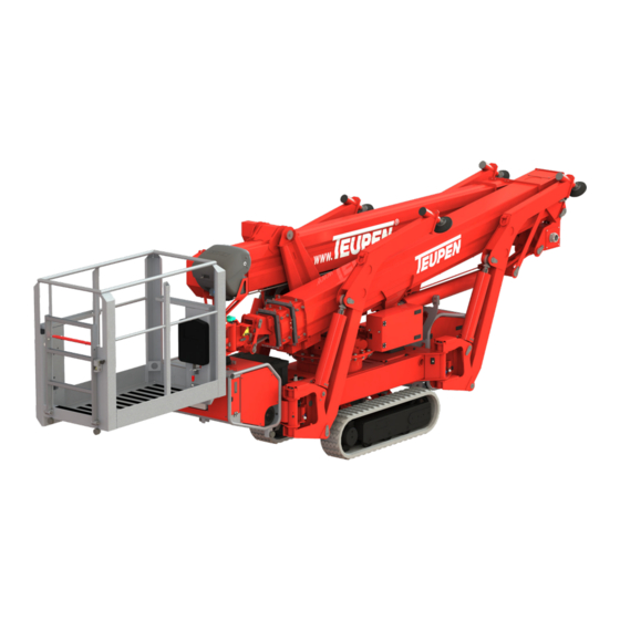
Page 46: Brief Description
Structure and function Overview, right Fig. 15: Overview, right Outrigger 4 Cover, combustion engine Lower boom Right crawler chassis Upper boom Hydraulic control box Outrigger 3 4.1.1 Brief description The aerial access platform is used to perform work at heights. Controlling is performed from the working basket (Fig. -
Page 47: Assembly Description
Structure and function The left-hand (Fig. 14/8) and right-hand (Fig. 15/6) chassis can be adjusted independently of each other either mechanically or hydraulically (optional) and are height-adjustable. The working basket (Fig. 14/4) is kept horizontal at all times by an electro-hydraulic compensation system. Power is supplied either from the mains supply (con- struction side supply point) using an extension cable or by the combustion engine. -
Page 48: Outriggers
Structure and function 4.2.2 Outriggers Fig. 17: Outriggers With the help of the outriggers (Fig. 17/1 to 4), the chassis is lifted and the aerial access platform is thus put into the work position. The outriggers are numbered consecutively according to the position numbers. They can be adjusted independently of one another in two different working positions, narrow or wide. -
Page 49: Crawler Chassis
Structure and function 4.2.4 Crawler chassis In the transport position, the aerial access platform can be moved with the help of the crawler chassis. Only a grease gun is required for the chain tensioning. When adjusting the chassis mechanically, the height and width of the crawler chassis can be adjusted independ- ently in 3 stages. -
Page 50: Operating Elements And Displays
Structure and function 4.3 Operating elements and displays 4.3.1 Outrigger latching The individual outriggers can be latched in the transport position (Fig. 22/4), in the narrow (Fig. 22/3) or the wide (Fig. 22/2) work position using the latching bolt (Fig. 22/1). Fig. - Page 51 Structure and function 2 - Red lamp The red lamp flashes when the basket weight is exceeded. The red lamp also signals faults. 3 - Green lamp The green lamp flashes when the outriggers are not in contact with the ground, are not latched or if the bracing angle is not correct.
-
Page 52: Control Panel In Working Basket
Structure and function 4.3.3 Control panel in working basket Controlling can be performed from the working basket using a control panel. Fig. 24: Control panel in working basket 1 Green lamp 2 Red lamp 3 Graphic display 4 Function keys (4x) 5 Home key (optional) 6 Illuminated start/stop push-button 7 Toggle switch for function selection... - Page 53 Structure and function 2 - Red lamp Indicates malfunctions. Status Description lights up permanently Malfunction blinks Max. basket weight exceeded 3 - Graphic display The graphic display shows the movements available with the respective functions as well as machine data, such as operating hours etc.
-
Page 54: Engine Controller
Structure and function 10 - Toggle switch for rotating Used to rotate the working basket. the working basket 11 - Dummy plug Has no function. 12 - Control levers The control levers can be used to perform the respec- tive colour-coded functions in accordance with the selected operating function. -
Page 55: Display Screen On The Control Box
Structure and function 5 - Arrow key up The arrow key can be used to select the next display or increase values. 6 - Arrow key down The arrow key can be used to select the previous dis- play or reduce values. 7 - Set key The set key is used to confirm inputs. -
Page 56: Connections
Structure and function 4.4 Connections The electric motor is connected by the customer to a 230 V connection (Fig. 28/1). The plug connector is situated underneath the cover (Fig. 28/2). Fig. 28: Power connection 4.5 Work areas and danger zones The work area and danger zones are within and verti- cally below the swivel range of the machine. -
Page 57: Safety Harness (Optional)
Structure and function 4.6.2 Safety harness (optional) Wear the safety harness with fall attenuator when per- forming any work carried out from the working basket. Attach it to the respective fastening points in the working basket. It can be ordered from the manufac- turer. - Page 58 Structure and function Aerial access platform LEO21GT 11.06.2014...
-
Page 59: Transportation And Storage
Transportation and storage Transportation and storage 5.1 Safety instructions for transportation Improper transport WARNING! Danger to life due to improper transport! Improper transport can cause severe injuries or even death. – During transport of the aerial access plat- form, do not stay in the working basket. –... -
Page 60: Transportation
Transportation and storage 5.3 Transportation Attachment points There are several load blocks which are used as the attachment points. They are marked as follows: Attachment points for transportation by crane Fig. 32: Crane attachment point Attachment point for transportation on a trailer Fig. - Page 61 Transportation and storage Attaching Personnel: Trained people Protective equipment: Occupational safety clothing Safety shoes Safety helmet WARNING! Material damage due to improper attach- ment! The use of unsuitable attachment points can cause damage to the machine. – Only use the attachment points specified here.
- Page 62 Transportation and storage Loading Personnel: Trained people Protective equipment: Occupational safety clothing Safety shoes Safety helmet WARNING! Risk of injury due to improper moving of the aerial access platform! With improper moving, the machine can tip or slide. This can cause severe injuries and sig- nificant material damage.
- Page 63 Transportation and storage When the machine begins to topple onto the loading area (Fig. 36/2), reduce travel speed. When the aerial access platform has been set down completely on the loading area (Fig. 36/2) with the chains, the travel speed can be increased again.
-
Page 64: Storage
Transportation and storage On truck with loading plat- form Anchor and secure the aerial access platform to loading platform, e.g. with safety belts attached to the load blocks (Fig. 39/1). The loading blocks are situated on the underside of the machine and are marked with the Fig. - Page 65 Transportation and storage Relative humidity: max. 60 % In case of storage longer than 3 months, check the condition of all parts regularly. If necessary, freshen or replace the rust-proofing. 11.06.2014 Aerial access platform LEO21GT...
- Page 66 Transportation and storage Aerial access platform LEO21GT 11.06.2014...
-
Page 67: Operation
Operation Operation 6.1 Safety instructions for operation Improper operation WARNING! Danger of injury due to improper opera- tion! Improper operation can cause severe injuries and significant property damage. – Execute all operating steps according to the details and instructions in these instructions. -
Page 68: Connecting The Cable Remote Control
Operation 6.2 Connecting the cable remote control Personnel: Trained people Protective equipment: Occupational safety clothing Safety shoes Safety helmet Materials: Cable remote control Open the cover (Fig. 41/1). Fig. 41: Cover Unfasten the bypass plug connector (Fig. 42/1) by turning it anti-clockwise and disconnect it. During operation, the socket (Fig. -
Page 69: Switching The Machine On/Off
Operation 6.3 Switching the machine on/off Personnel: Trained people Protective equipment: Occupational safety clothing Safety shoes Safety helmet Power is supplied either by the mains supply (construc- tion site supply point) using an extension cable or by an independent combustion engine. 6.3.1 Switching the machine on/off at the mains supply DANGER! - Page 70 Operation 6.3.1.1 Switching the machine on/off via the cable remote control WARNING! Risk of injury due to improper operation! Risk of injury for persons in the working basket, when operating the cable remote con- trol. – Only use the cable remote control if there is nobody in the working basket.
- Page 71 Operation Set the toggle switch (Fig. 44/2) on the cable remote control to "1". ð The machine is ready for operation if the green lamp (Fig. 44/1) flashes or lights up constantly. The green lamp flashes when the outriggers are not in contact with the ground, are not latched or if the bracing angle is not correct.
-
Page 72: Switching Machine On/Off Using The Combustion Engine
Operation Connect the plug connector (Fig. 46/1) with an extension cable. In the process, adhere to the Ä ‘Cable lengths’ maximum cable lengths ( on page 42). ð The machine is ready for operation if the green lamp (Fig. 47) on the control panel flashes or lights up constantly. - Page 73 Operation Switch on the cable remote control. To do so, set the toggle switch (Fig. 48) on the cable remote control to "1". Fig. 48: Cable remote control on/off To start up, press and hold the toggle switch (Fig. 49) up for at least 2 seconds. The starting up process on a diesel engine may take longer as it has an automatic temperature-controlled pre-...
-
Page 74: Shutting Down In Case Of Emergency
Operation See also the operating instructions for the combustion Ä Appendix C ‘Combustion engines’ engine ( on page 217). Switching on Check the engine oil level ( Ä Appendix C ‘Com- bustion engines’ on page 217). To start up, press and hold the illuminated push- button (Fig. -
Page 75: Principles Of The Graphic Display
Operation Switch off the machine and secure it to prevent it from being switched back on again. 6.5 Principles of the graphic display 6.5.1 Overview 1–4 Function keys Display screen The graphic display comprises the 4 [function keys] (Fig. 53/1–4) and the display screen (Fig. 53/5). The graphic display starts up when the machine is switched on. -
Page 76: Examples Of The Operating Modes
Operation Symbol Meaning Increase value Confirm input Information message Warning 6.5.3 Examples of the operating modes 6.5.3.1 Chain function In the chain function operating mode the horizontal and vertical tilt of the machine is shown by points (Fig. 54/1) on the coordinate axes. Fig. - Page 77 Operation 6.5.3.3 Platform function In platform function operating mode, the movements currently available to be activated with the operating levers are shown with the lower 8 pictograms (Fig. 56/5). When the limit stop for a platform function is reached, a large pictogram (Fig. 56/3) is shown for the limited movement.
- Page 78 Operation Fig. 59: Working basket transport position As soon as the working basket is in the transport posi- tion, a tick (Fig. 59/right) appears in the display to signal this. Fig. 60: Permitted basket weight exceeded As soon as the permitted basket weight has been exceeded, the display screen indicates this (Fig.
-
Page 79: Main Menu
Operation 6.5.4 Main menu Press the [function key] (Fig. 61/4) in normal mode to call up the ‘Main menu’ . The ‘Main menu’ consists of 4 submenus: ‘Fuel indicator’ ‘Machine data’ ‘Service hotline’ ‘Settings’ (password required) The selected submenu is shown with a grey back- ground. -
Page 80: Machine Data
Operation 6.5.5 Machine data The ‘Machine data’ menu consists of 2 displays and 2 submenus: Display: ‘Operating hours’ Display: ‘Motor hours’ Submenu: ‘Serial number’ Submenu: ‘Versions’ The selected submenu is shown with a grey back- ground. Select a submenu with the [function keys] Fig. -
Page 81: Service Hotline
Operation 6.5.6 Service hotline The ‘Service hotline’ menu displays the telephone number of the respective service company. Use the [function key] (Fig. 66/1) to jump back to the ‘Main menu’ . Fig. 66: Service hotline 6.5.7 Settings Enter password To access the ‘Settings’ menu you need to enter a password. - Page 82 Operation Settings menu The ‘Settings’ menu consists o 4 submenus: ‘Display setup’ ‘Time setup’ ‘Service telephone number 1’ ‘Service telephone number 2’ ‘Language’ The selected submenu is shown with a grey back- ground. Select a submenu with the [function keys] Fig.
- Page 83 Operation Use the [function key] (Fig. 70/3) to set the cursor to "save". ð The assignment of the [function key] (Fig. 70/4) jumps to "OK". Use the [function key] (Fig. 70/4) to confirm the setting. Use the [function key] (Fig. 70/1) to return to the [Setting] menu.
- Page 84 Operation 6.5.7.2 Time setup The ‘Time setup’ menu is used to make the following settings: Time Date Day of the week The selected setting is shown in with a grey back- ground. Use the [function keys] (Fig. 71/2 and 3) to select the desired setting.
- Page 85 Operation 6.5.7.3 Service telephone number Use the [function keys] (Fig. 73/2 and 3) to select the desired digit or special character. Use the [function key] (Fig. 73/4) to confirm the selection. All other inputs are made in the same manner. Fig.
-
Page 86: Additional Information Messages Regarding Machine Status
Operation Additional information messages regarding machine 6.5.8 status The following additional information messages may be shown during operation: Lower control active Lower control active. The control panel is deactivated and the machine can only be operated from the lower controller or using the cable remote control. - Page 87 Operation Soiling display for hydraulic The hydraulic filter is soiled. filter Ä Chapter 7.4.5 Replace hydraulic filter ( ‘Replacing the hydraulic filter’ on page 176). Fig. 79: Inspection of hydraulic filter Engine controller alarm output Fault on the engine controller. Stop operation.
- Page 88 Operation Fault message Various fault messages. They are used primarily to help service staff to detect and clear faults. See also Ä Chapter 8.3 ‘Fault code list’ on page 192. Fig. 82: Fault message Aerial access platform LEO21GT 11.06.2014...
-
Page 89: Moving The Machine
Operation 6.6 Moving the machine Personnel: Trained people Protective equipment: Occupational safety clothing Safety shoes Safety helmet Safety harness WARNING! Risk of injury due to improper moving of the aerial access platform! There is a danger of severe injuries or even death due to improper moving of the aerial access platform. -
Page 90: Moving The Machine Via The Cable Remote Control
Operation 6.6.1 Moving the machine via the cable remote control Ä Chapter 6.2 Connect the cable remote control ( ‘Connecting the cable remote control’ on page 68). Ä Chapter 6.3 ‘Switching Switch on the machine ( the machine on/off’ on page 69). Set the function selection switch (Fig. - Page 91 Operation Use the operating mode selector switch (Fig. 84/2 and Fig. 85) on the cable remote control and the operating mode selector switch (Fig. 84/1) on the control box to select the speed (see the following table "Switch position/speed"). Temperature-dependent travel speeds The fast speed setting (S) is enabled from a hydraulic temperature of +15 °C.
- Page 92 Operation Switch position/speed Cable remote control oper- Control box operating mode ating mode selector switch Travel speed selector switch (Fig. 84/1) (Fig. 84/2) Crawl speed (slow) Fast speed (fast) Fast speed (S) (faster) Hydraulic oil tem- perature higher than + 15 °C By pressing the control levers (Fig.
- Page 93 Operation Table "Move machine" Fig. 87: Movement directions No. Operation Effect Push both control levers towards the The machine moves forwards front Push the left control lever towards the Machine rotates clockwise front and the right control lever towards the rear Push both control levers towards the The machine moves backwards rear...
-
Page 94: Moving The Machine Via The Control Panel
Operation 6.6.2 Moving the machine via the control panel WARNING! Risk of injury due to improper moving of the aerial access platform! There is a danger of severe injuries or even death due to improper moving of the aerial access platform. –... - Page 95 Operation Move the machine with the control levers (Fig. 90/1 Ä ‘Table "Move machine"’ and 2) according to on page 93. If the control levers (Fig. 86/1 and 2) are shifted as far as they will go in fast speed mode, the gearbox also switches to "fast"...
-
Page 96: Setting The Working Position Of The Outriggers
Operation 6.7 Setting the working position of the outriggers Personnel: Trained people Protective equipment: Occupational safety clothing Safety shoes Safety helmet WARNING! Risk of injury due to improper bracing! The machine may topple or slip if it is braced improperly. This can cause severe injuries and significant material damage. - Page 97 Operation The individual outriggers can each be latched in two working positions (narrow and wide). The setting is described in the following using outrigger 3 as an example. WARNING! Risk of crushing! When unfastening the outrigger, there is a risk of crushing if an outrigger is allowed to pivot in an uncontrolled manner.
-
Page 98: Putting Machine In Work Position
Operation 6.8 Putting machine in work position Personnel: Trained people Protective equipment: Occupational safety clothing Safety shoes Safety helmet WARNING! Risk of injury due to improper bracing! The machine may topple or slip if it is braced improperly. This can cause severe injuries and significant material damage. -
Page 99: Bracing The Machine Via The Cable Remote Control
Operation 6.8.1 Bracing the machine via the cable remote control Manual operation WARNING! Risk of injury due to improper operation! Risk of injury for persons in the working basket, when operating the cable remote con- trol. – Only use the cable remote control if there is nobody in the working basket. - Page 100 Operation Use the control levers (Fig. 95/1 to 4) to operate the outriggers 1 to 4 as per the following table. Operation Symbol Effect Push the con- Outrigger 1 is trol lever extended. (Fig. 95/1) for- wards. Push the con- Outrigger 2 is Fig.
- Page 101 Operation Automatic operation WARNING! Risk of injury due to improper operation! Risk of injury for persons in the working basket, when operating the cable remote con- trol. – Only use the cable remote control if there is nobody in the working basket. –...
- Page 102 Operation Set the operating mode selector switch (Fig. 98) to automatic (AUTO). Fig. 98: Operating mode selector switch Use the control levers (Fig. 95/1 to 4) to operate the outriggers 1 to 4 as per the following table. Operation Symbol Effect Push the con- All the outrig-...
-
Page 103: Bracing The Machine Via The Control Panel
Operation Move the chassis into the horizontal position by aligning the outriggers with the circular level (Fig. 100). The bubble (Fig. 100/1) in the circular level must be within the 1° circle (Fig. 100/2). ð If the bracing is correct, the green lamp on the cable remote control lights up constantly. - Page 104 Operation Use the control levers (Fig. 103/1 to 4) to operate the outriggers 1 to 4 as per the following table. Operation Symbol Effect Push the con- Outrigger 1 is trol lever extended. (Fig. 103/1) for- wards. Push the con- Outrigger 2 is trol lever extended.
- Page 105 Operation Set toggle switch (Fig. 105) on control panel to the outrigger function (yellow). Fig. 105: Outrigger function Set toggle switch (Fig. 106) to automatic (AUTO). Fig. 106: Automatic bracing Use the control levers (Fig. 107/1 to 4) to operate the outriggers 1 to 4 as per the following table.
-
Page 106: Operating The Machine
Operation Move the chassis into the horizontal position by aligning the outriggers with the circular level (Fig. 108). The bubble (Fig. 108/1) in the circular level must be within the 1° circle (Fig. 108/2). ð If the bracing is correct, the green lamp on the control panel lights up constantly. -
Page 107: Operating The Machine Via The Cable Remote Control
Operation 6.9.1 Operating the machine via the cable remote control Ä Chapter 6.2 Connect the cable remote control ( ‘Connecting the cable remote control’ on page 68). Ä Chapter 6.3 ‘Switching Switch on the machine ( the machine on/off’ on page 69). Move the machine into work position Ä... -
Page 108: Operating The Machine Via The Control Panel
Operation Operation Symbol Effect Push the control lever (Fig. 110/3) Telescope out the upper boom forwards Pull the control lever (Fig. 110/3) Telescope in the upper boom back Push the control lever (Fig. 110/4) Swivel the platform clockwise forwards (viewed from above) Pull the control lever (Fig. - Page 109 Operation Set the function selection switch (Fig. 112) on the cable remote control to the platform function (blue). Fig. 112: Function selection switch Use the control levers (Fig. 113/1 to 4) and the toggle switch (Fig. 113/5) to operate the platform as per the following table.
- Page 110 Operation Operation Symbol Effect Push the control lever (Fig. 113/3) Telescope out the upper boom forwards Pull the control lever (Fig. 113/3) Telescope in the upper boom back Push the control lever (Fig. 113/4) Swivel the platform clockwise forwards (viewed from above) Pull the control lever (Fig.
-
Page 111: Negotiating Height Differences On Edges
Operation 6.9.3 Negotiating height differences on edges Personnel: Trained people Protective equipment: Occupational safety clothing Safety shoes Safety helmet WARNING! Risk of fatal injury due to incorrect opera- tion! The machine may topple if driven over exces- sively high height differences. This can cause serious or even fatal injuries. - Page 112 Operation Fig. 115: Driving over edges Retract the crawler chassis (Fig. 115/2) completely Ä Chapter 6.11 ‘Crawler chassis height and width adjustment’ on page 125). Move the machine into transport position Ä Chapter 6.10 ‘Moving the machine into trans- port position’ on page 113). Swivel outriggers 1 and 4 (Fig.
-
Page 113: Moving The Machine Into Transport Position
Operation 6.10 Moving the machine into transport position Personnel: Trained people Protective equipment: Occupational safety clothing Safety shoes Safety helmet Safety harness Definition of transport position: Fig. 116: Transport position The upper boom (Fig. 116/1) is on the transport sup- port. -
Page 114: Moving The Machine Into The Transport Position Via The Cable Remote Control
Operation WARNING! Risk of injury when lowering! Due to uneven lowering of the outriggers, the machine can tip or slide. This can cause severe injuries and significant material damage. – Always put the safety harness on when in the working basket. –... - Page 115 Operation Telescope in the upper boom and the lower boom Ä Chapter 6.9 ‘Operating the machine’ on page 106). Swivel the platform in the direction of the transport Ä Chapter 6.9 ‘Operating the machine’ position ( on page 106) so that both arrows (Fig. 117/1) on the rotation indicator are aligned with each other.
- Page 116 Operation Use the control levers (Fig. 120/1 to 4) to operate the outriggers 1 to 4 as per the following table. Operation Symbol Effect Pull the control Outrigger 1 is lever retracted. (Fig. 120/1) back. Pull the control Outrigger 2 is Fig.
- Page 117 Operation Ä Chapter 6.2 Connect the cable remote control ( ‘Connecting the cable remote control’ on page 68). Ä Chapter 6.3 ‘Switching Switch on the machine ( the machine on/off’ on page 69). Telescope in the upper boom and the lower boom Ä...
-
Page 118: Moving The Machine Into The Transport Position Via The Control Panel
Operation 10. Use the control levers (Fig. 124/1 to 4) to operate the outriggers 1 to 4 as per the following table. Operation Symbol Effect Pull the control All outriggers lever are retracted (Fig. 120/1, 2, simultaneously. 3 or 4) back. Fig. - Page 119 Operation Telescope in the upper and the lower boom Ä Chapter 6.9 ‘Operating the machine’ on page 106). Swivel the platform in the direction of the transport Ä Chapter 6.9 ‘Operating the machine’ position ( on page 106). Lower the lower boom completely ( Ä...
- Page 120 Operation Set toggle switch (Fig. 129) on control panel to the outrigger function (yellow). Fig. 129: Outrigger function 10. Set toggle switch (Fig. 130) to manual (hand symbol). Fig. 130: Manual bracing Aerial access platform LEO21GT 11.06.2014...
- Page 121 Operation 11. Use the control levers (Fig. 131/1 to 4) to operate the outriggers 1 to 4 as per the following table. CAUTION! Risk of injury due to improper bracing! When lowering and lifting the outriggers in the transport position, there is a risk of the outriggers colliding with components of the machine (profile package, control cabinets, working basket).
- Page 122 Operation Automatic lowering Ä Chapter 6.3 ‘Switching Switch on the machine ( the machine on/off’ on page 69). Optional "home key" When you press the home key (Fig. 132), the platform automatically moves into the transport position. Steps Fig. 132: Home key 2 to 8 can be omitted in this case.
- Page 123 Operation Continue to swivel the working basket in the direc- tion of the transport position until the transport position is shown on display screen with a tick (Fig. 135/1). Lower the upper boom into the transport position Ä Chapter 6.9 ‘Operating the machine’ on page 106).
- Page 124 Operation 11. Use the control levers (Fig. 138/1 to 4) to operate the outriggers 1 to 4 as per the following table. Operation Symbol Effect Pull the control All outriggers lever are retracted (Fig. 138/1, 2, simultaneously. 3 or 4) back. Fig.
-
Page 125: Crawler Chassis Height And Width Adjustment
Operation 6.11 Crawler chassis height and width adjustment Personnel: Trained people Protective equipment: Occupational safety clothing Safety shoes Safety helmet WARNING! Danger of injury due to improper height/ width adjustment! With improper height/width adjustment, the machine can tip or slide. This can cause severe injuries and significant material damage. - Page 126 Operation Raise the machine using the outriggers so that the crawler chassis is relieved of its load (Fig. 139/h = Ä Chapter 6.8 ‘Putting machine in max. 20 mm) ( work position’ on page 98). Fig. 139: Removing the load from the crawler chassis Remove the hand pump lever (Fig.
- Page 127 Operation Make sure that the locking mechanism has engaged properly in place. To do so, the hand pump lever must have been set back enough so that the two arrows (Fig. 142/1) are positioned one above the other. Fig. 142: Red arrows Retracting the crawler chassis mechanically Ä...
-
Page 128: Hydraulic Height Adjustment (Option)
Operation WARNING! Risk of injury from crushing between crawler chassis and ground! When operating the height adjustment mech- anism, there is a risk of severe injuries from crushing between the crawler chassis and the ground. – Make sure that there are no limbs between the crawler chassis and the floor. - Page 129 Operation Set the function selection switch (Fig. 147) on the cable remote control to the crawler chassis func- tion (red). Fig. 147: Function selection switch Use the control levers (Fig. 148/1 and 2) to operate the crawler chassis as per the following table. WARNING! Risk of injury from crushing between crawler chassis and ground!
- Page 130 Operation Retracting/extending the crawler chassis hydraulically via 6.11.2.2 the control panel Ä Chapter 6.3 ‘Switching Switch on the machine ( the machine on/off’ on page 69). Set the toggle switch (Fig. 149) on control panel to the crawler chassis function. Fig.
- Page 131 Operation Use the control levers (Fig. 150/1 and 2) to operate the crawler chassis as per the following table. Make sure that there are no obstacles (kerb etc.) to the side of the chassis chains as they may stop adjustment of the chassis.
- Page 132 Operation The hydraulic adjustment mechanism is designed for adjusting the height and width of the chassis without having to raise the chassis with the outriggers. If the chassis cannot be adjusted because of unfav- ourable ground conditions, the bracing system will Ä...
-
Page 133: Replacing The Working Basket
Operation 6.12 Replacing the working basket Personnel: Trained people Protective equipment: Occupational safety clothing Safety shoes Safety helmet We recommend that you carry out the work to replace the working basket as a pair with the help of a second person. Removing the working basket Move the machine into the transport position Ä... - Page 134 Operation Turn the basket bolt (Fig. 153/1) 90° anti-clock- wise. Fig. 153: Basket bolt Pull out the basket bolt (Fig. 154/1). Fig. 154: Removing the basket bolt Working as a pair, tilt the working basket (Fig. 155/1) forwards a little and pull it out upwards from the holder (Fig.
- Page 135 Operation Installing the working basket Working as a pair, insert the working basket (Fig. 156/1) into the holder (Fig. 156/2) and push it into the working basket mount. Fig. 156: Inserting the working basket Insert the basket bolt (Fig. 157/1). Fig.
- Page 136 Operation Insert the split pin (Fig. 159/1) into the basket bolt (Fig. 159/2). If the machine has optional "ladder monitoring", connect the plug connection underneath the con- trol panel. Fig. 159: Split pin Tension the working basket. To do so, insert the shackle (Fig.
-
Page 137: Filling The Fuel Tank
Operation 6.13 Filling the fuel tank Personnel: Trained people Protective equipment: Occupational safety clothing Safety shoes WARNING! Risk of fire from improper refuelling! There is a risk of fire from expelled vapours and spilled fuel. – Shut the engine off before refuelling. –... -
Page 138: Emergency Mode
Operation Top up the fuel tank to around X = 2 cm below the tank nozzle. Screw the fuel tank cap (Fig. 161/1) back on. Wipe up any spilled fuel as necessary before starting up the combustion engine. Fig. 162: Fuel filling level 6.14 Emergency mode Personnel:... -
Page 139: Platform Operation In Emergency Mode
Operation 6.14.1 Platform operation in emergency mode Unscrew the cover (Fig. 163/1). Fig. 163: Cover Fig. 164: Platform valves Screw in the pressure relief valve (Fig. 164/Y64) completely. Unscrew and remove the black cap (Fig. 164/Y63) from the release valve and completely screw out the valve actuator. - Page 140 Operation Lock the valve (Fig. 166/Y7) with the locking pin (Fig. 166/1). Fig. 166: Locking pin Open the hydraulic control box (Fig. 167/1). Fig. 167: Hydraulic control box Connect the hand pump lever (Fig. 168/1) to the hand pump (Fig. 168/2). The hand pump lever (Fig.
- Page 141 Operation WARNING! Risk of injury due to improper opera- tion! The machine may topple or slip if plat- form mode is operated improperly. This can cause severe injuries and material damage. – If there are people or objects in the working basket, keep it in a position as close to horizontal as possible.
- Page 142 Operation 11. After emergency operation, remove the locking pin (Fig. 170/1) and move the valve (Fig. 170/Y7) into the centre position. Fig. 170: Locking pin Fig. 171: Valves 12. Completely screw in the release valve (Fig. 171/ Y63). 13. Completely screw out the pressure relief valve (Fig.
-
Page 143: Operate The Outriggers In Emergency Mode
Operation 6.14.2 Operate the outriggers in emergency mode Work as a pair! For outrigger operation in emergency mode, a second trained person is required. Unscrew the cover (Fig. 172/1). Fig. 172: Cover Fig. 173: Valves for outriggers Trained person 1: Completely screw in the pressure relief valve (Fig. - Page 144 Operation Trained person 2: Open the hydraulic control box (Fig. 175/1). Fig. 175: Hydraulic control box Connect the hand pump lever (Fig. 176/1) to the hand pump (Fig. 176/2). The hand pump lever (Fig. 176/1) is situ- ated in the hydraulic control box. Make sure that the hand wheel (Fig.
- Page 145 Operation Fig. 177: Valves for outriggers 10. Trained person 1: Release the valve (Fig. 177/Y7) after emergency mode. 11. Screw the release valve (Fig. 177/Y63) all the way in and completely unscrew and remove the pres- sure relief valve (Fig. 177/Y64). WARNING! Risk of injury due to uncontrolled movements!
-
Page 146: Service Mode
Operation 6.15 Service mode Personnel: Trained people Protective equipment: Occupational safety clothing Safety shoes Safety helmet Definition of service operation Operation of aerial access platform without safety func- tions, using only the hydraulic control without support of the control. Fully hydraulic operation with power supply from electric motor or combustion engine. - Page 147 Operation Starting the combustion engine For the optional diesel engine only: Turn the key (Fig. 178/1) clockwise into the hori- zontal position as shown. ð The engine is preheated. Wait for the pre- heating time to elapse and for the display Fig.
-
Page 148: Platform Operation In Service Mode
Operation 6.15.2 Platform operation in service mode WARNING! Risk of injury due to missing safety devices! In service mode all the safety devices (e.g. limit switches) are disabled. – Perform service mode as per the following instructions. Unscrew the cover (Fig. 181/1). Fig. - Page 149 Operation Lock the valve (Fig. 184/Y7) with the locking pin (Fig. 184/1). Ä Chapter 6.3 ‘Switching Switch on the machine ( the machine on/off’ on page 69). Fig. 184: Locking pin Open the hydraulic control box (Fig. 185/1). Fig. 185: Hydraulic control box Set the key switch (Fig.
- Page 150 Operation 11. After service mode, set the key switch (Fig. 188/1) to the "0" position. Fig. 188: Key switch 12. Remove the locking pin (Fig. 189/1) and move the valve (Fig. 189/Y7) into the centre position. Fig. 189: Locking pin Fig.
-
Page 151: Outrigger Operation In Service Mode
Operation 6.15.3 Outrigger operation in service mode Work as a pair! For outrigger operation in service mode, a second trained person is required. Switch on the machine ( Ä Chapter 6.3 ‘Switching the machine on/off’ on page 69). Unscrew the cover (Fig. 191/1). Fig. - Page 152 Operation Trained person 2: Open the hydraulic control box (Fig. 194/1). Fig. 194: Hydraulic control box Set the key switch (Fig. 195/1) to the "I" position. Trained person 1: Actuate the desired valve by pushing it in as per Ä Chapter 6.16.2 ‘Valve assignment for outriggers’ on page 158.
-
Page 153: Chain Drive In Service Mode
Operation 11. Screw the release valve (Fig. 196/Y63) all the way in and completely unscrew and remove the pres- sure relief valve (Fig. 196/Y64). WARNING! Risk of injury due to uncontrolled movements! If the valves are set incorrectly in normal mode, there is a risk of uncontrolled movements. - Page 154 Operation Set the key switch (Fig. 199/1) to the "I" position. Fig. 199: Key switch Fig. 200: Chain drive Use the valves (Fig. 200/Y22 and Y23) to operate the crawler chassis: Symbol Description Pull Y22 up The left-hand crawler chassis runs in reverse Pull Y22 down The left-hand...
-
Page 155: Valve Assignments
Operation 6.16 Valve assignments 6.16.1 Valve assignment for platform The valves for platform operation are situated in the hydraulics control box (Fig. 202/1) on the right-hand side of the machine. Fig. 202: Platform valves 11.06.2014 Aerial access platform LEO21GT... - Page 156 Operation Fig. 203: Valve assignment for platform Symbol Description Symbol Description Telescope out the lower boom Telescope in the lower boom Telescope out the upper boom Telescope in the upper boom Raise the lower boom Lower the lower boom Raise the upper boom Lower the upper boom Aerial access platform LEO21GT 11.06.2014...
- Page 157 Operation Symbol Description Symbol Description Pivot the platform anti-clockwise Pivot the platform clockwise (viewed from above) (viewed from above) Pivot the working basket anti- Pivot the working basket clock- clockwise (viewed from above) wise (viewed from above) Tilt the working basket to the rear Tilt working basket to the front The basket level release valve (only not required with hand...
-
Page 158: Valve Assignment For Outriggers
Operation 6.16.2 Valve assignment for outriggers The valves for operating the outriggers are situated in the rear area of the chassis underneath the cover (Fig. 204/1). Fig. 204: Valves for outriggers Fig. 205: Valve assignment for outriggers Explanation of symbols for upper row of valves The right- The left- Outrigger 4... -
Page 159: Resetting The Combination For The Locks
Operation Explanation of symbols for lower row of valves The right- The left- Outrigger 4 Outrigger 3 Outrigger 2 is Outrigger 1 is hand hand is extended is extended extended extended chassis is chassis is extended extended 6.17 Resetting the combination for the locks The combination for the combination locks is set in the factory to match the last 3 digits of the serial number. -
Page 160: Resetting The Combination For The Combination Lock On The Control Panel
Operation Turn the shackle 180°. Push the shackle down. Enter the desired new number (in the example 246). Pull up the shackle. Turn the shackle 180°. Push the shackle down. Resetting the combination for the combination lock 6.17.2 on the control panel Resetting the combination on the combination lock Fig. - Page 161 Operation Finding a combination with a Fig. 208: Finding the combination for the combination lock Insert the key. Turn key by 90° clockwise. Leave the key in this position and turn the oper- ating knob 180° anti-clockwise. ð The combination lock sets the correct number combination automatically.
- Page 162 Operation Aerial access platform LEO21GT 11.06.2014...
-
Page 163: Maintenance
Maintenance Maintenance 7.1 Safety instructions for maintenance Electrical system DANGER! Danger to life from electric power! Contact with live parts may prove fatal. When switched on, electric components may be subject to uncontrolled movements and may cause grave injury. – Switch off the power supply before starting work and make sure that it cannot be switched on again. - Page 164 Maintenance Improperly-executed mainte- nance work WARNING! Danger of injury due to improperly-exe- cuted maintenance work! Improper maintenance can cause severe inju- ries and significant property damage. – Before starting work, ensure that there is sufficient assembly space. – Make sure the assembly space is orderly and clean! Loosely-stacked components and tools or those left lying around are a source of accidents.
- Page 165 Maintenance Batteries WARNING! Danger of injury due to incorrect handling of batteries! In case of batteries are improperly handled, there is the danger that the batteries can explode or that liquids that are hazardous to health can egress from the batteries. The liquid egressing can cause severe burns upon skin contact, severe poisoning upon swallowing and blindness in case it comes in...
- Page 166 Maintenance Hot surfaces WARNING! Danger of injury due to hot surfaces! Surfaces of engine components can get heated up considerably during operation. Skin contact with hot surfaces causes severe burns to the skin. – Avoid contact with engine components such as exhaust components, silencers, coolers, radiators, pipes and engine blocks.
- Page 167 Maintenance Measures to be undertaken upon contact with anti freeze agents: Wash skin with plenty of water after contact. Rinse eyes thoroughly with water for at least 15 minutes and call a doctor. Rinse out mouth after swallowing and drink plenty of water afterwards.
-
Page 168: Maintenance Schedule
Maintenance The following sections describe the maintenance work which is required to ensure the machine can be oper- ated in the optimum manner and fault-free. If increased wear is discovered during regular checks, the requisite maintenance intervals will need to be shortened to match the actual signs of wear. -
Page 169: General Maintenance Schedule
Maintenance 7.3 General maintenance schedule Interval Maintenance work Personnel Ä Chapter 7.4.2 ‘Tensioning the As necessary Tension the chain ( Specialist staff chain’ on page 171) Ä Chapter 7.4.1 ‘Cleaning the Clean the machine ( Trained people machine’ on page 170) After the first 50 Re-tighten the fastening screws on the rotating Specialist staff... -
Page 170: Maintenance Work
Maintenance Interval Maintenance work Personnel Check the retraction and extension ropes for Specialist staff damage. Every 6 years Replace all hydraulic hoses Hydraulics Spe- cialist Every 10 years Replace the retraction and extension ropes. Specialist staff 7.4 Maintenance work 7.4.1 Cleaning the machine Personnel: Trained people... -
Page 171: Tensioning The Chain
Maintenance Remove coarse dirt with the high-pressure cleaner. Components (Fig. 209) with the respective marking must not be cleaned with the high-pressure cleaner. Clean the machine with a sponge, acid-free house- hold cleaner and a water hose. After cleaning the machine, lubricate it as per Ä... - Page 172 Maintenance Push the slide coupling (Fig. 211/1) with the grease nipple (Fig. 211/2) in front onto the grease tension cylinder (Fig. 211/3). Fig. 211: Tensioning the chain Turn the slide coupling (Fig. 212/1) by 180° clock- wise until the grease nipple (Fig. 212/2) points out- ward.
-
Page 173: Checking The Hydraulic Oil Level
Maintenance Stow the slide coupling (Fig. 215/1) back in the hydraulic control box (Fig. 215/2). 10. Screw the maintenance cover (Fig. 215/3) in place. Fig. 215: Slide coupling 7.4.3 Checking the hydraulic oil level Personnel: Specialist staff Protective equip- Occupational safety clothing ment: Safety shoes Materials:... -
Page 174: Checking The Gear Oil For The Chain Chassis
Maintenance Check the oil level at the inspection glass (Fig. 216/1). If necessary, top up the hydraulic oil (article no. 3917/0066) ( Ä Chapter 3.9 ‘Consumables’ on page 43). To do so, open the padlock (Fig. 216/3) with the corresponding key Ä... - Page 175 Maintenance The chain drives each have a separate gearbox. The following instructions apply for one gearbox. Move the machine into the transport position Ä Chapter 6.10 ‘Moving the machine into trans- port position’ on page 113). Align the machine so that the lower edge of the screw connection (Fig.
-
Page 176: Replacing The Hydraulic Filter
Maintenance Re-tighten the screw connections (Fig. 220/1 and 2) with the seals or copper washers. Fig. 220: Tightening the screw connections 7.4.5 Replacing the hydraulic filter Personnel: Specialist staff Protective equip- Occupational safety clothing ment: Safety shoes Materials: Filter insert (article no. 3162/0053) Filter insert (article no. - Page 177 Maintenance Place a suitable container for hydraulic oil under- neath the filter bowl (Fig. 222/1). Carefully unscrew the filter bowl (Fig. 222/1). Collect leaked hydraulic oil and dispose of it prop- erly. Check the filter bowl (Fig. 222/1) for damage and clean it.
-
Page 178: Lubricating The Boom Section And Ropes
Maintenance 7.4.6 Lubricating the boom section and ropes Personnel: Qualified personnel Protective equip- Occupational safety clothing ment: Safety shoes Materials: Spray grease KL300 (article no. 3917/0036) Grease MP 2/3 (article no. 3917/0103) Move the machine into the wide working position Ä... - Page 179 Maintenance Lubricating the upper boom section and the retraction/ extension ropes Remove the maintenance flap from the upper boom profile (Fig. 226/1). CAUTION! Risk of crushing! Do not reach into moving parts. Whilst the upper boom is extending, spray KL300 spray grease (article no.
- Page 180 Maintenance Lubricating the lower boom section 15. Raise the upper boom (Fig. 229/1) so that the working basket cannot collide with the lift boom holder when the lower boom section is being Ä Chapter 6.15 ‘Service mode’ retracted ( on page 146). 16.
-
Page 181: Lubricating The Rotary Drive
When handling lubricants, always adhere to the manufacturer's safety data sheet. You can order the lubricants from the manufac- turer by stating the article number. See page 2 for contact details. Designation Lubricant TEUPEN Interval article number Bolts Grease spray 3917/0005... -
Page 182: Rotating Assembly Tightening Torques
Maintenance Designation Lubricant TEUPEN Interval article number Rotary drive Grease 3917/0130 Every 50 Bh Ä Chapter 7.4.7 ‘Lubri- cating the rotary drive’ on page 181) Working basket levelling Multi-purpose 3917/0095 Every 50 Bh cylinders (grease nip- grease ples) Retraction/extension KL 300 spray... -
Page 183: Faults
Faults Faults The following section describes possible causes of faults and the work to remedy them. In case of faults that occur more than once, abbreviate the maintenance intervals according to the actual uti- lisation. In case of faults that cannot be remedied using the fol- lowing instructions, contact the manufacturer, see con- tact data on page 2. - Page 184 Faults Improperly-performed work for fault repair WARNING! Danger of injury due to improper fault repair! Improperly-performed work for fault repair can cause severe injuries and significant property damage. – Before starting work, ensure that there is sufficient assembly space. – Make sure the assembly space is orderly and clean! Loosely-stacked components and tools or those left lying around are a source of accidents.
- Page 185 Faults Exhaust gases WARNING! Danger to life from poisoning or suffoca- tion due to exhaust gases! When inhaled, exhaust gases can lead to suf- focation and cause severe poisoning as well a illness of the respiratory system. – Always ensure fresh air supply when working on the machine in combustion engine mode.
- Page 186 Faults Measures to be undertaken upon contact with battery liquids: Wash skin with plenty of water and soap after con- tact. Rinse out with clear water under the eyelids for at least 15 minutes after contact. While doing so, do not direct the stream of water directly on the eyes and do not rub.
- Page 187 Faults Anti freeze agents WARNING! Health danger of anti freeze agents The coolant of the diesel engine consists of a mixture of water and anti freeze agent. In case of body contact, swallowing or inhalation of aerosols, anti freeze agents can lead to severe health hazards.
-
Page 188: Fault Table
Faults When carrying out fault clearance which requires tasks to be performed in the danger area, switch off the machine and secure it to prevent it from being switched back on. Inform the responsible party at the location of use of the fault immediately. - Page 189 Faults Fault descrip- Cause Remedy Per- tion sonnel Safety devices Check the safety devices and switch Trained have been trig- them on or replace them as necessary people Ä Chapter 8.5 ‘Fuses’ on page 201) gered (fuse pro- tection, residual- current circuit breaker) Starter battery flat...
- Page 190 Faults Fault descrip- Cause Remedy Per- tion sonnel Safety devices Check the safety devices and switch Trained have been trig- them on or replace them as necessary people Ä Chapter 8.5 ‘Fuses’ on page 201) gered (fuse pro- tection, residual- current circuit breaker) Bracing not pos-...
- Page 191 Faults Fault descrip- Cause Remedy Per- tion sonnel The upper boom The upper boom is Lift upper boom out of the transport Trained Ä Chapter 6.9 ‘Operating the cannot be tele- in the transport support ( people scoped out support machine’...
-
Page 192: Fault Code List
Faults Fault descrip- Cause Remedy Per- tion sonnel Motor pump is The hand wheel Close hand wheel clockwise Trained running but on the hand pump people there is no pres- has come loose sure in the system Cylinder lowers Hydraulic system Take machine out of service immedi- Trained by itself... - Page 193 Faults Number Description Software error / hardware fault. Microprocessor hardware fault. Check the inputs for ground pressure for outrigger 1. Check the inputs for ground pressure for outrigger 2. Check the inputs for ground pressure for outrigger 3. Check the inputs for ground pressure for outrigger 4. Check inputs for the "wide braced"...
- Page 194 Faults Number Description The toggle switch for activating the basket pivoting movement on the lower controller has been actuated or is faulty. The toggle switch for activating the movements on the lower controller has been actuated or is faulty. The toggle switch for activating automatic bracing on the lower controller has been actuated or is faulty.
- Page 195 Faults Number Description Software error / hardware fault. Hardware fault SPI real time clock. The machine has not been switched off for several days and needs to be restarted. The input information for the safety functions between the master and slave is different.
- Page 196 Faults Number Description The basket scale supplies different values. Check the basket scale. Software error Calibration values from the outputs faulty. Check the values or load the fac- tory settings. Software error / hardware fault. Software error / hardware fault. Joystick values faulty.
- Page 197 Faults Number Description Compare the calibration values from the resolver transducers faulty, check values and calibrate resolver transducers again. Software error / hardware fault. EEPROM memory content faulty. Carry out calibration functions. Software error / hardware fault. Software error / hardware fault. Software error / hardware fault.
- Page 198 Faults Number Description Check the inputs for outrigger locking function for outrigger 3. Check the inputs for outrigger locking function for outrigger 4. Lower boom angle verification error. Check the resolver transducer or cali- brate the angle sensors. The maximum lower boom angle has been exceeded or the resolver trans- ducer is faulty.
-
Page 199: Notes About The Rubber Track
Faults Number Description The offset value has exceeded the permitted range. Check and re-calibrate the resolver transducer. Check the inputs for the position switch 'upper boom applied'. The measured angle must not exceed a certain value whilst the upper boom is applied. - Page 200 Faults Damage Possible cause Note Wear of the metal core Normal wear due to cams of Heed chain tension. The the drive wheel. metal core can become bent by great wear. This can Increased wear with use on cause breaks with progres- very sandy ground.
-
Page 201: Fuses
Faults 8.5 Fuses 8.5.1 Changing fuses Personnel: Specialist staff Protective equipment: Occupational safety clothing Safety shoes DANGER! Risk of fatal injury from electrical current! Contact with live components can cause fatal injuries. Activated electrical components can perform uncontrolled movements and cause serious injuries. - Page 202 Faults Fig. 232: Overview of fuses Ä on page 202 Ä Chapter 8.5.2.2 ‘Control box on lift boom holder’ on page 202 Ä Chapter 8.5.2.3 ‘Control box on the chassis’ on page 203 8.5.2.1 Control box for the drive unit No.
- Page 203 Faults 8.5.2.3 Control box on the chassis No. Description Assign- ment Main fuse 24 V 10 A FI circuit breaker Working basket socket fuse 16 A Fig. 235: Chassis control box 11.06.2014 Aerial access platform LEO21GT...
- Page 204 Faults Aerial access platform LEO21GT 11.06.2014...
-
Page 205: Disposal
Disposal Disposal After the service life of the machine has ended, the machine must be disposed of in environmentally- friendly fashion. WARNING! Danger of injury through incorrect dis- posal! Improper disposal can cause severe injuries. – Permit disposal only through authorised specialist agencies. - Page 206 Disposal Aerial access platform LEO21GT 11.06.2014...
-
Page 207: Index
Index Index Disposal..........205 Accident..........35 Double bit key......... 56 Aerial access platform......106 Drive unit control box......202 Attachment points........60 Driving over edges........ 111 Battery main switch........ 32 Electric current........17 Bracing........... 96 Electric motor........41, 49 Emergency..........74 Cable lengths.......... - Page 208 Index Drive unit control box....... 202 Operation..........106 Lift boom holder control box..... 202 Outrigger latching........50 Outriggers..........48 Graphic display........53 Overview..........45 Owner............. 24 Hand pump..........55 Hazards..........15 Padlock..........159 Height adjustment......... 125 Personnel..........25 mechanical........125 Platform..........
- Page 209 Index Transportation Crane..........60 Warranty provisions........ 12 Trailer..........61 Weight............ 41 Truck..........61 Width adjustment........125 Transport inspection....... 59 mechanical........125 Transport position......... 113 Work area..........56 Type plate..........43 Work diagram......... 40 Working basket........48 Use............23 replacing........... 133 swivel..........
- Page 210 Index Aerial access platform LEO21GT 11.06.2014...
-
Page 211: Appendix
Appendix Appendix 11.06.2014 Aerial access platform LEO21GT... - Page 212 Appendix Table of contents of the appendix Circuit diagram..........213 Hydraulic plan..........215 Combustion engines........217 C.1 Kubota diesel engine......... 219 List of the stickers/symbols...... Aerial access platform LEO21GT 11.06.2014...
-
Page 213: A Circuit Diagram
Circuit diagram Circuit diagram 11.06.2014 Aerial access platform LEO21GT... - Page 214 Circuit diagram Aerial access platform LEO21GT 11.06.2014...
-
Page 215: B Hydraulic Plan
Hydraulic plan Hydraulic plan 11.06.2014 Aerial access platform LEO21GT... - Page 216 Hydraulic plan Aerial access platform LEO21GT 11.06.2014...
-
Page 217: C Combustion Engines
Combustion engines Combustion engines 11.06.2014 Aerial access platform LEO21GT... - Page 218 Combustion engines Aerial access platform LEO21GT 11.06.2014...
-
Page 219: Kubota Diesel Engine
Combustion engines C.1 Kubota diesel engine 11.06.2014 Aerial access platform LEO21GT... - Page 220 Combustion engines Aerial access platform LEO21GT 11.06.2014...
- Page 223 FOREWORD You are now the proud owner of a KUBOTA Engine. This engine is a product of KUBOTA quality engineering and manufacturing. It is made of fine materials and under a rigid quality control system. It will give you long, satisfactory service. To obtain the best use of your engine, please read this manual carefully.
- Page 225 CONTENTS SAFE OPERATION ....................1 SERVICING OF THE ENGINE ..................1 NAMES OF PARTS ..................... 2 PRE-OPERATION CHECK ..................3 BREAK-IN ........................ 3 DAILY CHECK ......................3 OPERATING THE ENGINE..................4 STARTING THE ENGINE(NORMAL) ..............4 COLD WEATHER STARTING ................. 5 STOPPING THE ENGINE..................
- Page 226 CONTENTS FAN BELT ......................20 Adjusting Fan Belt Tension..................... 20 CARRIAGE AND STORAGE..................21 CARRIAGE ......................21 STORAGE......................21 TROUBLESHOOTING....................22 SPECIFICATIONS..................... 24 WIRING DIAGRAMS ....................25...
-
Page 227: Safe Operation
SAFE OPERATION SAFE OPERATION Careful operation is your best assurance against an accident. Read and understand this section carefully before operating the engine. All operators, no matter how much experience they may have, should read this and other related manuals before operating the engine or any equipment attached to it. It is the owner's obligation to provide all operators with this information and instruct them on safe operation. - Page 228 SAFE OPERATION 3. CHECK BEFORE STARTING & OPERATING THE ENGINE A Be sure to inspect the engine before operation. Do not operate the engine if there is something wrong with it. Repair it immediately. A Ensure all guards and shields are in place before operating the engine. Replace any that are damaged or missing.
- Page 229 SAFE OPERATION 6. EXHAUST GASES & FIRE PREVENTION A Engine exhaust fumes can be very harmful if allowed to accumulate. Be sure to run the engine in a well ventilated location and where there are no people or livestock near the engine. A The exhaust gas from the muffler is very hot.
- Page 230 SAFE OPERATION 8. CAUTIONS AGAINST BURNS & BATTERY EXPLOSION A To avoid burns, be cautious of hot components, e.g. muffler, muffler cover, radiator, hoses, engine body, coolants, engine oil, etc. during operation and after the engine has been shut off. A DO NOT remove the radiator cap while the engine is running or immediately after stopping.
- Page 231 SAFE OPERATION 10. ANTI-FREEZE & DISPOSAL OF FLUIDS A Anti-freeze contains poison. Wear rubber gloves to avoid personal injury. In case of contact with skin, wash it off immediately. A DO NOT mix different types of Anti-freeze. The mixture can produce a chemical reaction causing harmful substances.
- Page 232 SAFE OPERATION 12. WARNING AND CAUTION LABELS Part No.19077-8724-1 or 16667-8724-1 (55mm in diameter) (37mm in diameter) Part No.TA040-4957-1 Stay clear of engine fan and fan belt 13. CARE OF WARNING AND CAUTION LABELS 1. Keep warning and caution labels clean and free from obstructing material. 2.
-
Page 233: Servicing Of The Engine
SERVICING OF THE ENGINE SERVICING OF THE ENGINE Your dealer is interested in your new engine and has the desire to help you get the most value from it. After reading this manual thoroughly, you will find that you can do some of the regular maintenance yourself. -
Page 234: Names Of Parts
NAMES OF PARTS NAMES OF PARTS (1) Intake manifold (10) Oil filler plug (2) Speed control lever (11) Exhaust manifold (3) Engine stop lever (12) Alternator (4) Injection pump (13) Starter (5) Fuel feed pump (14) Oil level gauge (6) Cooling fan (15) Oil pressure switch (7) Fan drive pulley (16) Flywheel... -
Page 235: Pre-Operation Check
PRE-OPERATION CHECK PRE-OPERATION CHECK BREAK-IN During the engine break-in period, observe the following by all means: 1. Change engine oil and oil filter cartridge after the first 50 hours of operation (See "ENGINE OIL" in Periodic Service Section). 2. When ambient temperature is low, operate the machine after the engine has been completely warmed up. DAILY CHECK To prevent trouble from occurring, it is important to know the conditions of the engine well. -
Page 236: Operating The Engine
OPERATING THE ENGINE OPERATING THE ENGINE STARTING THE ENGINE(NORMAL) 1. Set the fuel lever to "ON". To avoid personal injury: A Do not allow children to approach the machine while the engine is running. A Be sure to install the machine on which the engine is installed, on a flat place. -
Page 237: Cold Weather Starting
OPERATING THE ENGINE 4. Insert the key into the key switch and COLD WEATHER STARTING turn it "ON". If the ambient temperature is below* -5 C(23 F) and the engine is very cold, start it in the following manner: Take steps (1) through (4) left. 5. -
Page 238: Stopping The Engine
OPERATING THE ENGINE STOPPING THE ENGINE CHECKS DURING OPERATION While running, make the following checks to see that all 1. Return the speed control lever to low idle, parts work well. and run the engine under idling BRadiator Cooling water(Coolant) 2. -
Page 239: Fuel
OPERATING THE ENGINE REVERSED ENGINE REVOLUTION AND BFuel REMEDIES To avoid personal injury: To avoid personal injury: A Fluid escaping from pinholes may be invisible. A Reversed engine operation can make the Do not use hands to search for suspected machine reverse and run it backwards. -
Page 240: Maintenance
MAINTENANCE MAINTENANCE To avoid personal injury: A Be sure to conduct daily checks, periodic maintenance, refueling or cleaning on a level surface with the engine shut off and remove the key. A Before allowing other people to use your engine, explain how to operate, and have them read this manual before operation. -
Page 241: Service Intervals
MAINTENANCE SERVICE INTERVALS Observe the following for service and maintenance. The lubricating oil change intervals listed in the table below are for Classes CF, CE and CD lubricating oils of API classifi- cation with a low-sulfur fuel in use. If the CF-4 or CG-4 lubricating oil is used with a high-sulfur fuel, change the lubricating oil at shorter intervals than recommended in the table below depending on the operating condition. - Page 242 MAINTENANCE A Lubricating oil A Changing interval of Engine oil and oil filter With the emission control now in effect, the CF-4 and cartridge. CG-4 lubricating oils have been developed for use of a low-sulfur fuel on on-road vehicle engines. When an *Oil pan depth off-road vehicle engine runs on a high-sulfur fuel, it is 101 mm...
-
Page 243: Periodic Service
PERIODIC SERVICE PERIODIC SERVICE FUEL Distillation Viscosity Viscosity Fuel is flammable and can be dangerous. You should Temperatures, Kinematic Saybolt, handle fuel with care. C( F) cSt or SUS at mm /s at 37.8 C(100 F) Point 40 C To avoid personal injury: A Do not mix gasoline or alcohol with diesel fuel. -
Page 244: Checking The Fuel Pipes
PERIODIC SERVICE [PROCEDURE] 1. Fill the fuel tank to the fullest extent. Open the fuel filter lever. 2. Loosen air vent plug of the fuel filter a few turns. 3. Screw back the plug when bubbles do not come up any more. -
Page 245: Engine Oil
PERIODIC SERVICE ENGINE OIL To avoid personal injury: A Be sure to stop the engine before checking and changing the engine oil and the oil filter cartridge. A Do not touch muffler or exhaust pipes while they are hot; Severe burns could result. Always stop the engine and allow it to cool before conducting inspections, maintenance, or for a cleaning procedure. -
Page 246: Changing Engine Oil
PERIODIC SERVICE 4. If the oil level is too low, remove the oil filler plug, and BChanging engine oil add new oil to the prescribed level. 5. After adding oil, wait more than 5 minutes and check the oil level again. It takes same time for the oil to come down to the oil pan. -
Page 247: Replacing The Oil Filter Cartridge
PERIODIC SERVICE RADIATOR BReplacing the oil filter cartridge Coolant will last for one day's work if filled all the way up before operation start. Make it a rule to check the coolant level before every operation. To avoid personal injury: A Be sure to stop the engine before changing the oil filter cartridge. -
Page 248: Changing Coolant
PERIODIC SERVICE A If the radiator cap has to be removed, follow the caution and securely retighten the cap. A If coolant should be leak, consult your local KUBOTA dealer. A Make sure that muddy or sea water does not enter the radiator. -
Page 249: Precaution At Overheating
PERIODIC SERVICE 1. If hose clamps are loose or water leaks, tighten hose 3. The procedure for mixing of water and anti-freeze clamp securely. differs according to the make of the anti-freeze and the 2. Replace hoses and tighten hose clamps securely, if ambient temperature. -
Page 250: Air Cleaner
PERIODIC SERVICE AIR CLEANER BFor the air cleaner with a dust cup As the element of the air cleaner employed on this engine (optional) is a dry type, never apply oil to it. Remove and clean out the dust cup before it becomes half 1. -
Page 251: Battery Charging
PERIODIC SERVICE 2. To slow charge the battery, connect the charger BBattery charging positive terminal to the battery positive terminal, and negative to the negative. 3. Quick recharging charges the battery at a high rate in a short time. As this is only for emergencies. The battery comes in two types: refillable and non- 4. -
Page 252: Direction For Long Term Storage
PERIODIC SERVICE FAN BELT BDirection for long term storage BAdjusting Fan Belt Tension 1. When storing the engine for long periods of time, remove the battery, adjust the electrolyte to the proper level, and store in a dry and dark place. 2. -
Page 253: Carriage And Storage
CARRIAGE AND STORAGE CARRIAGE AND STORAGE CARRIAGE STORAGE To avoid personal injury: To avoid personal injury: A Fix the engine securely not to fall during A Do not clean the machine with engine running. A To operation. avoid danger exhaust fume A Do not stand near or under the engine while poisoning, do not operate the engine in a... -
Page 254: Troubleshooting
TROUBLESHOOTING TROUBLESHOOTING If the engine does not function properly, use the following chart to identify and correct the cause. B When it is difficult to start the engine B When output is insufficient Cause Countermeasures Cause Countermeasures *Check the fuel tank and fuel filter. *Clean orifice and needle valve, being *Remove water, dirt and other impurities. - Page 255 TROUBLESHOOTING B When engine suddenly stops B When engine must be stopped immediately Cause Countermeasures Cause Countermeasures *Check the fuel tank and refill the fuel, if Engine revolution necessary. suddenly *Check the adjustments, injection timing Lack of fuel *Also check the fuel system for air or decreases or and the fuel system.
-
Page 256: Specifications
SPECIFICATIONS SPECIFICATIONS Model Z482-E Z602-E D662-E D722-E D782-E D902-E Type Vertical, water-cooled, 4-cycle diesel engine Number of cylinders Bore and stroke 67 x 68 72 x 73.6 64 x 68 67 x 68 67 x 73.6 72 x 73.6 mm (in.) (2.64 x 2.68) (2.83 x 2.90) (2.52 x 2.68) -
Page 257: Wiring Diagrams
WIRING DIAGRAMS WIRING DIAGRAMS EU standard for Alternator (Energize to stop) KEA standard for Alternator (Energize to stop) - Page 258 WIRING DIAGRAMS EU standard for Dynamo (Energize to stop) KEA standard for Dynamo (Energize to stop)
-
Page 261: D List Of The Stickers/Symbols
List of the stickers/symbols List of the stickers/symbols 11.06.2014 Aerial access platform LEO21GT... - Page 262 List of the stickers/symbols Aerial access platform LEO21GT 11.06.2014...