Table of Contents
Advertisement
Advertisement
Table of Contents

Related Manuals for TEUPEN LEO 18 GT


Summary of Contents for TEUPEN LEO 18 GT
- Page 1 Factory Number: LEO 18 GT OPERATING AND MAINTENANCE DIRECTIVES TEUPEN HUNGÁRIA GÉPGYÁRTÓ Kft. Gépállomás u. 9 – 8992 Bagod – Hungary – Tel.: 0036 (06) - 92-560-160 – Fax: 0036 (06) - 92- 460-800 Internet: http://www.teupenhungaria.com – E-mail: info@teupenhungaria.com...
-
Page 2: Table Of Contents
43/2 Version: Leo 18 GT_GB_02-2008 TABLE OF CONTENTS: Foreword page 3 1. THE FUNCTION AND FABRICATION page 4 1.1 The function page 4 1.2 Technical data page 5 1.3 General description page 7 1.3.1 Frame and the supports page 7 1.3.2 Lifting arm support page 7 1.3.3 Articulated-telescopic arms... -
Page 3: Foreword
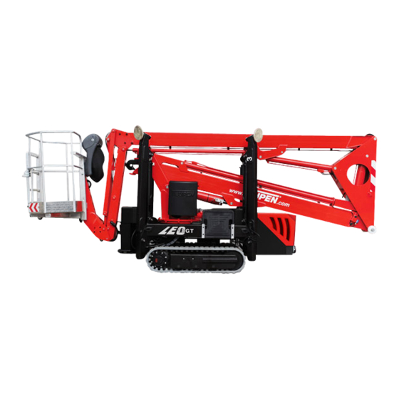
17.7 m height /Leo 18GT/ with low operating cost in abso- lute safe and comfort. The type Teupen Leo 18 GT is a elevating machine, which is equipped with one electro hydraulic control, as well as, it is self-powered elevating machine with cage and built-on a rrubber caterpillar and it can be operated with simple handling. -
Page 4: The Function And Fabrication
1.THE FUNCTION AND FABRICATION 1.1 The function The Teupen Leo 18 GT elevating machine with cage can be used for elevating of persons and devices. The total load can be maximum 200 kg, which value is limited and calculated for the cage. -
Page 5: Technical Data
43/5 Version: Leo 18 GT_GB_02-2008 1.2 Technical data Working height: (remote control): 17.6 (17,90) m Platform height: (remote control): 15.6 (15,90) m Lateral outreach: approx. 7,60 m Safe load on cage: max. 200 kg Range of rotation: 355° Size of working cage (LxWxH): 1,2 x 0,7 x 1,1 m Length in travelling position with the cage: min. - Page 6 Upper lifting cylinder Parallel guide Telescope cylinder Bottom telescope Bottom telescope cylinder Vertical arm levelling cylinder Chart 1 The main part of the Leo 18 GT cage-elevating machine Chart 2 The moving diagram of the Leo 18 GT self-powered cage-elevating machine...
-
Page 7: General Description
43/7 Version: Leo 18 GT_GB_02-2008 1.3 General description 1.3.1 Frame and the supports The frame made of closed steel profile, which will carry: • the hydraulic supports, • the ground plates, the ground supporting observation system with the end- switch •... -
Page 8: Working Cage
43/8 Version: Leo 18 GT_GB_02-2008 1.3.4 Working cage The serial equipment is the demountable cage. The working area / basket / is a welded structure from aluminum profiles and plates. The entering to the cage can be by a turning down aluminum stairs. An and the two joining eyelet for tightening the safety automatically closing door belt... -
Page 9: Safety Instructions
43/9 Version: Leo 18 GT_GB_02-2008 1.3.7. Safety instructions This elevating machine is constructed considering the latest safety regulations. Notwithstanding the machine can cause personal injuries or other damages, therefore operating the machine is allowed only in case of functional operating and unexceptionable operation of the safety devices. -
Page 10: Meaning Of The Warning And Informative Signs Placed On The Machine
43/10 Version: Leo 18 GT_GB_02-2008 1.3.8 Meaning of the warning and informative signs placed on the machine: Persons not permitted in Max. lateral force 400 Min. 18 year old the cage during transport! Getting in and out of the cage over Avoid sudden move!! the rail is prohibited! Over 12, 5 m / sec wind force (grade 6) - Page 11 43/11 Version: Leo 18 GT_GB_02-2008 Wear safety hat! Do not operate machinery if Danger to fingers! temperature is below -15 Cº! Danger! 230 V Do not operate machinery Use safety belt! in dark! Warning! Engine shall be shut off before refuelling! Do not clean with high- pressure cleaner!
- Page 12 43/12 Version: Leo 18 GT_GB_02-2008 ATTENTION! Remove the plastic wheel after use. Safe storage of the plastic wheel should be ensured at the hydraulic valves. WARNING! If the basket sensor or any stabilizing sensor give alarm signal during operation (red light lights up on the control panel of the basket), the elevating machine can only be moved to the trans- port direction and the machine is only allowed to use for lifting after eliminating the operating trouble.
-
Page 13: Directives Of Safety Engineering And Environment Protection
43/13 Version: Leo 18 GT_GB_02-2008 2. DIRECTIVES OF SAFETY ENGINEERING AND ENVIRONMENT PROTECTION Safety engineering • Do not exceed the maximum load of the cage! • In any height, extra load is put or that extra person entries to the basket of the elevating machine from any aim must be prohibited. -
Page 14: Environmental Directives
43/14 Version: Leo 18 GT_GB_02-2008 2.2 Environmental directives • Hydraulic oil, which is in the elevating machine, contaminates the environmental that is why. if the oil leaks, it must be eliminated at once. If the sealing is damaged, the machine must not used. •... -
Page 15: Hydraulic Running Gear For The Rubber Caterpillar Tracks
43/15 Version: Leo 18 GT_GB_02-2008 3. HYDRAULIC RUNNING GEAR FOR THE RUBBER CATERPILLAR TRACKS 3.1 Elevation adjustment of the running gear WARNING! TIPPING DANGER! Elevation adjustment of the runnung gear must always be done by at least two persons. Supports shall be adjusted properly to avoid tipping (Maximum angle to crosswise direction is 10°... -
Page 16: Safety Devices
43/16 Version: Leo 18 GT_GB_02-2008 Photo from profiles which are arranged “A” form and from the securing pins 3.1.3 Safety devices The safety operating of the machine is controlled by the following safety systems • Check valves which are controlled by pressure and placed on all working cylinder •... -
Page 17: Handling And Usage Of The Machine
43/17 Version: Leo 18 GT_GB_02-2008 ATTENTION! The adjusting and the fasten bolted connections of the safety devices are fixed with paint or lead by the manufacturer. These fixations can be broken up by the owner or operating only for his or her own danger or responsibility. The manufacturer will not undertake responsibility for those warranty and accident consequents which have originated from the breaking up. - Page 18 43/18 Version: Leo 18 GT_GB_02-2008 The arms of the elevating machine are in basic position (arms are in bottom position, telescope is in pulled in position) The supports are in a pulled up position Safety key switch is switched off, and unplugged, ignition switch of the explosive engine is switched off and unplugged, top cover of the switching board is locked, machine is disconnected from the mains current,...
-
Page 19: The Requirements For The Operator
43/19 Version: Leo 18 GT_GB_02-2008 Movement on ramp: Slope of the ramp can be maximum 20º (36%) Before beginning of the transporting, you must check absolutely as follows • The connecting of the fixing-stretcher beltings • The tension of the fixing-stretcher beltings ATTENTION! The elevating machine, which is on the platform of the transporting vehicle, will change the running properties of the... -
Page 20: To Be In Operation
43/20 Version: Leo 18 GT_GB_02-2008 4.3 To be in operation Before starting up, you must comply the following regulations The damage, breaks, oil flow, cable break on the machine or extension cable is not damage must be checked. You must check whether there is any equipment or anything else utilities during voltage in functional area of the machine, which can endanger the work. -
Page 21: The Installation Of The Power Supply Of The Machine
43/21 Version: Leo 18 GT_GB_02-2008 4.4.2 The installation of the power supply of the machine Starting of the Honda engine • The filling up of fuel tank of the explosive engine • The switching in of electric supply of the Honda engine (O → I) Starting of the Honda 2. - Page 22 43/22 Version: Leo 18 GT_GB_02-2008 II. Starting the Honda engine from the basket: HONDA start 1. Start-Stop Honda engine 3. Emergency STOP 2. Honda choke pushbutton + green lamp 4. Key switch a., Switch on the key switch (4) b., To start the cold engine, push the choke button (2) , during starting with the start button (1).
- Page 23 43/23 Version: Leo 18 GT_GB_02-2008 2. Starting of the Kubota engine (Option) The filling up of fuel tank of the explosive engine The switching in of electric supply of the Kubota engine (3) (O → I) I. Ignition of the explosive engine from the bottom Starting up/stopping the KUBOTA ENGINE (option), you can do it with the turning switch which can be found a., Starting up/stopping the KUBOTA ENGINE (option), you can do it...
- Page 24 43/24 Version: Leo 18 GT_GB_02-2008 Ignition of the Kubota engine from the basket: 8. Time control start push button and green 1. Start-Stop lamp Kubota engine 3. Emergency stop 2. Oil pressure alarm 4. Key switch The alarm STOP-switch stops immediately the explosive engine, you can restart after the discoupling the STOP-switch.
-
Page 25: Traveling With The Machine
43/25 Version: Leo 18 GT_GB_02-2008 4.4.3 Traveling with the machine Movement of tha lifting machine can be directed from the basket and from the ground as well after demounting the basket.. a., Travelling control from the basket: The required direction must be chosen by the hydraulic regulating valves of the self- powered and those must be operated progressively. - Page 26 43/26 Version: Leo 18 GT_GB_02-2008 Emergency stop Caterpillar track: Left side Caterpillar track: Right side the operating of the machine can be broken off any time with the EMERGENCY-STOP button, which is placed on control panel. The safe directions for self-powering: ATTENTION! Tipping Danger! Maximal angle is to crosswise direction 10°...
-
Page 27: Stabilizing Of The Machine
43/27 Version: Leo 18 GT_GB_02-2008 4.4.4. Stabilizing of the machine The support control can be controlled from the basket or from the ground: • Place the machine in horizontal position with the hydraulic control valves • Set the selection switch (11) of the control panel to the stabilizing (quick moving) position. -
Page 28: The Control And The Operating Of The Superstructure
43/28 Version: Leo 18 GT_GB_02-2008 4.4.5 The control and the operating of the superstructure: • In case of the right fixing of the basket, see 4.4.1 and the suitable stabilization, see 4.4.4. and, only after that, the superstructure can be operated by the josticks. •... -
Page 29: Emergency Control
43/29 Version: Leo 18 GT_GB_02-2008 periodic movements (especially in case of the operation of the optional electric motor ). • Levelling of the vertical arm and the cage shall be executed before any movements of the bottom arm (controlled by the joystick). •... - Page 30 43/30 Version: Leo 18 GT_GB_02-2008 III. Stabilization, travelling, emergency control: • Proportional valves (D) should be pushed in totally, then should be locked after turning right. • Bullet valve (A), located besides the hand pump, should be opened (vertical position). •...
-
Page 31: Working On The Slope
43/31 Version: Leo 18 GT_GB_02-2008 Sequential contol of the bottom WARNING arm and the bottom telescope FIGYELEM! shall be executed with special OVERTURING DANGER! care: BORULÁSVESZÉLY! Pushing down the bottom arm is Az alsókar lefelé mozgatása csak only allowed after pulling the - First the bottom telescope a teleszkóp alaphelyzetbe való... -
Page 32: Instructions For Operating In Winter
43/32 Version: Leo 18 GT_GB_02-2008 The selecting and placing of the backings, you must take into consideration the following conditions: • The load of the supports can be each about 13.55 kN • The hydraulic supports are stressed by dynamic load for example from the rotation of the boom and elevation dynamic effects of the superstructure which gives away it to the soil. -
Page 33: Maintenance And Lubrication Of The Machine
We emphatically underline, that the beforehand mentioned works are executed by such kind of person who does not belong to the acknowledged expert of the Teupen Hungaria company, we will refuse all warranty demand and all responsibility which formed from the... -
Page 34: Lubrication And Checking Tasks
43/34 Version: Leo 18 GT_GB_02-2008 If the elevating machine damages, a damage report must be made by a damage-expert with the countersigns of two evidences. WARNING! The adjusting and the fasten bolted connections of the safety devices are fixed with paint or lead by the manufacturer. These fixations can be broken up by the owner or operating only for his or her own danger or responsibility. -
Page 35: Bogie Maintenance Instruction
43/35 Version: Leo 18 GT_GB_02-2008 5.1.2 Bogie maintenance instructions Control the tightening screws Screws shall be retightened after 700 running hours or at least in every sixth month to avoid any injuries or damages. Control the pull-on torque of the screws after the first 100 running hours to avoid possible malfunctions. - Page 36 43/36 Version: Leo 18 GT_GB_02-2008 Check the bearings: Any small chips in the system can modify working of the bearings, therefore bearing shall be checked regularly. Bearings shall be checked in every 2000 running hours but at least once a year Missing the above mentioned checks causes damages and injuries during operating Lubrication of the bogie:...
- Page 37 The execution of the load test checking hollow screw tightness of the bogie The oil must be changed in the machine once a year. The Teupen Hungária Company or the acknowledged special companies of the Teupen Hungaria Company should achieve the annual checking tasks.
- Page 38 43/38 Version: Leo 18 GT_GB_02-2008 A-weekly B-once a year Chart 5 Grease On the given points of the elevating machine, there are lubricating places with lubricating nipples which ones are able to move on each another. See the chart 5. The lubricant type, which you can use, the following table contains: The quality of the lubricant The applied temperature...
- Page 39 43/39 Version: Leo 18 GT_GB_02-2008 Oil level: The level of the hydraulic equipment only can be checked, if the cylinders are in basic position or the machine is in delivery position. If it necessary, the oil must be filled up. The different type oil mixing is prohibited because it can cause the damage of the machine.
- Page 40 43/40 Version: Leo 18 GT_GB_02-2008 Gearbox lubrication (on the both sides of the machine ) Level and fitting plug Oil level Drain plug The checking of the oil level and state and, if it necessary, it must be refilled: Monthly The oil change must be carried out after the first 150 hours of work, and then once a year.
-
Page 41: Operating Trouble And Prevention Of Those
43/41 Version: Leo 18 GT_GB_02-2008 5.2 Operating trouble and prevention of those FAILURE THE CAUSE OFTHE FAILURE CORRECTION FAILURE The hydraulic pump The valve of the hand Turn right for closing cannot generate pump is open pressure. The pressure limiting valve Call the customer service of the control block is contaminated... -
Page 42: The Maintenance Of The Explosive Engine
43/42 Version: Leo 18 GT_GB_02-2008 Vertical arm is not Instantaneous cutout. - Swich the machine off. levelled during the - Adjust the normal operation of the bottom position of the basket by arm. Inclination (10 the hand pump to ensure degree) of the vertical the vertical position of the arm stops the machine... - Page 43 Teupen Hungaria GmbH H-8992 Bagod, Gepallomas Str. 9 Telephone: 00 36 92 560-160 Fax: 00 36 92 460-800 E-Mail: info@teupenhungaria.com Internet: www.teupenhungaria.com Importeur: B. Teupen Maschinenbau GmbH Marie-Curie-Straße 13 D-48599 Gronau / Germany Telephone: +49(0)2562/8161-0 Fax: +49(0)2562/8161-888 E-Mail: info@teupen.de Internet: www.teupen.de...