Table of Contents
Advertisement
Quick Links
Advertisement
Table of Contents

Related Manuals for Furuno CSH-53


Summary of Contents for Furuno CSH-53
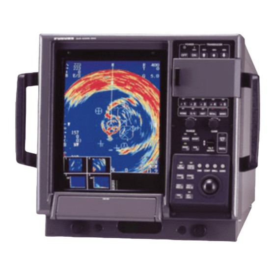
- Page 1 COLOR SCANNING SONAR CSH-53 MODEL...
- Page 2 Y o u r L o c a l A g e n t / D e a l e r 9 - 5 2 , A s h i h a r a - c h o , N i s h i n o m i y a , J a p a n T e l e p h o n e : 0 7 9 8 - 6 5 - 2 1 1 1 T e l e f a x :...
- Page 3 SAFETY INSTRUCTIONS CAUTION WARNING Ground the equipment to Do not open the cover prevent electrical shock and unless totally familiar with mutual interference. electrical circuits. Hazardous voltage which will Use the proper fuse. cause death or serious injury exists inside the equipment. Use of a wrong fuse can result in fire or permanent equipment damage.
-
Page 4: Table Of Contents
TABLE OF CONTENTS 1. SYSTEM CONFIGURATION ............1 2. EQUIPMENT LISTS ................ 2 3. MOUNTING THE EQUIPMENT 3.1 Mounting the Hull Unit ....................4 3.2 Mounting the Display Unit .................... 9 3.3 Mounting the Transmitter Unit ..................10 3.4 Mounting the Interface Unit ..................10 3.5 Grounding the Equipment ................... -
Page 5: System Configuration
1. SYSTEM CONFIGURATION STANDARD OPTION REMOTE DISPLAY SUB DISPLAY REMOTE CONTROL BOX CSH-106 CSH-536 CSH-135 DISPLAY UNIT CSH-530 SHIP'S MAINS 100 VAC, 1φ, SHIP'S MAINS 50/60 Hz 100 VAC, 1φ, 50/60 Hz TRANSMITTER UNIT CSH-551 110/115/220/230 VAC, 1φ, 50/60 Hz STEP-DOWN TRANSFORMER INTERFACE UNIT... -
Page 6: Equipment Lists
2. EQUIPMENT LISTS Standard Supply t e l . g t t t i l l a i t a s t r Optional Equipment . t s i t c i t c (Continued on next page) - Page 7 Optional Equipment (con’t) t l i — t t i — t t i — t t i t t i — t t i — t t i — t t i — t t i — t t i —...
-
Page 8: Mounting The Equipment
3. MOUNTING THE EQUIPMENT 3.1 Mounting the Hull Unit Location of hull unit Discussion and agreement are required with the dockyard and the shipowner in deciding the location of the hull unit. When deciding the location, the following points should be taken into account. - Page 9 Heater Heat insulator Figure 3-2 Maintenance space, example sonar compartment...
- Page 10 Shortening the retraction tank The retraction tank is 900 mm in length when supplied. Shorten the tank as necessary so that the transducer is placed well below the keel when it is lowered. The following table provides guidelines for shortening the tank. Refer also to the retraction tank installation drawing at the back of this manual.
- Page 11 Installing hull unit on retraction tank After welding the retraction tank and allowing sufficient time for cooling, install the hull unit as follows: 1. Clean the hull unit flange, the O-ring and O-ring groove and coat them with a slight amount of grease.
- Page 12 Installing stays (anti-vibration measure) Install stays from the top of the hull unit to the ship’s hull. The stays should be angle iron with a size of 75 x 75 x 9 mm or more and at least two pieces should be used; one each to ship’s bow and stern directions.
-
Page 13: Mounting The Display Unit
3.2 Mounting the Display Unit The display unit is designed for tabletop mount- ing. Mount it in the steering house, considering the following conditions: • Place where operating personnel are able to control the unit easily while observing the fishing ground or the area surrounding the vessel. -
Page 14: Mounting The Transmitter Unit
3.3 Mounting the Transmitter Unit The transmitter unit can be mounted with or without mounting legs. For use without mounting legs remove them and use inside mounting holes. The transmitter unit should be reinforced against vibration by stays extending from the eye- bolts on the top of the unit. -
Page 15: Grounding The Equipment
3.5 Grounding the Equipment Since all units are very sensitive to noise, they should be grounded with a suitable copper strap or ground wire. The location of the ground terminal of each unit is shown below. CAUTION Ground the equipment to prevent electrical shock and mutual interference. -
Page 16: Wiring
4. WIRING 4.1 How to Use the Crimping Tool, Pin Extractor A special crimping tool is necessary for connection of wires to the contact pins of the 38P connector. Also a pin extractor should be used to remove the contact pin from the connector body. -
Page 17: Location Of Connectors, Terminal Boards
4.2 Location of Connectors, Terminal Boards Remote Control Display Unit CN-A13 CN-A5 Interface Unit CN-A1 27cm 20cm 10S1258-1 f 18 (Max. 20m) External Device DPYCY-1.25 Ship's Mains 100VAC, 50/60Hz S10-10-20 (38P) (10S1258-1) f 18 Max. 80m Transmitter Unit *1: After connecting cables, cover cable clamp with putty. -
Page 18: Assembling Connectors At Transmitter Unit
4.3 Assembling Connectors at Transmitter Unit Fabricating cable S10-11-20 or S10-12-20 Figure 4-3 Fabrication of cable S10-11-20, S10-12-20 Assembling the 38P connector 1. Bundle unused wires outside the connector case. 2. Fix the cover 1, noting the cable outgoing direction. 3. - Page 19 S10-11-20 (38P) Color Color Color [10S1258-1] BLK/BRN BLK/PPL BRN/GRN BLK/RED BLK/GRY BRN/BLU BLK/ORG BLK/WHT BRN/PPL BLK/YEL BRN/RED BRN/GRY BLK/GRN BRN/ORG BRN/WHT BLK/BLU BRN/YEL RED/ORG S10-12-20 (38P) Color Color Color [10S1260] YEL/BLK RED/WHT YEL/PPL BLU/BLK GRN/WHT BLU/PPL RED/BLK YEL/GRY RED/PPL GRN/BLK BLU/GRY GRN/PPL YEL/WHT...
-
Page 20: Connection Of Transducer Cable
Cable DPYCY-3.5 M4 (YEL) x 2 Armor Anticorrosive Armor Vinyl sheath sheath Conductor Vinyl S = 3.5 mm Note: DPYCY-3.5 is Japan standard cable. sheath ø = 2.4 mm Use equivalent cable. Figure 4-6b Fabrication of cable DPYCY-3.5 4.4 Connection of Transducer Cable The transducer cables are prefitted with connectors. -
Page 21: Attaching Power Cable Connector Ncs-253P
Figure 4-8 Attachment of power supply cable connector 4.6 Synchronizing Transmission with Other Sonars, Echo Sounders To synchronize the transmission of the CSH-53 with that of other sonars or echo sounders, do the following. Wiring a) For current driven KP... -
Page 22: Connection Of Interface Unit Cs-120A
5. CONNECTION OF INTERFACE UNIT CS-120A If the CSH-53 is combined with nav sensor (via Interface Unit CS-120A) and fishing equip- ment, its function is expanded to include true motion presentation, echo sounder picture, FNZ marker presentation, etc. This chapter provides the methods of interfacing the CSH-53 sonar with other equipment and wiring details. -
Page 23: Connections For Es Picture And Fnz Markers
5.2 Connections for ES Picture and FNZ Markers To provide echo sounder picture and FNZ markers, connect echo sounder to J203 and net sonde to J202. The signals applied to J202 and J203 are J202: Net sonde signal and trigger signal (keying pulse of echo sounder). A white line signal from an echo sounder may be additionally applied as described on page 4-5 if the digital depth data is not available on J204. -
Page 24: Connections For Digital Readout Of Position, Water Temperature And Depth
Connection 3: Displaying echo sounder picture and FNZ markers by separate echo sounders Figure 5-4 Connections for echo sounder picture and FNZ markers by separate echo sounders 5.3 Connections for Digital Readout of Position, Water Temperature and Depth The data for these readouts are taken from the equipment shown in the table below and input to J204. -
Page 25: Wiring
Note: When a color video sounder which has digital depth data output is not available, the white line signal of a paper recording echo sounder can be used to provide digital depth read- out. Connect the echo sounder as shown below or as shown in connection 2 or 3 in paragraph 5.2 and operate the echo sounder front panel controls so that the white line is effected on the seabed contour. - Page 26 Connector Figure 5-7 Assembling connector Positioning guide pins Table 5-2 Guide pins and connector Connector Guide Pin Setting Tool J201 CN-A5 Guide Pin Guide Pin A (Large) Guide Pin B (Small) Type 10-910-0179-0 Connection with external device Wire Meaning 02S8040 Symbol Color Vinyl sheath wire...
- Page 27 Fabrication, assembling 10P and 7P connectors 10P Connector (SRCN6A16-10P) J202 (FNZ), J204 (CIF), J205 (GYRO), J207 (CIF) 7P Connector (SRCN6A16-7P) J203 (ES) Figure 5-9 Fabrication of 10P, 7P connectors...
-
Page 28: Changing Power Specifications
6. CHANGING POWER SPECIFICATIONS The transmitter unit is shipped ready for connection to ship’s mains of 100 VAC. For 110/115/ 200/220/230 VAC, change transformer taps as shown below. The display unit is designed for 100 VAC operation only. For 110 VAC or 220 VAC, use step- down transformer PT-400 (optional supply). -
Page 29: Installation Of Frp Retraction Tank
• Use only the tank supplied. • Follow the instructions in this chapter. • If the owner of the equipment elects to use a shipyard-prepared FRP tank, FURUNO will assume no responsibility for any damage caused by water leakage. In this case do the fol- lowing: •... -
Page 30: Installation Of The Frp Retraction Tank
7.2 Installation of the FRP Retraction Tank Fasten the hull unit to the retraction (after installing the retraction tank) as follows. 1. Clean the surface of the tank flange. Coat the flange with about 1 mm thickness of sealant (Three Bond 1101, supplied). Note: Use only the sealant supplied. - Page 31 5. Before setting the hull unit on top of the retraction tank, observe the following cautions: • Clean the hull unit flange to make sure no foreign material falls into the retraction tank. Bolt • Confirm that waterproofing gasket is in place. hole Figure 7-5 Tank flange 6.
-
Page 32: Adjustment And Check
8. ADJUSTMENT AND CHECK 8.1 Hull Unit Check 1. Press the ON switch to turn on the equipment. Con- firm that the lamps above the ON and c switches POWER TRANSDUCER light. 2. Confirm that the 5V and UP lamps on the raise/ lower control box are lit. -
Page 33: Heading Adjustment
11. Press the d switch. Confirm that the lamp above the switch blinks while the transducer is being lowered, a short beep sounds when the mid limit switch kicks, and the lamp lights when the transducer is fully lowered. 12 Press the c switch. Confirm that the lamp above the switch blinks while the transducer is being raised, a short beep sounds when the mid limit switch kicks, and the lamp lights when the transducer is fully raised. -
Page 34: Dip Switch Setting
3. Select HEADING ADJ. INIT SET/TEST MENU Select item with dc[ \ keys and press MENU key. Press END key to close menu. HEADING ADJ 359° Setting range: 0° to 359° Figure 8-4 HEADING ADJ menu 4. Enter heading correction with [ or \, referring to the table below for guidance. i t a i t c i t t... -
Page 35: Setting And Adjustment On The Interface Unit Cs-120A
PND Board (10P6714) " 5 " 1 8.4 Setting and Adjustment on the Interface Unit CS-120A Nav data and fish data input from external equipment can be turned on or off with DIP switch DP-1 in the Interface Unit CS-120A. Ship's speed and bearing (for track plotting, true motion, target lock, etc.) Input Device Select navigation which feeds... - Page 36 Interface Unit Adjustment E/S LEVEL control on the display unit at allows adjustment of the picture color on the screen. However, if adjustment of the E/S level control can not get the best coloration, perform fine adjustment with the preset potentiometers on the I/O board in the interface unit as follows. I/O 10P0047 R27 (W/L INHIBIT TIME) R36 (OFFSET)
- Page 37 sounder is used for depth information. Potentiometer R27 cancels the white line pulse for about 10 ms after transmission to avoid false depth indication caused by unwanted noise in short ranges. No readjustment of R27 is required as long as the CSH-73 indicates the correct depth. If the depth is wrong, turn R27 clockwise.
-
Page 38: When Ship's Mains Is 24 Vac
9. WHEN SHIP’S MAINS IS 24 VDC When the ship’s mains is 24 VDC, use DC/AC inverter unit TR-2435 and TR-24100 (optional supply). Specifications and interconnections are as follows. TR-2435 Display Unit CN-A15 24 VDC Ship's mains *DPYCY-1.25 *DPYCY-1.25 24 VDC 100 VAC TR-24100 POWER SUPPLY... -
Page 39: Spare Parts
Accessories Special Tools i t t Spare Parts...