Table of Contents
Advertisement
Quick Links
XP-ZV700/ZV701/ZV702
SERVICE MANUAL
Ver. 1.4 2005.10
US and foreign patents licensed from Dolby Laboratories.
•
SonicStage and SonicStage logo are trademarks or registered trademarks of Sony Corporation.
OpenMG, Net MD, ATRAC, ATRAC3plus and their logos are trademarks of Sony Corporation.
•
"WALKMAN" is a registered trademark of Sony Corporation to represent Headphone Stereo
•
products.
is a trademark of Sony Corporation.
•
Microsoft, Windows, Windows NT and Windows Media are trademarks or registered trademarks of
Microsoft Corporation in the United States and /or other countries.
IBM and PC/AT are registered trademarks of International Business Machines Corporation.
•
Macintosh is a trademark of Apple Computer, Inc. in the United States and/or other countries.
•
Pentium is a trademark or a registered trademark of Intel Corporation.
•
All other trademarks and registered trademarks are trademarks or registered trademarks of their
respective holders. ™ and ® marks are omitted in this manual.
CD and music-related data from Gracenote, Inc., copyright © 2000-2003 Gracenote. Gracenote
•
CDDB® Client software, copyright 2000-2003 Gracenote. This product and service may practice
one or more of the following U.S. Patents: #5,987,525; #6,061,680; #6,154,773, #6,161,132,
#6,230,192, #6,230,207, #6,240,459, #6,330,593, and other patents issued or pending.
Gracenote and CDDB are registered trademarks of Gracenote. The Gracenote logo and logotype,
the Gracenote CDDB logo, and the "Powered by Gracenote" logo are trademarks of Gracenote.
Program © 2001, 2002, 2003, 2004 Sony Corporation
Documentation © 2004 Sony Corporation
AEP model
Sony Corporation
9-879-387-05
Personal Audio Division
2005J05-1
Published by Sony Engineering Corporation
© 2005.10
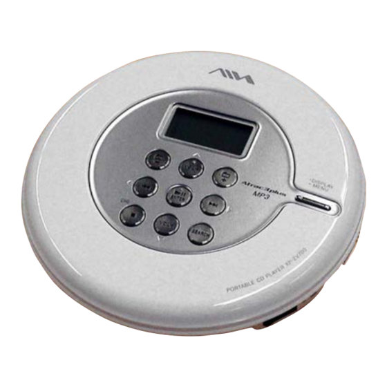
Photo: XP-ZV700
Model Name Using Similar Mechanism
CD Mechanism Type
Optical Pick-Up Name
SPECIFICATIONS
,
120 V, 60 Hz (MX model)
220 V, 50 Hz (AR model)
230 V, 50 Hz (HK model)
240 V, 50 Hz (AUS model)
100 V-240 V, 50/60 Hz (Other models)
: AEP
AEP Model
XP-ZV700/ZV701/ZV702
E Model
XP-ZV700/ZV701
Australian Model
NEW
CDM-3325ERV
DAX-25EV
– Continued on next page –
PORTABLE CD PLAYER
XP-ZV700
.
Advertisement
Table of Contents

Related Manuals for Aiwa XP-ZV700


Summary of Contents for Aiwa XP-ZV700
-
Page 1: Specifications
Ver. 1.4 2005.10 E Model XP-ZV700/ZV701 Australian Model XP-ZV700 Photo: XP-ZV700 US and foreign patents licensed from Dolby Laboratories. Model Name Using Similar Mechanism • SonicStage and SonicStage logo are trademarks or registered trademarks of Sony Corporation. OpenMG, Net MD, ATRAC, ATRAC3plus and their logos are trademarks of Sony Corporation. -
Page 2: Table Of Contents
XP-ZV700/ZV701/ZV702 Ver. 1.2 TABLE OF CONTENTS SERVICING NOTES ..........3 : AEP GENERAL ..............5 DISASSEMBLY 3-1. Disassembly Flow ............6 3-2. Cabinet (Upper) Assy, Cabinet (Lower) ......6 3-3. JACK Board, Optical Pick-up Assy (CDM-3325ERV) ... 7 3-4. SWITCH Board ............... 7... -
Page 3: Servicing Notes
XP-ZV700/ZV701/ZV702 Ver. 1.4 SECTION 1 SERVICING NOTES LASER DIODE AND FOCUS SEARCH OPERATION NOTES ON HANDLING THE OPTICAL PICK-UP CHECK BLOCK OR BASE UNIT During normal operation of the equipment, emission of the laser The laser diode in the optical pick-up block may suffer electrostatic... - Page 4 XP-ZV700/ZV701/ZV702 Ver. 1.2 Providing the required system environment System requirements The following system environment is required in order to use the SonicStage Ver. 2.3. Computer IBM PC/AT or Compatible • CPU: Pentium II 400 MHz or higher (Pentium III 450 MHz or higher is recommended.)
-
Page 5: General
XP-ZV700/ZV701/ZV702 SECTION 2 This section is extracted from instruction manual. GENERAL SEARCH button Guide to Parts and CD player: Controls ZV700: AEP model: button CD player Other models: /CHG button 12 345 Remote: button CD player: (play/pause)*/ENTER button Remote: (play/pause)* button >... -
Page 6: Disassembly
XP-ZV700/ZV701/ZV702 SECTION 3 DISASSEMBLY • This set can be disassembled in the order shown below. 3-1. DISASSEMBLY FLOW 3-2. CABINET (UPPER) ASSY , CABINET (LOWER) 3-4. SWITCH BOARD (Page 6) (Page 7) 3-3. JACK BOARD, OPTICAL PICK-UP ASSY (CDM-3325ERV) (Page 7) Note: Follow the disassembly procedure in the numerical order given. -
Page 7: Jack Board, Optical Pick-Up Assy (Cdm-3325Erv)
XP-ZV700/ZV701/ZV702 3-3. JACK BOARD, OPTICAL PICK-UP ASSY (CDM-3325ERV) 5 optical pick-up assy 4 insulator (CDM-3325ERV) 2 two connectors (CN401, CN402) 4 insulator 4 insulator 1 OP flexible board (CN601) 3 JACK board 3-4. SWITCH BOARD 9 button (operation) 8 button (menu) -
Page 8: Diagrams
XP-ZV700/ZV701/ZV702 Ver. 1.3 SECTION 4 DIAGRAMS • Note for Printed Wiring Boards and Schematic Diagrams Note on Printed Wiring Boards. Note on Schematic Diagrams. • All capacitors are in µF unless otherwise noted. (p: pF) • X : parts extracted from the component side. -
Page 9: Printed Wiring Board - Egl Board
XP-ZV700/ZV701/ZV702 Ver. 1.4 :Uses unleaded solder. 4-1. PRINTED WIRING BOARD – EGL BOARD – JACK BOARD CN501 EGL BOARD EGL BOARD (SIDE B) (SIDE A) (Page 11) R407 CN9002 IC1602 R606 R406 VDR601 C639 C676 C675 R632 ZV700: E18, E33, MX, HK,... -
Page 10: Schematic Diagram - Egl Board
XP-ZV700/ZV701/ZV702 Ver. 1.4 4-2. SCHEMATIC DIAGRAM – EGL BOARD – • See page 16 for Waveforms. • See page 16 for IC Pin Function Description. CN601 OPGSW FE(A) C695 R634 SE(B) 4700p RB601 C648 C650 C653 4700p 0.47 C602 R628... -
Page 11: Jack Board (Component Side)
XP-ZV700/ZV701/ZV702 Ver. 1.1 :Uses unleaded solder. 4-3. PRINTED WIRING BOARD – JACK BOARD (COMPONENT SIDE) – M401 M402 (SPINDLE) R410 D401 • Semiconductor (SLED) C401 Location Ref. No. Location C418 Q404 JACK BOARD C410 (COMPONENT SIDE) D302 D401 R416 D402... -
Page 12: Jack Board (Conductor Side)
XP-ZV700/ZV701/ZV702 Ver. 1.1 :Uses unleaded solder. 4-4. PRINTED WIRING BOARD – JACK BOARD (CONDUCTOR SIDE) – JACK BOARD (CONDUCTOR SIDE) (EXCEPT ZV700: AEP) DRY BATTERY RECHARGEABLE SIZE “AA” BATTERY (IEC DESIGNATION LR6) NH-7WMAA 1PC 1.2V 700 mAh 1PC 1.5V (NH-AA-B2D 1PC 1.2V 2300 mAh) -
Page 13: Schematic Diagram - Jack Board
XP-ZV700/ZV701/ZV702 Ver. 1.1 4-5. SCHEMATIC DIAGRAM – JACK BOARD – • See page 16 for Waveforms. • See page 16 for IC Block Diagram. • See page 16 for IC Pin Function Description. CN501 GND_AU SP_DTC/TSB AD_RMKEY AD_RMKEY CN601 DCINMNT... -
Page 14: Printed Wiring Board - Switch Board
XP-ZV700/ZV701/ZV702 :Uses unleaded solder. 4-6. PRINTED WIRING BOARD – SWITCH BOARD – SWITCH BOARD C1002 C1011 C1012 C1010 CN1001 VDR1001 C1001 LCD1001 LIQUID CRYSTAL DISPLAY S1001 S1009 S1002 S1007 DISPLAY – VOL+ MENU CN1002 R1104 JACK R1135 S1005 R1108 BOARD... -
Page 15: Schematic Diagram - Switch Board
XP-ZV700/ZV701/ZV702 4-7. SCHEMATIC DIAGRAM – SWITCH BOARD – CN1001 CN1002 R1001 CLK_I R1002 LCD_CS_I R1003 DATA_O R1004 DATA_I R1005 RSTB LCD_XRST VCC2_+2.1V C1001 VCC0_+2.7V (Page 13) VREF D_GND C1002 VCIN AD_KEY1 R1113 R1101 R1105 C1012 0.22 2.2k AD_KEY2 VDR1001 LCD1001... - Page 16 XP-ZV700/ZV701/ZV702 Ver. 1.4 • IC Pin Function Description EGL BOARD IC603 CXR711260-218H2 (SYSTEM CONTROLLER, DSP, LCD DRIVER) Pin No. Pin Name Description • IC Block Diagram PE6/SI1 Serial data input from the liquid crystal display – JACK Board – PE5/SO1...
- Page 17 XP-ZV700/ZV701/ZV702 Pin No. Pin Name Description Not used 57, 58 SDA8, SDA9 Address signal output to the SD-RAM Not used 60, 61 SDA7, SDA6 Address signal output to the SD-RAM Not used 63, 64 SDA5, SDA4 Address signal output to the SD-RAM...
- Page 18 XP-ZV700/ZV701/ZV702 Pin No. Pin Name Description DAMPCLK Not used VDIOAMP Power supply terminal (+2.1V) PWML Not used PWMR Not used VSSAMP Ground terminal VSS7 Ground terminal AVDPLL0 Power supply terminal (+2.7V) AVSPLL0 Ground terminal VDIOPLL0 Power supply terminal (+2V) VSS8...
- Page 19 XP-ZV700/ZV701/ZV702 Pin No. Pin Name Description FILO Filter output terminal for master PLL FILI Filter input terminal for master PLL Charge pump output terminal for master PLL VSS12 Ground terminal DVDD3 Power supply terminal (+1.3V) VDIODSP Power supply terminal (+2V)
- Page 20 XP-ZV700/ZV701/ZV702 Pin No. Pin Name Description PD7/INT7 to 209 to 213 Not used PD3/INT3 PD2/INT2/ECIN FG signal input from the motor/coil drive PD1/INT1/T1 Beep signal output to the headphone amplifier PD0/INT0/EC0 Not used PE7/XSCS1 Command latch signal output to the liquid crystal display...
- Page 21 XP-ZV700/ZV701/ZV702 JACK BOARD IC401 SC901591AFR2 (FOCUS/TRACKING COIL DRIVE, SPINDLE/SLED MOTOR DRIVE, POWER CONTROL) Pin No. Pin Name Description Comparator (U/V/W) negative pole input terminal Power supply terminal (for spindle motor drive U phase) Spindle motor drive U phase output terminal...
- Page 22 XP-ZV700/ZV701/ZV702 Pin No. Pin Name Description VG power supply output terminal (+5V) Not used CINP Battery charge circuit error amplifier non-invert input for rechargeable battery Capacitor connection terminal for charge pump (high side) of VG power supply circuit Capacitor connection terminal for charge pump (low side) of VG power supply circuit...
-
Page 23: Exploded Views
XP-ZV700/ZV701/ZV702 Ver. 1.2 SECTION 5 EXPLODED VIEWS NOTE: • -XX and -X mean standardized parts, so they • Color Indication of Appearance Parts The components identified by mark 0 or may have some difference from the original Example: dotted line with mark 0 are critical for safety. -
Page 24: Cabinet (Upper) Assy Section
XP-ZV700/ZV701/ZV702 Ver. 1.2 5-2. CABINET (UPPER) ASSY SECTION not supplied LCD1001 SWITCH board Ref. No. Part No. Description Remark Ref. No. Part No. Description Remark X-2050-970-1 CABINET (UPPER) SUB ASSY (W) (WHITE) X-2050-978-1 CABINET (UPPER) SUB ASSY (B) (BLACK) (ZV700: E18, E33, MX, HK, AR, AUS) -
Page 25: Cabinet (Lower) Section
XP-ZV700/ZV701/ZV702 Ver. 1.4 5-3. CABINET (LOWER) SECTION CDM-3325ERV not supplied JACK board When EGL board is replaced or EEPROM (IC1602) on the EGL board is replaced, patch processing is needed. Confirm about information of patch processing to each service headquarters. -
Page 26: Optical Pick-Up Section (Cdm-3325Erv)
XP-ZV700/ZV701/ZV702 5-4. OPTICAL PICK-UP SECTION (CDM-3325ERV) M401 M402 Ref. No. Part No. Description Remark Ref. No. Part No. Description Remark 3-318-203-61 SCREW (B1.7X4), TAPPING 3-221-475-01 SHAFT, STANDARD 0 152 X-3383-995-1 OPTICAL PICK-UP (DAX-25EV) 3-222-298-01 RACK 3-221-473-01 COVER, GEAR 3-222-299-01 SPRING, RACK RETAINER 3-221-472-02 CHASSIS 3-348-998-31 SCREW (M1.4X2.5), TAPPING, PAN... -
Page 27: Electrical Parts List
XP-ZV700/ZV701/ZV702 Ver. 1.4 SECTION 6 ELECTRICAL PARTS LIST NOTE: • Due to standardization, replacements in the • Items marked “*” are not stocked since they The components identified by mark 0 or dotted line with mark 0 are parts list may be different from the parts are seldom required for routine service. - Page 28 XP-ZV700/ZV701/ZV702 Ver. 1.3 JACK Ref. No. Part No. Description Remark Ref. No. Part No. Description Remark R649 1-218-969-11 RES-CHIP 1/16W R650 1-218-977-11 RES-CHIP 100K 1/16W C409 1-137-710-11 CERAMIC CHIP 10uF 6.3V R651 1-218-977-11 RES-CHIP 100K 1/16W C410 1-128-003-11 ELECT CHIP...
- Page 29 XP-ZV700/ZV701/ZV702 Ver. 1.1 JACK Ref. No. Part No. Description Remark Ref. No. Part No. Description Remark D406 6-500-483-01 DIODE MA22D2800LS0 Q404 6-551-139-01 TRANSISTOR DTC115TE-TL D407 6-500-540-01 DIODE RB521S-30FTE61 Q408 8-729-055-85 TRANSISTOR UMT1N-TN D408 6-500-540-01 DIODE RB521S-30FTE61 D411 8-719-071-87 DIODE MA785- (TX), SO...
- Page 30 XP-ZV700/ZV701/ZV702 Ver. 1.2 JACK SWITCH Ref. No. Part No. Description Remark Ref. No. Part No. Description Remark R443 1-216-837-11 METAL CHIP 1/10W R1106 1-216-829-11 METAL CHIP 4.7K 1/10W R451 1-216-845-11 METAL CHIP 100K 1/10W R1107 1-216-833-11 METAL CHIP 1/10W R455...
- Page 31 XP-ZV700/ZV701/ZV702 Ver. 1.2 Ref. No. Part No. Description Remark Ref. No. Part No. Description Remark 2-348-289-31 MANUAL (SS), INSTRUCTION (Installation/Operating Guide) (FRENCH) (ZV700: AEP/ZV701: AEP/ZV702) 2-348-289-41 MANUAL (SS), INSTRUCTION (Installation/Operating Guide) (GERMAN, ITALIAN, HUNGARIAN) AC power adaptor Earphones Earphones (ZV700: AEP/ZV701: AEP/ZV702)
-
Page 32: Revision History
Addition of Hong Kong, Argentina, Australian and New Zealand models to XP-ZV700 Revision of electrical parts 2005.04 Addition of Mexican model to XP-ZV700 2005.07 Deletion of Part No. for Ref. No. IC603 on EGL board and Deletion of Notes on replacement of Ref. No. IC603 Change of Part No.