Table of Contents
Advertisement
Quick Links
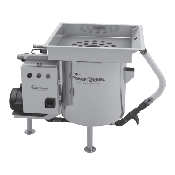
Installation, Care, and Use Manual
Standard (Model PRS)
Pot/Pan (Model PRP)
WARNING indicates a hazardous situation which, if not avoided, could result in
death or serious injury.
CAUTION indicates a hazardous situation which, if not avoided, could result in
minor or moderate injury.
NOTICE is used to address practices not related to physical injury.
Please be certain that the person who installs or uses this appliance carefully reads
and understands the Safety Instructions contained in this manual.
www.insinkerator.com/foodservice
Part No. 15392 Rev B
Advertisement
Table of Contents

Related Manuals for InSinkErator PowerRinse PRP Series


Summary of Contents for InSinkErator PowerRinse PRP Series
- Page 1 NOTICE is used to address practices not related to physical injury. Please be certain that the person who installs or uses this appliance carefully reads and understands the Safety Instructions contained in this manual. www.insinkerator.com/foodservice Part No. 15392 Rev B...
-
Page 2: Table Of Contents
Table of Contents Product Overview Introduction ..................3 System Components ................4 Typical Installation ................4 Required Tools/Materials ..............4 Table Cutout Dimensions ..............5 Installation Instructions Assembly..................6 Plumbing Water Connections ..............7 Adjusting Water Temperature ..........8 Drain Piping ................8 Electrical Electrical Disconnect Switch ..........8 Electrical Connections ............9 Initial Setup and Verification Prepare the System ...............9 Operating Instructions... -
Page 3: Product Overview
The PowerRinse Waste Collection System is CUL are for the benefit of the installing contractor. ® Listed when installed in conjunction with InSinkErator InSinkErator and/or InSinkErator Factory Authorized pumps and controls, and per the installation instructions Service Centers do not make original installations. For... -
Page 4: System Components
NOTICE is used to address practices not related to physical injury. Please be certain that the person who installs or uses this appliance carefully reads and understands the Safety Instructions contained in this manual. www.insinkerator.com/foodservice Part No. 15392 Rev A o Pipe wrench o 7/16"... -
Page 5: Table Cutout Dimensions
Product Overview 35.5" (902 mm) Pot/Pan (Model PRP) 23.75" (603 mm) Standard (Model PRS) The PowerRinse Waste Collection ® System pump motor fan must have a 10.75" minimum of 1" of clearance from any (273 mm) wall or obstruction in order to operate 21.5"... -
Page 6: Installation Instructions
(not provided by InSinkErator). CHANGING THE CONTROL LOCATION Optional – to relocate the control, remove and save four (4) bolts and nuts. -
Page 7: Plumbing
Installation Instructions ASSEMBLY (cont.) PLUMBING PROPERTY DAMAGE Plume • Installation must comply with all local plumbing Hose codes. • If water pressure exceeds the recommended 80 psi, pressure regulators should be used. Waste WATER CONNECTIONS Collector Plumb a hot and a cold water supply line to mixer valve Tank (see Figure 8). -
Page 8: Adjusting Water Temperature
Installation Instructions PLUMBING (cont.) ELECTRICAL ADJUSTING WATER TEMPERATURE NOTE: It may be necessary to adjust the mixing valve to set the appropriate water temperature. ELECTRICAL SHOCK • Turn off all electrical supply to the collector before To adjust water temperature (see Figure 10): attempting any work on it. -
Page 9: Electrical Connections
Installation Instructions ELECTRICAL (cont.) INITIAL SETUP AND VERIFICATION ELECTRICAL CONNECTIONS PREPARE THE SYSTEM NOTE: Ensure that the power supply is appropriate based on the control configuration ordered with the unit. One electrical connection is required. To connect the Position waste collection system to the electricity: Electrical Disconnect Switch... -
Page 10: Operating Instructions
Installation Instructions Operating Instructions INITIAL SETUP AND VERIFICATION (cont.) MAIN OPERATION 1 ON Closed Plume L1 L2 L3* Hose Panel Incoming Power Ground Supply Plug Ball Valve *NOTE: Single Phase models Slightly do not have L3 wire. Open For 3 Phase units only – Ensure pump motor fan is Before operating, slightly open ball valve. - Page 11 Operating Instructions MAIN OPERATION (cont.) Water Scrap Plume Basket Waste Collector Ball Tank Valve Place scrap basket inside waste collector tank. Unit Adjust ball valve until water plume hits desired location must always have the scrap basket in place during inside tray area (recommended location is the center of operation.
-
Page 12: Timed Run Feature
Operating Instructions MAIN OPERATION (cont.) TIMED RUN FEATURE To adjust timer: The PowerRinse Waste Collection System has a built- ® in shut off timer in the control. The timer is preset for 20 Timer Switch minutes from factory. After the set time elapses, the unit will shut off. -
Page 13: To Empty Scrap Basket
Operating Instructions TO EMPTY SCRAP BASKET TO CLEAN UNIT It is recommended that unit be cleaned daily at end of shift, and as needed throughout the day. Indicator Light Stop Overflow Tube Waste Collector Tank Ensure unit is turned off by pressing the STOP button on the control. -
Page 14: Troubleshooting
Troubleshooting ELECTRICAL SHOCK • Turn off all electrical supply to the collector before attempting to work on it. Use a voltmeter or circuit tester to ensure that the power is off. • DO NOT bypass interlock switch. Troubleshooting for problems other than what is listed below should be performed by a qualified service person. Troubleshooting performed by untrained personnel could result in electrical shock or damage to the PowerRinse ®... - Page 15 Troubleshooting PROBLEM POSSIBLE CAUSE SOLUTION Waste Collector turns on, but pump • Contactor defective. • Call for service. does not operate correctly. • Pump clogged. • Call for service. • Pump inlet screen clogged. • Clean unit. Water flows continuously before •...
-
Page 16: Models Prs-1 And Prp-1 (110-120V, 1 Phase)
Note: Black wires = Line voltage (110 - 120 V). 120 V 110-120 V 1-phase 1 Phase 1/2 to 2 HP Call Toll Free 1-800-845-8345 for the nearest InSinkErator Authorized Service Agency or to reach Technical Support. -
Page 17: Models Prs-2 And Prp-2 (208/220-240V, 1 Phase)
Note: Black wires = Line voltage (208/220 - 240 V). 120 V 208/220-240V 1-phase 1 Phase 1/2 to 2 HP Call Toll Free 1-800-845-8345 for the nearest InSinkErator Authorized Service Agency or to reach Technical Support. -
Page 18: Models Prs-3 And Prp-3 (208/220-240V, 3 Phase)
Note: Black wires = Line voltage (208/220 - 240 V). 120 V 208/220-240V 1-phase 3 Phase 1/2 to 2 HP Call Toll Free 1-800-845-8345 Overload Settings for the nearest InSinkErator Model Current Reset Authorized Service Agency or to reach Technical Support. PRS-3/PRP-3 Automatic... -
Page 19: Models Prs-4 And Prp-4 (460-480V, 3 Phase)
Note: • Black wires = Line voltage (460 - 480 V). 120 V 460-480V 1-phase 3 Phase 1/2 to 2 HP Call Toll Free 1-800-845-8345 Overload Settings for the nearest InSinkErator Model Current Reset Authorized Service Agency or to reach Technical Support. PRS-4/PRP-4 Automatic... - Page 20 This limited warranty does not extend to and expressly excludes: PURPOSE, WHETHER OR NOT THE PURPOSE HAS BEEN • Losses or damages or the inability to operate your InSinkErator DISCLOSED AND WHETHER OR NOT THE INSINKERATOR PRODUCT HAS BEEN SPECIFICALLY DESIGNED OR Product resulting from conditions beyond the Manufacturer’s...