Table of Contents
Advertisement
Advertisement
Table of Contents

Related Manuals for Salus AX10RF


Summary of Contents for Salus AX10RF
- Page 1 Wireless Controls System Guide As of December 31, 2018...
-
Page 2: Table Of Contents
Pairing with AX10RF Receiver for Zone Valve Switching (RX2) . . . . . . . . . . . . . . . . . . . . . . . . . . . . . . . . . . . . . . . . . . . . . . . . . . . . . . . .4 .12 SALUS Smart Home Application – AWRT10RF Thermostat Parameter Settings . - Page 3 Resetting the AX10RF Receiver . . . . . . . . . . . . . . . . . .
-
Page 5: Introduction
. SALUS also offers a broad ecosystem of smart home products, including connected thermostats, a smart home hub, smart plugs, water valve shutoff, and door and window sensors . A proven leader in the European market since 2003, SALUS is currently expanding across North America . -
Page 6: System Overview
By connecting the SG888ZB Gateway to your system router, the system is connected to the internet . Monitor or adjust your system from anywhere via the SALUS Smart Home remote app for iOS or Android . If the connection to the internet is lost, the system continues to function with the settings selected . - Page 7 System Overview Section 2 Download the SALUS Smart Home app on your iOS or Android device to for remote access to your SALUS controls . Apple, the Apple logo, iPhone, and iPod touch are trademarks of Apple Inc, registered in the U.S. and other countries. App Store is a service mark of Apple Inc, registered in the U.S.
-
Page 8: Salus Wireless System Components Without Internet Connection
System Overview Section 2 The AC10RF Coordinator uses Zigbee communication protocol to connect all system components, providing wireless communication easily and securely without connecting to the internet . SALUS Wireless System Components without Internet Connection AX10RF- Receiver Configured AKL01PRF-1 Zone Pump... -
Page 9: Device Installation
Device Installation Section 3 SALUS components must be set up for wireless communication with the SG888ZB Gateway or with the AC10RF Coordinator. This process, called “pairing”, should be performed with all devices installed in their intended location. If the intended operating location is unsuitable for the pairing process due to convenience or other factors, the device may be moved to a convenient location during pairing. - Page 10 . The light will then turn red . Once an internet connection is detected (if plugged into a router) the light will turn green . Using the internet connection, the SG888ZB Gateway will try to connect with the SALUS Smart Home services . If successful, the light will turn blue . Connected to SALUS Smart Home services.
-
Page 11: Ac10Rf Coordinator Installation
AWRT10RF Thermostat Mounting and Optional Temperature Sensor Wiring SALUS components must be set up for wireless communication with the SG888ZB Gateway or with the AC10RF Coordinator. This process, called “pairing”, should be performed with all devices installed in their intended location. If the intended operating location is unsuitable for the pairing process for convenience or other factors, the device may be located in a convenient location during pairing. - Page 12 Device Installation Section 3 Step 1. Ensure that all required parts were included in the package . Step 2. Remove Step 3. Connect an the AWRT10RF external 10 kΩ sensor Thermostat from the (AFTS30M sold separately) backplate by lifting if desired cable to the the tab in the top gateway only, making center and sliding the...
-
Page 13: Home Screen And Key Functions
Low Battery Indicator External Temperature Sensor Present Room Temperature Display Mode Display Network Status Indicator Key Lock Indicator SALUS Smart Home Service Connection Status Indicator Mode/Menu Option Scroll Increment/Decrement Value Settings Confirm Selection Display Screen Boot Sequence Displays boot loader version... -
Page 14: Akl01Prf Zone Pump Wiring Center Installation
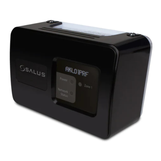
Device Installation Section 3 AKL01PRF Zone Pump Wiring Center Installation The AKL01PRF 1-Zone Pump Wiring Center pairs with an AWRT10RF Wireless Thermostat via the SG888ZB Gateway or AC10RF Coordinator to provide a heat demand signal to the boiler and control a zone pump . The AKL01PRF Single Zone Pump Wiring Center must be installed by a qualified contractor. -
Page 15: Akl04/06Prf Zone Pump Wiring Center Installation
Device Installation Section 3 AKL04/06PRF Zone Pump Wiring Center Installation The AKL04/06PRF Zone Pump Wiring Center pairs with an AWRT10RF Wireless Thermostat via the SG888ZB Gateway or AC10RF Coordinator to provide a heat demand signal to the boiler and control a zone pump . They can control up to 6 pumps with outputs for multiple heat demands . The AKL04/06PRF Zone Pump Wiring Center must be installed by a qualified contractor. - Page 16 11 . Terminals “XX” are closed any time there is a thermostat call to the wiring center . These may be wired directly to the thermostat connection on the boiler “TT” . Note, that if an AX10RF Receiver (sold separately) is used and configured as RX1, the “XX” terminals aren’t used .
-
Page 17: Akl08Rf Zone Valve Wiring Center Installation
Section 3 AKL08RF Zone Valve Wiring Center Installation The SALUS AKL08RF Zone Valve Wiring Center connects with AWRT10RF Wireless Thermostats via the AC10RF Coordinator or SG888ZB Gateway to control up to 32 actuators in 8 zones . It also provides power switching to a system circulator and a wired output for heat demand to a boiler . - Page 18 Device Installation Section 3 The boiler can be controlled wirelessly by the AKL08RF Zone Valve Wiring Center if an AX10RF Receiver, configured as RX1 (sold separately) is used with the system. However, if desired, the boiler’s thermostat input terminals (TT or RT) can be wired directly to terminals labeled “3” & “4”...
-
Page 19: Ax10Rf Receiver Installation
Section 3 AX10RF Receiver Installation The AX10RF Receiver can be configured as a system remote boiler switch (RX1) or a single channel output to a thermal actuator or zone valve . The AX10RF Receiver must be installed by a qualified contractor. Installation and repairs are to be performed according to all national and local codes required by the authority having jurisdiction. -
Page 20: Arv10Rfm Radiator Valve Actuator Installation
ARV10RFM Radiator Valve Actuator Installation The ARV10RFM-3 Radiator Valve Actuator attaches to a Thermostatic Radiator Valve (TRV) that can connect wirelessly with your SALUS system to control room temperature . 1 . Carefully read these instructions and all instructions supplied with the unit before starting the installation . -
Page 21: Awrt10Rf Pairing With Internet Connection (Sg888Zb Gateway)
• The Network Status LED on the AKL Relay Controller should be flashing • If an AX10RF Receiver is used, the LED backlight on the Auto/Manual switch of this device should be flashing red and the switch should be in the Auto position The display will show JOINING- - - with a 10 minute Step 1. - Page 22 • The Network Status Indicator on the AWRT10RF Thermostat will turn steady on, • T he Network Status LED on the AKL Series Relay Controller will turn steady on, and • I f present, the red LED backlight on the Auto/Manual switch of the AX10RF Receiver will turn steady on...
- Page 23 . ” Pressing the icon on the AWRT10RF Thermostat prior to pressing Finish on the SALUS Smart Home application starts the thermostat parameter setup. As covered in Section 8 of this manual, this can be setup after completing the pairing process.
- Page 24 AWRT10RF Pairing with Section 4 Internet Connection (SG888ZB Gateway) Once the AWRT10RF Thermostat has joined the network, SCANNING- - - is displayed with a 10-minute countdown timer showing the time allowed to find all the relay controllers on the network When the AWRT10RF Thermostat has Step 8.
-
Page 25: Pairing With Arv10Rfm Or Ava10M30Rf Radiator Valve Actuators
• The LED on the ARV/AVA Valve Actuator(s) should be off with NO MOTOR ACTIVITY, • If an AX10RF Receiver is used, the LED backlight on the Auto/Manual switch of this device should be flashing red with the switch in the Auto position . - Page 26 AWRT10RF Pairing with Section 4 Internet Connection (SG888ZB Gateway) 10 seconds The LED indicator will flash red. Step 3. Press and hold the pair button for 10 seconds to enter pairing mode on each actuator to be connected . Step 4. Use the JOINING- - - is displayed with a 10 minute keys on the countdown timer to show the remaining...
- Page 27 LED is solid red. Auto Manual In parameter setup mode, If an AX10RF Receiver configured as RX1 has joined the the AWRT10RF Thermostat network, it will automatically be paired with the AWRT and the starts with P 01 (displayed LED backlight on the Auto/Manual switch will stay solid red.
- Page 28 Step 7. Press “Finish” to complete the Step 8. Press the key to exit parameter setup and connection to the SALUS Smart Home go to the Home Screen . The display shows the current application . date & time, target temperature, relative humidity, network/internet status and room temperature .
-
Page 29: Pairing With Ax10Rf Receiver For Boiler Switching (Rx1)
For systems with multiple zones, a zone relay controller such as the SALUS AKL Series is recommended. Before starting the pairing process, be sure that the AX10RF Receiver is installed as shown in the installation instructions included with the device . - Page 30 AWRT10RF Pairing with Section 4 Internet Connection (SG888ZB Gateway) Step 2. Open the SALUS Smart Home mobile application and select the drop-down menu from the upper right side of the screen: Equipment Add New Equipment Scan for Equipment ...
- Page 31 Step 6. After naming the devices, If you do not rename the AWRT10RF Thermostat in the the application will show that set SALUS Smart Home application, the device may stay in up is complete . Press Finish to parameter setup mode. Press the key to exit setup.
-
Page 32: Pairing With Ax10Rf Receiver For Zone Valve Switching (Rx2)
• This pairing procedure is only used when direct control of an AX10RF Receiver by the AWRT10RF Thermostat is desired. • Each system will support only one AX10RF configured as RX1 and one configured as RX2. These two configurations can be used together to provide boiler switching and zone valve operation. - Page 33 The home screen will show for 3 seconds, then the Cn (Connected) indicates PAIRING- - - with a 10-Minute device will enter the that the AX10RF Receiver is countdown timer as the parameter setup mode . paired and connected . AWRT10RF Thermostat looks for an RX2 device .
- Page 34 Step 6. After naming the devices, If you do not rename the AWRT10RF Thermostat in the the application will show that set SALUS Smart Home application, the device may stay in up is complete . Press Finish to parameter setup mode. Press the key to exit setup.
-
Page 35: Salus Smart Home Application - Awrt10Rf Thermostat
SALUS Smart Home Application – Section 5 AWRT10RF Thermostat SALUS Smart Home Application: The following illustrates the home screen of the SALUS Smart Home Application on a mobile device or computer . Menu Choose Status Choose Thermostat Close Thermostat Thermostat Options... -
Page 36: Parameter Settings
SALUS Smart Home Application – Section 5 AWRT10RF Thermostat Parameter Settings Step 2. Parameters listed Step 3. After Step 1. Choose the can be changed without a making parameter icon to access parameter password . Enter “49” in the adjustments, press settings . -
Page 37: Remote Operation
SALUS Smart Home Application – Section 5 AWRT10RF Thermostat Remote Operation The following instructions describe operation of the AWRT10RF Thermostat using the SALUS Smart Home Application to make adjustments from any location . To make changes to the To change the current... - Page 38 SALUS Smart Home Application – Section 5 AWRT10RF Thermostat The following instructions describe identification and/or disabling of ARV/AVA Radiator Valve Actuators . It is not recommended to disable or enable radiator valve actuators without visual access to the devices .
-
Page 39: Awrt10Rf Pairing Without Internet Connection (Ac10Rf Coordinator)
. • The Network Status LED on the AKL Relay controller should be flashing and, • if an AX10RF Receiver is used, the LED backlight on the Auto/Manual switch of this device should be flashing red . - Page 40 AWRT10RF Pairing without Internet Section 6 Connection (AC10RF Coordinator) AKL Relay AKL01 Relay Controller ID# AKL01/04/06PRF Relay Controller Pairing Button Controller ID Zone LED Pulse Code Zone Zone Zone Zone LED Pattern ID # ID # Short = , Long = AKL08RF Relay Controller Pairing Button Step 2.
- Page 41 AWRT10RF Pairing without Internet Section 6 Connection (AC10RF Coordinator) Once the AWRT10RF Thermostat has joined the network, SCANNING- - - is displayed with a 10-minute countdown timer showing the time allowed to find all the relay controllers on the network When the AWRT10RF Thermostat has Step 4.
-
Page 42: Pairing With Arv10Rfm Or Ava10M30Rf Radiator Valve Actuators
• The LED indicator on the ARV/AVA Radiator Valve Actuator(s) should be off with NO MOTOR ACTIVITY . • If and AX10RF Receiver is used, the LED backlight on the Auto/Manual switch of this device should be flashing red and the switch should be in the AUTO position Step 1. - Page 43 AWRT10RF Pairing without Internet Section 6 Connection (AC10RF Coordinator) JOINING- - - is displayed with a 10 minute countdown Step 3. Use the timer to show the remaining time available to keys on the AWRT10RF complete the next steps . The icon will flash at the Thermostat to switch from bottom of the screen indicating that the thermostat is...
- Page 44 AWRT10RF Pairing without Internet Section 6 Connection (AC10RF Coordinator) Step 5. Press & hold After 3 seconds, the Step 4. Press the the flashing red pairing AWRT10RF Thermostat will to exit parameter setup enter the parameter setup button on the AC10RF and go to the home mode, starting with P 01 Coordinator for 5...
-
Page 45: Pairing With Ax10Rf Receiver For Boiler Switching (Rx1)
For systems with multiple zones, a zone relay controller such as the SALUS AKL Series is recommended. Before starting the pairing process, be sure that the AX10RF Receiver is installed as shown in the installation instructions included with the device . - Page 46 . Thermostat enters the mode . Cn (Connected) parameters set up mode . indicates that the AX10RF Receiver is paired and connected . Auto Manual Step 3. Press the key to exit setup and start normal operation . The AWRT10RF Thermostat display will show the current room temperature, target temperature, relative humidity along with indicators for the temperature mode and network status .
-
Page 47: Pairing With Ax10Rf Receiver For Zone Valve Switching (Rx2)
Connection (AC10RF Coordinator) Pairing with AX10RF Receiver for Zone Valve Switching (RX2) Each system will support only one AX10RF configured as RX1 and one configured as RX2. These two configurations can be used together to provide boiler switching and zone valve operation. - Page 48 . Thermostat enters the mode . Cn (Connected) parameters set up mode . indicates that the AX10RF Receiver is paired and connected . Auto Manual Step 3. Press the key to exit setup and start normal operation . The AWRT10RF Thermostat display will show the current date &...
-
Page 49: Resetting Factory Defaults
SALUS wireless systems can be reset to factory defaults. Resetting the SG888ZB Gateway with Internet Connection 1 . Open the SALUS Smart Home mobile application and select the drop down menu from the upper right side of the screen . -
Page 50: Resetting The Sg888Zb Gateway Without Internet Connection
Resetting Factory Defaults Section 7 Resetting the SG888ZB Gateway without Internet Connection To reset the SG888ZB Gateway to factory defaults without an internet connection: 1 . Press and hold the multi button on top of the SG888ZB Gateway . 2 . When the LED flashes red, release the multi button . After approximately 10 seconds, the LED ring turns solid red indicating the default values are loaded . -
Page 51: Resetting The Awrt10Rf Wireless Radiant Thermostat
Resetting Factory Defaults Section 7 Resetting the AWRT10RF Wireless Radiant Thermostat Before starting the reset procedure, press any key to light the display and prepare the thermostat for input . Step 3. Use the Step 2. Use the Step 1. Press the key to key to scroll to function 86 . -
Page 52: Resetting The Akl01/04/06Prf Zone Pump Or Akl08Rf Zone Valve Wiring Center
The AKL Wiring Center WILL NOT OPERATE correctly until the power is cycled off and on. with Internet Connection To reset the AKL Wiring Centers, delete them from the SALUS Smart Home mobile application as follows: 1 . Select the menu from the 2 . -
Page 53: Resetting The Ax10Rf Receiver
2 . Using the same probe, press and hold the left reset button until the red auto/manual backlight LED and the green on/off backlight LED flash alternately . 3 . To complete the reset, cycle the power to the AX10RF Receiver off for 10 seconds . with Internet Connection... -
Page 54: Resetting The Arv10Rfm Radiator Valve Actuator
Resetting Factory Defaults Section 7 Resetting the ARV10RFM Radiator Valve Actuator without Internet Connection 1 . Press and hold all three buttons on the ARV10RFM Valve Actuator for 30 seconds . The light will flash amber . 2 . Open the battery compartment and remove one of the batteries . 3 . -
Page 55: Awrt10Rf Thermostat Settings & Parameters
AWRT10RF Thermostat Settings & Parameters Parameter & Settings Adjustments using the Display & Keypad Installers can access parameters on the AWRT10RF using the SALUS Smart Home application if an SG888ZB Gateway is used and connected to the internet . Alternatively, the parameters may be entered directly through the display and keypad on the AWRT10RF Thermostat . - Page 56 Section 8 AWRT10RF Thermostat Settings & Parameters AWRT10RF Wireless Radiant Thermostat Settings Setting # Description Options Notes °F Degrees Fahrenheit S 01 Temperature Units °C Degrees Celsius 12-hour Example- 9:45 pm S 03 Clock Format 24-hour Example:- 21:45 Automatic Daylight Savings Time Enable S 04 Daylight Savings Time Automatic Daylight Savings Time Disable...
- Page 57 RDTR_VLV ARV/AVA Valve Actuators: Displays total # of paired valves Pair Device RLAY_CTL RCV1 AX10RF Receiver (RX1): Cn = Connected RCV2 AX10RF Receiver (RX2): Cn = Connected N (inactive) Settings S 03 through S 10 are not available Internal Schedule...
- Page 58 P01 = RDTR VLV . When KYS+APP is selected, parameter P26 (Lock Setpoint) can be activated from either the display and keypad of the AWRT10RF Thermostat by using the SALUS Smart Home application . If APP Key Lock Source KYS+APP is chosen, parameter P26 is only available online via the mobile application .
-
Page 59: Schedule Setup Using Display & Keypad
Section 8 AWRT10RF Thermostat Settings & Parameters Schedule Setup using Display & Keypad The AWRT10RF Wireless Radiant Thermostat is supplied as a non-programmable thermostat as default. Change P02 above to Y for programmable thermostat functionality. Step 1. Press the key to enter settings menu . Available settings are shown on the Settings Chart . Use the keys to scroll through available settings . - Page 60 Section 8 AWRT10RF Thermostat Settings & Parameters Step 5. Use the Step 6. Use the Step 7. Use the keys to change the hour to keys to change the minute keys to change the begin the first period . Press to begin the first period .
-
Page 61: Awrt10Rf Wireless Radiant Thermostat Operation
AWRT10RF Wireless Radiant Section 9 Thermostat Operation Setting the HVAC Mode using the Display & Keypad Step 1. Press any key on the Step 2. Press SELECT to The new mode setting keypad to activate the backlit will flash and the current accept the new heat mode . -
Page 62: Overriding Scheduled Temperature Using The Display & Keypad
AWRT10RF Wireless Radiant Section 9 Thermostat Operation Overriding Scheduled Temperature using the Display & Keypad If the setpoint is changed If the temperature Pressing SELECT while the while a schedule is running, change results in a heat target setpoint is flashing the AWRT10RF display will demand, the text above will toggle “PERMANENT... -
Page 63: Awrt10Rf Wireless Radiant Thermostat - Troubleshooting
Reset ARV/AVA Actuators and AWRT10RF Thermostat . ER:LLNK VA # # indicates total number of valves Repeat pairing procedure . Reset AX10RF Receiver and AWRT10RF Thermostat . ER:LLNK RCV1 Lost Link with Receiver: Configured as RX1 Repeat pairing procedure . -
Page 64: Reading Multiple Error Messages
SALUS AWRT10RF Wireless Radiant Thermostat Installation & Operation Instruction Manual AWRT10RF Wireless Radiant Thermostat - Section 10 Troubleshooting Reading Multiple Error Messages If there is more than one error, the AWRT10RF Thermostat will show the number of errors on the text message line alternating with the standard display . - Page 65 Appendix A A .1...
- Page 66 Appendix A A .2...
- Page 67 Appendix A A .3...
- Page 68 Appendix A A .4...
- Page 69 Appendix A A .5...