
Related Manuals for Salus ST100ZB


Summary of Contents for Salus ST100ZB
- Page 1 Connected Wireless System Guide Module 5 – Connected Fan Coil Controls SMC-GM-CWSG-M5-2019.11v1_2019-11-24...
-
Page 2: Table Of Contents
Display . . . . . . . . . . . . . . . . . . . . . . . . . . . . . . . . . . . . . . . . . . . . . . . . . . . . . . . . . . . . . . . . . . . . . . . . . . . . . . . . . . . . . . . . . . . . . . . . . . . . . . . . . . . . .2-1 ST100ZB Line Power Fan Coil Thermostat Included Parts / Tools Required . - Page 3 This page intentionally left blank.
-
Page 4: Introduction
Wireless System Guide has been divided into 5 Modules . Module 1 is required for all connected systems since it covers installation of the SG888ZB Gateway and the SALUS Smart Home application . The remaining modules are specific to a particular group of controls . -
Page 5: System Overview
By connecting the SG888ZB Gateway to your home network, the system is connected to the worldwide web . Monitor or adjust your Fan Coil system from anywhere via the SALUS Smart Home application from a smart device or computer . If the connection to the internet is lost, the system continues to function... -
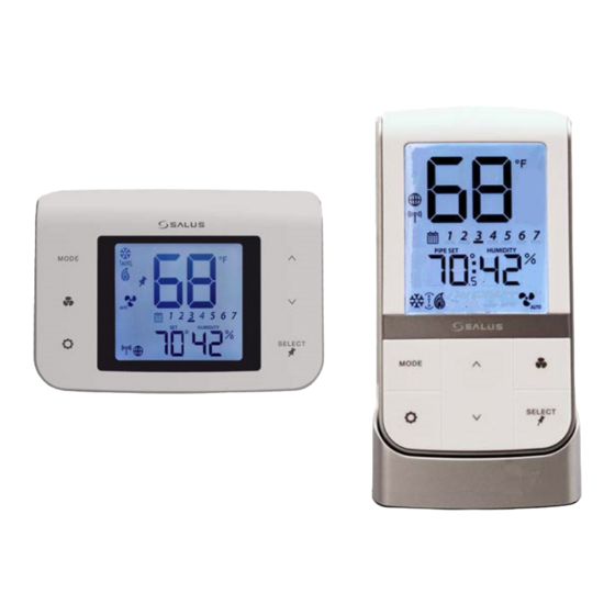
Page 6: Keypad & Display - Fan Coil Controls
Module 5 – Connected Fan Coil Controls Section 2 Keypad & Display – Fan Coil Controls Keypad Table 2.1: Keypad Functions MODE Heat, Cool, Auto, Off selection Increase Value Fan On/Auto, Low Speed, Medium Decrease Value Speed, or High Speed SELECT Confirm/Change Display Mode/Acti- Enter/Exit Settings mode... - Page 7 Fixed Fan Speed – Medium Fixed Fan Speed – High Wireless/Internet Indications Device connected to local network Device connected to SALUS Smart Home Service Test/Key Lock/Battery/Filter Test Mode (Special Code 22) Keys Locked Mode Battery Low (ST103 Wireless Remote Only)
-
Page 8: St100Zb Line Power Fan Coil Thermostat
Module 5 – Connected Fan Coil Controls Section 3 ST100ZB Line Power Fan Coil Thermostat Included Parts Be sure that all parts listed are included and available before starting installation . Mounting Screws Thermostat with Installation/Quick Start Wiring Labels Guide (English & French) -
Page 9: Remove Thermostat (If Replacing Existing Thermostat)
Module 5 – Connected Fan Coil Controls Section 3 ST100ZB Line Power Fan Coil Thermostat Remove Thermostat (if replacing existing thermostat) Before removing the existing thermostat, turn off power to the fan coil system . Step 1. Review and record the existing thermostat wiring configuraiton:... -
Page 10: Thermostat Installation
. Step 2. Connect the wiring to the ST100ZB Back Plate . Use the chart below to identify the desired configuration . Schematic diagrams for 4-Pipe, 2-Pipe and 2-Pipe Applications are provided on the following page . - Page 11 Module 5 – Connected Fan Coil Controls Section 3 ST100ZB Line Power Fan Coil Thermostat ST100ZB ST100ZB 2-Pipe Application 4-Pipe Application ST100ZB 2-Pipe Auxiliary Heat Application ST100ZB Internal Block Diagram...
- Page 12 Module 5 – Connected Fan Coil Controls Section 3 ST100ZB Line Power Fan Coil Thermostat Remove any unused, pre-wired leads or add wire nut cap to isolate line voltage . Step 3. Attach Thermostat to the Wiring Mount Step 4. Turn on power to the fan coil system by aligning the connector pins .
-
Page 13: St101Zb Low Voltage Fan Coil Thermostat
Module 5 – Connected Fan Coil Controls Section 4 ST101ZB Low Voltage Fan Coil Thermostat Included Parts Be sure that all parts listed are included and available before starting installation . Mounting Screws Installation/Quick Start Thermostat with Wiring Labels Guide (English & French) Wiring Mount Tools Required #1 Phillips or flathead screwdriver... -
Page 14: Remove Thermostat (If Replacing Existing Thermostat)
Module 5 – Connected Fan Coil Controls Section 4 ST101ZB Low Voltage Fan Coil Thermostat Remove Thermostat (if replacing existing thermostat) Before removing the existing thermostat, turn off power to the fan coil system . Step 1. Review and record the existing thermostat wiring configuraiton: Remove thermostat from wall plate to expose wiring terminals Take a photograph or note the wire colors and connections (see wiring reference table below) Attach wire labels to each of the wires... -
Page 15: Thermostat Installation
Module 5 – Connected Fan Coil Controls Section 4 ST101ZB Low Voltage Fan Coil Thermostat Thermostat Installation No Box or Horizontal Vertical 2” x 4” Junction Box 4” x 4” Junction Box 2” x 4” Junction Box (wall plate sold separately) (wall plate sold separately) Step 1. - Page 16 Module 5 – Connected Fan Coil Controls Section 4 ST101ZB Low Voltage Fan Coil Thermostat ST101ZB ST101ZB 2-Pipe Application 4-Pipe Application ST101ZB 2-Pipe Auxiliary Heat Application ST101ZB Internal Block Diagram...
- Page 17 Module 5 – Connected Fan Coil Controls Section 4 ST101ZB Low Voltage Fan Coil Thermostat Step 3. Attach Thermostat to the Wiring Mount Step 4. Turn on power to the fan coil system by aligning the connector pins . and thermostat . Make sure the connector pins are not bent and that the Thermostat is fully seated on the wiring mount .
-
Page 18: Sc102Zb Wireless Fan Coil Controller / St103Zb Wireless Fan Coil Remote
Module 5 – Connected Fan Coil Controls Section 5 SC102ZB Wireless Fan Coil Controller / ST103ZB Wireless Fan Coil Remot Included Parts Be sure that all parts listed are included and available before starting installation . Mounting Installation/Quick Start SC102ZB Wireless Fan Coil Wiring Labels Controller with Wiring Mount Screws... -
Page 19: Remove Thermostat (If Replacing Existing Thermostat)
Module 5 – Connected Fan Coil Controls Section 5 SC102ZB Wireless Fan Coil Controller / ST103ZB Wireless Fan Coil Remot Remove Thermostat (if replacing existing thermostat) Before removing the existing thermostat, turn off power to the fan coil system . Step 1. -
Page 20: Sc102Zb Fan Coil Controller Installation
Module 5 – Connected Fan Coil Controls Section 5 SC102ZB Wireless Fan Coil Controller / ST103ZB Wireless Fan Coil Remot SC102ZB Fan Coil Controller Installation No Box or Horizontal Vertical 2” x 4” Junction Box 4” x 4” Junction Box 2”... - Page 21 Module 5 – Connected Fan Coil Controls Section 5 SC102ZB Wireless Fan Coil Controller / ST103ZB Wireless Fan Coil Remot SC102ZB SC102ZB 2-Pipe Application 4-Pipe Application SC102ZB 2-Pipe Auxiliary Heat Application SC102ZB Internal Block Diagram...
-
Page 22: Optional External Antenna (Sold Separately)
Module 5 – Connected Fan Coil Controls Section 5 SC102ZB Wireless Fan Coil Controller / ST103ZB Wireless Fan Coil Remot Step 3. Attach Thermostat to the Wiring Mount Step 4. Turn on power to the fan coil system by aligning the connector pins . and thermostat . -
Page 23: St103Zb Wireless Fan Coil Remote Installation
Module 5 – Connected Fan Coil Controls Section 5 SC102ZB Wireless Fan Coil Controller / ST103ZB Wireless Fan Coil Remot ST103ZB Wireless Fan Coil Remote Installation The ST103ZB Wireless Fan Coil Remote acts as a remote thermostat which can be wall mounted or placed in a stand for desk or cabinet top operation . -
Page 24: Pairing Instructions - Fan Coil Controls
. described previously will be displayed . Joining the SG888ZB Gateway Network Step 1. Open the SALUS Smart Home application, select the drop-down menu from the upper right of the screen and select: All Devices Add new device . - Page 25 Section 6 Pairing Instructions – Fan Coil Controls Step 2. Click “Scan Devices” Step 3. Choose the check box The SALUS Smart Home application scans for devices that corresponds to the device as displayed . to connect . Note that multiple devices can be connected at the same time .
-
Page 26: Linking Sc102Zb Fan Coil Controller To St103Zb Remote
Section 6 Pairing Instructions – Fan Coil Controls Step 7. Press Finish to complete connection . The devices will appear on the SALUS Smart Home dashboard when the connection is complete . Linking SC102ZB Fan Coil Controller to ST103ZB Remote Step 8. -
Page 27: Configuring Fan Coil Controls With Salus Smart Home Application
Module 5 – Connected Fan Coil Controls Section 6 Pairing Instructions – Fan Coil Controls Configuring Fan Coil Controls with SALUS Smart Home Application To change configuration Detailed descriptions of For more configuration settings, settings, choose the setup these setting can be found enter 49 for the device password icon from the SC102ZB menu . -
Page 28: Device Configuration - Fan Coil Controls
Module 5 – Connected Fan Coil Controls Section 7 Device Configuration – Fan Coil Controls Settings Button Operation Press to adjust the settings in Table 7 .1 . Some of these settings are not accessible depending on the parameter configuration listed in Appendix A . Press select to choose the current value and move to the next available setting . Press to exit the settings menu . - Page 29 Note: This setting is available in standalone or local mode only. Note: Schedule parameters are only available in standalone or local mode . If the Fan Coil Thermostat is connected to the SALUS Smart Home application, the schedule must be programmed on your PC or smart device .
- Page 30 Module 5 – Connected Fan Coil Controls Section 7 Device Configuration – Fan Coil Controls Schedule (Continued) Time Interval: Use the keys to set the start time for each time interval, displayed next to the calendar icon . 1st: Set the hour for the time interval start 2nd: Set the minutes for time interval start Press SELECT to move on to the heating setpoint .
-
Page 31: Special Function Codes
Module 5 – Connected Fan Coil Controls Section 7 Device Configuration – Fan Coil Controls Special Function Codes MODE, To access special functions, press and hold the keys simultaneously . Use the keys to scroll through the available codes . SELECT Identify Mode –... - Page 32 Module 5 – Connected Fan Coil Controls Section 7 Device Configuration – Fan Coil Controls SELECT Join/Leave Network – Press to join or leave a network . If the thermostat has not joined a network, the display will enter the pairing sequence . Follow the steps under Pairing in Section 3 .
-
Page 33: Operation
Gateway RF Icon None None (Flashing) Display SALUS Smart Home None None None None Icon Device or SALUS SetPoint Device Only Device Only Smart Home Change Available application In Device, In SALUS Smart Schedule In Device, if enabled Available if enabled... -
Page 34: Programmable Thermostat (Standalone Or Local Mode Only)
Module 5 – Connected Fan Coil Controls Section 8 Operation Programmable Thermostat (Standalone or Local Mode Only) When in Standalone or Local mode, the default operation of the Fan Coil Thermostat is as a Non- Programmable Thermostat with no scheduling capability . Changing the value of Parameter P00 (See Appendix A) to 1, changes the device to Programmable, allowing users to program a wide variety of schedule options . -
Page 35: Fan Modes
Module 5 – Connected Fan Coil Controls Section 8 Operation Fan Modes Fan Mode Speed Display Output Terminal Fan output is only activated when a thermostat call is present (On Call Fan) . When a call is present the fan runs at the selected speed . High Medium Fan output is only activated when a thermostat call is present (On Call Fan) . -
Page 36: Accessory Function
Module 5 – Connected Fan Coil Controls Section 8 Operation Accessory Function Terminals Ac1 and Ac2 on the Fan Coil Thermostat provide output to an accessory such as a Humidifier, Dehumidifier, Heat Recovery Ventilator (HRV) or Energy Recovery Ventilator (ERV) . The built-in humidity monitor continually samples humidity at the thermostat and will operate a humidifier or dehumidifier to maintain the specified value . -
Page 37: Away Mode
Module 5 – Connected Fan Coil Controls Section 8 Operation AWAY Mode Fan Coil Thermostat terminals Ts and Tc are used to initiate or terminate an Away state in the device . The Ts/Tc contact closure is configured by P16 as a Normally Open or Normally Closed contact, or as an input to be ignored . -
Page 38: Device Troubleshooting
Module 5 – Connected Fan Coil Controls Section 9 Device Troubleshooting Troubleshooting The following error messages are displayed to identify issues when certain conditions occur . Table 9.1: Error Messages Error Message Description Corrective Action Error 01: Pipe supply sensor circuit is •... -
Page 39: Parameter List
Module 5 – Connected Fan Coil Controls Appendix A Parameter List To change parameters, press and hold the MODE, keys simultaneously . Use the keys to scroll to “49” and press SELECT . Name Values Default Description/Comment 0 = Non-Programmable Type of thermostat 1 = Programmable 0 = 2 Pipe... - Page 40 Module 5 – Connected Fan Coil Controls Appendix A Parameter List Name Values Default Description/Comment Offset of external ±6°F - 1°F increments 0°F sensor (±3°C - 0 .5°C increments (0°C) Standalone mode: P12 = 0 0 = External sensor External sensor 1 = Zigbee remote sensor to EXT with 0 = Analog input...
- Page 41 Module 5 – Connected Fan Coil Controls Appendix A Parameter List Name Values Default Description/Comment Display only if P23=1, device Set span for cooling 0 .5° to 2°F increment 0 .5°F 0 .5°F only display 0 .2/0 .5/0 .7/1 .0°C or using span control (0 .25°...