Table of Contents
Advertisement
Advertisement
Table of Contents

Related Manuals for Panasonic KX-TS550MEB


Summary of Contents for Panasonic KX-TS550MEB
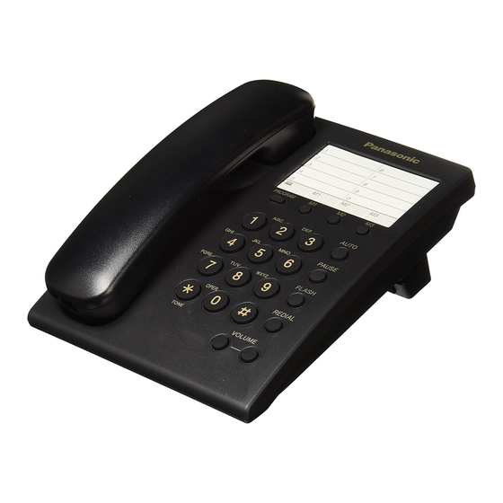
- Page 1 ORDER NO. KM40706334CE Telephone Equipment KX-TS550MEB KX-TS550MEW Integrated Telephone System Black Version White Version (for Mexico) © 2007 Panasonic Communications Co., Ltd. All rights reserved. Unauthorized copying distribution is a violation of law.
-
Page 2: Table Of Contents
KX-TS550MEB / KX-TS550MEW Note for TABLE OF CONTENTS: Because sections 5, 6 and 7 of this manual are extracts from the operating instructions for this model, they are subject to change without notice. You can download and refer to the original operating instructions on TSN Server for further information. -
Page 3: About Lead Free Solder (Pbf: Pb Free)
KX-TS550MEB / KX-TS550MEW 1 ABOUT LEAD FREE SOLDER (PbF: Pb free) Note: Caution • PbF solder has a melting point that is 50°F ~ 70° F In the information below, Pb, the symbol for lead in the (30°C ~ 40°C) higher than Pb solder. Please use a... -
Page 4: For Service Technicians
KX-TS550MEB / KX-TS550MEW 2 FOR SERVICE TECHNICIANS • Repair service shall be provided in accordance with repair technology information such as service manual so as to prevent fires, injury or electric shock, which can be caused by improper repair work. -
Page 5: Location Of Controls
KX-TS550MEB / KX-TS550MEW 4 LOCATION OF CONTROLS... -
Page 6: Settings
KX-TS550MEB / KX-TS550MEW 5 SETTINGS 5.1. Connection... -
Page 7: Operations
KX-TS550MEB / KX-TS550MEW 6 OPERATIONS 6.1. Making Calls 6.2. Answering Calls 7 SPECIAL FEATURES 7.1. For Call Waiting Service Users 7.2. Temporary Tone Dialing (For Rotary or Pulse Service Users) -
Page 8: Disassembly Instructions
KX-TS550MEB / KX-TS550MEW 8 DISASSEMBLY INSTRUCTIONS Shown in Fig —. To remove —. Remove —. Lower Cabinet Screws (2.6 × 10) ... . . (A) × 5 P.C. Boards Remove the P.C.Boards... -
Page 9: Trouble Shooting Guide
KX-TS550MEB / KX-TS550MEW 9 TROUBLE SHOOTING GUIDE 9.1. Service Hints SYMPTOM CURE No Tone Dialing Check IC1, Q2, Q1, C22 and VR1. Dead Check IC1, Q2, Q1 and D17. Rings, no dial tone, no pulse or tone dial Check Q1, Q2, Q7, D17 and Q3. -
Page 10: Problems With The Handset
KX-TS550MEB / KX-TS550MEW 9.3. Problems With the Handset 9.4. Tone Dialing Problems... -
Page 11: Problems With Ringer
KX-TS550MEB / KX-TS550MEW 9.5. Problems With Ringer... -
Page 12: How To Check The Ic1 (Scanning To The Key)
KX-TS550MEB / KX-TS550MEW 9.6. How to Check the IC1 (Scanning to the key) -
Page 13: 10 Block Diagram
KX-TS550MEB / KX-TS550MEW... -
Page 14: Option Jumper Table
KX-TS550MEB / KX-TS550MEW 11 OPTION JUMPER TABLE Note: Refer to Main (Flow Solder Side View) (P.30) -
Page 15: Circuit Operations
KX-TS550MEB / KX-TS550MEW 12 CIRCUIT OPERATIONS 12.1. Telephone Line Interface and Pulse Dial Circuit When the hook switch SW1 is ON (off-hook), the circuit is closed, and current is supplied to the base of Q2 via the diode bridge D17 and Q2 is On → Q1 is ON (OFF-HOOK condition). - Page 16 KX-TS550MEB / KX-TS550MEW...
-
Page 17: Power Circuit And Redial Back-Up Circuit
KX-TS550MEB / KX-TS550MEW 12.3. Power Circuit and Redial Back-up Circuit Function: This set is powered from the line. When it is an OFF-HOOK status, Tel Line → D17 → Q1 → R9 → Pin 27 of IC1 (to become the power supply for IC1 speech network). -
Page 18: 13 Cpu Data
KX-TS550MEB / KX-TS550MEW 13 CPU DATA LS 1 MFL 2 RO 3 STB 6 Clock frequency: 3.58MHz CI 7 Operating range: 13~100mA MO 8 LLC 9 HS/DP 10 OSC 11 MODE 12 C4 13 C3 14 C2 15 C1 16... - Page 19 KX-TS550MEB / KX-TS550MEW...
-
Page 20: Cabinet And Electrical Parts Location
KX-TS550MEB / KX-TS550MEW 14 CABINET AND ELECTRICAL PARTS LOCATION... -
Page 21: Accessory And Packing Materials
KX-TS550MEB / KX-TS550MEW 15 ACCESSORY AND PACKING MATERIALS... -
Page 22: Terminal Guide Of Ics Transistors And Diodes
KX-TS550MEB / KX-TS550MEW 16 TERMINAL GUIDE OF ICs TRANSISTORS AND DIODES... -
Page 23: Replacement Parts List
17.1.1. Cabinet and Electrical Parts ERJ3GEYJ392 3.9K ERJ3GEYJ220 Ref. Part No. Part Name & Description Remarks ERJ3GEYJ562 5.6K ERDS2TJ823 PQBH10035Z2 PUSH BUTTON (for KX-TS550MEB) ABS-HB ERJ3GEYJ105 PQBH10035Z1 PUSH BUTTON (for KX-TS550MEW) ABS-HB ERDS1TJ330 PQKM10615Z2 CABINET BODY (for PS-HB ERJ3GEYJ331 TS550MEB) -
Page 24: Accessories And Packing Materials
OperatingInstructions (Instruction book) on TSN Server. Ref. Part No. Part Name & Description Remarks PQJA10075Z CORD, TELEPHONE PQJA10153Y CORD, CURL (for KX-TS550MEB) PQJA10153Z CORD, CURL (for KX-TS550MEW) PQJXE0601Z HANDSET (for KX-TS550MEB) PQJXE0611Z HANDSET (for KX-TS550MEW) PQQX16332Z INSTRUCTION BOOK (*1) -
Page 25: For Schematic Diagram
KX-TS550MEB / KX-TS550MEW 18 FOR SCHEMATIC DIAGRAM 1. DC voltage measurements are taken with electronic voltmeter from negative terminal. 2. This schematic diagram may be modified at any time with the development of new technology. Important Safety Notice: Components identified by mark have special characteristics important for safety. -
Page 26: Schematic Diagram
KX-TS550MEB / KX-TS550MEW 19 SCHEMATIC DIAGRAM WBH201 WBH201 RING 3.9M POS1 500V680P 6.8M S1-2 0.01ZF 500V680P 250V1 Ringer High 50V 0.0068 Red+ R102 330 Black- R103 12K R104 RI _ RINGER CIRCUIT 100K 16V3. 3 C12 0.018 2.2K JACK3 (10) (11) C13 0.018... - Page 27 KX-TS550MEB / KX-TS550MEW FLT2 16V10 1 LS 2 MFL 3 R0 4 VDD 5 AGND 10uH FLT1 50V1 JP11 7 CI JP12 8 M0 JP13 0 VS.VSS 10 HS/DP 11 OSC 12 MODE 13 C4 14 C3 15 C2 16 C1...
-
Page 28: Memo
KX-TS550MEB / KX-TS550MEW 19.1. Memo... -
Page 29: Circuit Board
KX-TS550MEB / KX-TS550MEW 20 CIRCUIT BOARD 20.1. Main (Component View) KX-TS550 CIRCUIT BOARD (Main) Component View... -
Page 30: Main (Flow Solder Side View)
KX-TS550MEB / KX-TS550MEW 20.2. Main (Flow Solder Side View) JP19 JP18 JP17 JP14 JP23 JP15 JP16 JP24 JP20 JP21 JP22 JP25 JP26 JP28 R101 C103 R105 R102 R104 R103 RING KX-TS550 CIRCUIT BOARD (Main) Flow Solder Side View *: Refer to OPTION JUMPER TABLE (P.14) -
Page 31: Operation (Flow Solder Side View)
KX-TS550MEB / KX-TS550MEW 20.3. Operation (Flow Solder Side View) FLASH REDIAL KX-TS550 CIRCUIT BOARD (Operation) Flow Solder Side View KXTS550MEBAK KXTS550MEWAK...