Table of Contents
Advertisement
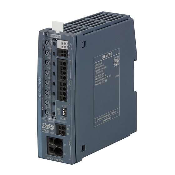
SITOP SEL1200-1400
SITOP power supply
SITOP SEL1200-1400
Manual
SITOP SEL1200 8 x 10 A
6EP4438-7FB00-3DX0
SITOP SEL1400 8 x 10 A
6EP4438-7EB00-3DX0
06.2019
A5E46496083-1-76
Overview
Safety instructions
Description, device design,
dimension drawing
Mounting/removal
Mounting position, mounting
clearances
Installation
Technical data
Safety, approvals, EMC
Ambient conditions
Environment
Service & Support
1
2
3
4
5
6
7
8
9
10
Advertisement
Table of Contents

Related Manuals for Siemens SITOP SEL1200


Summary of Contents for Siemens SITOP SEL1200
- Page 1 SITOP power supply Mounting/removal SITOP SEL1200-1400 Mounting position, mounting clearances Installation Manual Technical data Safety, approvals, EMC Ambient conditions Environment Service & Support SITOP SEL1200 8 x 10 A 6EP4438-7FB00-3DX0 SITOP SEL1400 8 x 10 A 6EP4438-7EB00-3DX0 06.2019 A5E46496083-1-76...
-
Page 2: Legal Information
Note the following: WARNING Siemens products may only be used for the applications described in the catalog and in the relevant technical documentation. If products and components from other manufacturers are used, these must be recommended or approved by Siemens. Proper transport, storage, installation, assembly, commissioning, operation and maintenance are required to ensure that the products operate safely and without any problems. -
Page 3: Overview
● Overcurrents are reliably switched off, independent of the cable length and cable cross- section ● The 24 V supply for the other loads is maintained ● 2 adjacent outputs can be connected in parallel to increase the power rating (for max. 15 A) SITOP SEL1200-1400 Manual, 06.2019, A5E46496083-1-76... - Page 4 Reference labeling plate (160 plates) 6ES7193-6LF30-0AW0 Validity This manual provides information on the following products: ● Selectivity module SITOP SEL1200 8 × 10 A Article number: 6EP4438-7FB00-3DX0 product state: 1 ● Selectivity module SITOP SEL1400 8 × 10 A Article number: 6EP4438-7EB00-3DX0...
-
Page 5: Table Of Contents
Connection at the output ......................35 Technical data ............................37 Input ............................37 Output ............................. 38 Efficiency ..........................40 Protection and monitoring ....................... 40 MTBF ............................40 Mechanical system ......................... 41 Accessories ..........................41 Dimension drawing ......................... 42 SITOP SEL1200-1400 Manual, 06.2019, A5E46496083-1-76... - Page 6 Table of contents Safety, approvals, EMC ........................... 43 Safety ............................. 43 Approvals ..........................44 EMC ............................45 Ambient conditions ..........................47 Environment ............................49 Service & Support ............................ 51 SITOP SEL1200-1400 Manual, 06.2019, A5E46496083-1-76...
-
Page 7: Safety Instructions
Before installation or maintenance work can begin, the system's main switch must be switched off and measures taken to prevent it being switched on again. If this instruction is not observed, touching live parts can result in death or serious injury. SITOP SEL1200-1400 Manual, 06.2019, A5E46496083-1-76... - Page 8 Safety instructions SITOP SEL1200-1400 Manual, 06.2019, A5E46496083-1-76...
-
Page 9: Description, Device Design, Dimension Drawing
(ON/OFF/RST) or remote reset (RST). The status of the output is displayed using a multi- color LED for each output. The status of the outputs can be processed via a group signaling contact (13, 14) or via a serial single-channel signal. SITOP SEL1200-1400 Manual, 06.2019, A5E46496083-1-76... - Page 10 (ON/OFF/RST) pushbutton and indicator light for each output ⑦ Selector switch for diagnostic interface (COM) ⑧ Selector switch for switch-in delay (time definition) (TD1, TD2) ⑨ Mounting rail slider ⑩ Natural convection ⑪ Clearance above/below Figure 2-1 Design SITOP SEL1200-1400 Manual, 06.2019, A5E46496083-1-76...
-
Page 11: Connections And Terminal Designation
Overload of the wiring The "0 V" connection is only used to supply the internal electronics of the selectivity module. The 0 V of the connected loads must be routed directly to the power supply using separate cables! SITOP SEL1200-1400 Manual, 06.2019, A5E46496083-1-76... -
Page 12: Potentiometer
When delivered, the maximum possible response threshold is set. Figure 2-3 Potentiometer Note It is only permissible to use an insulated screwdriver when actuating the potentiometer. For information on actuating the potentiometer (screwdriver, torque), see Figure 2-2 Terminal data (Page 11). SITOP SEL1200-1400 Manual, 06.2019, A5E46496083-1-76... -
Page 13: Status Displays And Signaling
The operating state of the outputs is displayed using multi-color LEDs at the front of the device. Symbols indicate the significance of each LED, which are listed in the following table. LED off LED is continuously lit LED flashes SITOP SEL1200-1400 Manual, 06.2019, A5E46496083-1-76... - Page 14 '1' = 24 V DC / '0' = 0 V (pull down) ④ If the selector switch for the diagnostics interface (COM) is at 0, then signal contact only closed if all channels are in the LED state "green", "green flashing" or "orange flashing". SITOP SEL1200-1400 Manual, 06.2019, A5E46496083-1-76...
- Page 15 Description, device design, dimension drawing 2.4 Status displays and signaling Additional information about the data transfer (COM = 1) is provided in the documents: ● Diagnostics interface (https://support.industry.siemens.com/cs/ww/en/view/109767425) ● Faceplates and communication blocks (https://support.industry.siemens.com/cs/ww/en/view/109763709) See also SITOP (http://www.siemens.com/sitop) Support (https://support.industry.siemens.com) SITOP SEL1200-1400 Manual, 06.2019, A5E46496083-1-76...
-
Page 16: Buttons And Selector Switches
Buttons and selector switches ⑥ Buttons (ON/OFF/RST) for the selectivity module SITOP SEL1200-1400 fulfill the following two functions: 1. manually switching an output off and on (see the following). 2. resetting an output automatically switched off due to an overload condition (see Chapter Electronic overload shutdown and reset (Page 18)). - Page 17 (RST) An output that has been manually switched off remains saved (latch) even when the supply voltage is no longer available, and is a manually switched off when the supply voltage returns. SITOP SEL1200-1400 Manual, 06.2019, A5E46496083-1-76...
-
Page 18: Electronic Overload Shutdown And Reset
● In the range 100 - 150 % of the selected current response threshold, an overload current is permissible for 5 seconds (LED of the output flashes green), then the output is electronically shut down (LED of the output is lit red). SITOP SEL1200-1400 Manual, 06.2019, A5E46496083-1-76... - Page 19 (LED of the output flashes red). ⑥ 2. Press the reset button of the particular output: Electronic shutdown was reset, and the output is switched-on again (LED of the output is lit green). SITOP SEL1200-1400 Manual, 06.2019, A5E46496083-1-76...
- Page 20 If, after a reset, the cause of the overload is still present, then the output is again automatically shut down. Before carrying out a reset, remove the cause of the overload to prevent a new shutdown. SITOP SEL1200-1400 Manual, 06.2019, A5E46496083-1-76...
-
Page 21: Setting The Switch-On Delay Time
200 ms delay between the outputs being switched on 500 ms delay between the outputs being switched on The next time that the selectivity module powers up, the outputs are sequentially switched on corresponding to the selected delay time. SITOP SEL1200-1400 Manual, 06.2019, A5E46496083-1-76... -
Page 22: Block Diagram
Description, device design, dimension drawing 2.8 Block diagram Block diagram Figure 2-9 Block diagram SITOP SEL1200-1400 Manual, 06.2019, A5E46496083-1-76... -
Page 23: Dimensions And Weight
2.9 Dimensions and weight Dimensions and weight Figure 2-10 Dimension drawings 6EP4438-7FB00-3DX0 6EP4438-7EB00-3DX0 Dimensions (W × H × D) in mm 45 × 135 × 125 45 × 135 × 125 Weight Approx. 0.30 kg Approx. 0.50 kg SITOP SEL1200-1400 Manual, 06.2019, A5E46496083-1-76... - Page 24 Description, device design, dimension drawing 2.9 Dimensions and weight SITOP SEL1200-1400 Manual, 06.2019, A5E46496083-1-76...
-
Page 25: Mounting/Removal
WARNING Installing the device in a housing or a control cabinet The SITOP SEL1200-1400 selectivity modules are built-in units. They must be installed in a housing or control cabinet where only qualified personnel have access. The device can be mounted in a control cabinet on standard mounting rails (see Chapter... - Page 26 Mounting/removal SITOP SEL1200-1400 Manual, 06.2019, A5E46496083-1-76...
-
Page 27: Mounting Position, Mounting Clearances
50 mm). No space is required at the side. Individual output current as a function of the ambient temperature and installation altitude Figure 4-1 6EP4438-7FB00-3DX0 standard mounting position Figure 4-2 6EP4438-7EB00-3DX0 standard mounting position SITOP SEL1200-1400 Manual, 06.2019, A5E46496083-1-76... - Page 28 Mounting position, mounting clearances 4.1 Standard mounting position Figure 4-3 Mounting height derating SITOP SEL1200-1400 Manual, 06.2019, A5E46496083-1-76...
-
Page 29: Other Mounting Positions
Particularly when installing on a vertically fastened standard mounting rail, additional measures may be required, e.g. to prevent the device from slipping on the standard mounting rail. 4.2.1 SEL1200 8 x 10 A 6EP4438-7FB00-3DX0 Figure 4-4 Mounting position 1 Figure 4-5 Mounting position 2 SITOP SEL1200-1400 Manual, 06.2019, A5E46496083-1-76... - Page 30 Mounting position, mounting clearances 4.2 Other mounting positions Figure 4-6 Mounting position 3 Figure 4-7 Mounting position 4 Figure 4-8 Mounting position 5 SITOP SEL1200-1400 Manual, 06.2019, A5E46496083-1-76...
-
Page 31: Sel1400 8 X 10 A 6Ep4438-7Eb00-3Dx0
Mounting position, mounting clearances 4.2 Other mounting positions 4.2.2 SEL1400 8 x 10 A 6EP4438-7EB00-3DX0 Figure 4-9 Mounting position 1 Figure 4-10 Mounting position 2 Figure 4-11 Mounting position 3 SITOP SEL1200-1400 Manual, 06.2019, A5E46496083-1-76... - Page 32 Mounting position, mounting clearances 4.2 Other mounting positions Figure 4-12 Mounting position 4 Figure 4-13 Mounting position 5 SITOP SEL1200-1400 Manual, 06.2019, A5E46496083-1-76...
-
Page 33: Installation
Only appropriately qualified personnel may work on or in the vicinity of this equipment. Perfect, safe, and reliable operation of this equipment is dependent on proper transportation, storage, installation and mounting. SITOP SEL1200-1400 Manual, 06.2019, A5E46496083-1-76... - Page 34 40 A or 60 A, then the maximum current should be reduced to 40 A or 60 A per branch by using additional feeder cables directly from the power supply to the selectivity modules connected in parallel. SITOP SEL1200-1400 Manual, 06.2019, A5E46496083-1-76...
-
Page 35: Connection At The Output
OUTPUT 1, 2, 3, 4, 5, 6, 7, 8. (terminal cross-sections, see Figure Terminal data (Page 11)). Note The 0 V of the loads must be routed directly to the power supply using separate cables! SITOP SEL1200-1400 Manual, 06.2019, A5E46496083-1-76... - Page 36 Installation 5.2 Connection at the output SITOP SEL1200-1400 Manual, 06.2019, A5E46496083-1-76...
-
Page 37: Technical Data
Input 6EP4438-7FB00-3DX0 6EP4438-7EB00-3DX0 Input Regulated DC voltage Rated voltage U 24 V in rated Voltage range 20.4 - 30 V Overvoltage strength 35 V Input current at U Max. 60 A in rated SITOP SEL1200-1400 Manual, 06.2019, A5E46496083-1-76... -
Page 38: Output
Shutdown characteristics: Figure 6-1 Shutdown characteristic The following applies for the SEL1200: In the range > 150 %, a higher current is briefly permitted; afterwards it is shut down corresponding to the "Shutdown characteristic" diagram. SITOP SEL1200-1400 Manual, 06.2019, A5E46496083-1-76... - Page 39 ● In the range 100 - 150 % of the selected current response threshold, an overload current is permissible for 5 seconds (LED of the output flashes green), then the output is electronically shut down (LED of the output is lit red). SITOP SEL1200-1400 Manual, 06.2019, A5E46496083-1-76...
-
Page 40: Efficiency
24 V AC/0.1 A; 30 V DC/0.1 A MTBF 6EP4438-7FB00-3DX0 6EP4438-7EB00-3DX0 Mean Time Between Failures > 500,000 hours at 40 °C, rated load, > 300,000 hours at 40 °C, rated load, 24 hour operation 24 hour operation SITOP SEL1200-1400 Manual, 06.2019, A5E46496083-1-76... -
Page 41: Mechanical System
45 mm Mounting height 225 mm Weight, approx. 0.30 kg 0.50 kg Mounting Can be snapped onto standard TH 35-15/7,5 mounting rails (EN 60715) Accessories 6EP4438-7FB00-3DX0 6EP4438-7EB00-3DX0 Mechanical accessories Reference labeling plate (160 plates) 6ES7193-6LF30-0AW0 SITOP SEL1200-1400 Manual, 06.2019, A5E46496083-1-76... -
Page 42: Dimension Drawing
Technical data 6.8 Dimension drawing Dimension drawing See Chapter Dimensions and weight (Page 23). CAD data that can be downloaded from the Internet: 6EP4438-7FB00-3DX0 (https://www.automation.siemens.com/bilddb/index.aspx?objkey=G_KT01_XX_01575&gridvi ew=view1¤tpage=1&pagesize=12&showdetail=False&view=Search) 6EP4438-7EB00-3DX0 (https://www.automation.siemens.com/bilddb/index.aspx?objkey=G_KT01_XX_01578&gridvi ew=view1¤tpage=1&pagesize=12&showdetail=False&view=Search) SITOP SEL1200-1400 Manual, 06.2019, A5E46496083-1-76... -
Page 43: Safety, Approvals, Emc
Safety, approvals, EMC Safety 6EP4438-7FB00-3DX0 6EP4438-7EB00-3DX0 Standard for safety acc. to EN 60079-0 and EN 60079-15 Protection class Class III Degree of protection (EN 60529) IP20 SITOP SEL1200-1400 Manual, 06.2019, A5E46496083-1-76... -
Page 44: Approvals
UR (UL 2367) file E328600; cULus (UL 508, CSA C22.2 No. 107.1) file E197259 cCSAus approval Available soon Explosion protection Available soon ATEX approval Available soon IECEx approval Available soon cULus HazLoc Available soon Marine approvals Available soon SITOP SEL1200-1400 Manual, 06.2019, A5E46496083-1-76... -
Page 45: Emc
0.5 kV symmetrical at the DC output High-frequency fields EN 61000-4-6 10 V; 0.15 - 80 MHz Magnetic fields EN 61000-4-8 30 A/m; 50 Hz Generic standards EN 61000-6-2 Noise immunity for industrial environments EN 61000-6-3 Emission for residential areas SITOP SEL1200-1400 Manual, 06.2019, A5E46496083-1-76... - Page 46 Safety, approvals, EMC 7.3 EMC SITOP SEL1200-1400 Manual, 06.2019, A5E46496083-1-76...
-
Page 47: Ambient Conditions
-7.5% / 1000 m or the ambient temperature must be reduced by 5 K / 1000 m (see Standard mounting position (Page 27)) Storage: 1080 - 660 hPa (0 - 3500 m) • SITOP SEL1200-1400 Manual, 06.2019, A5E46496083-1-76... - Page 48 Ambient conditions SITOP SEL1200-1400 Manual, 06.2019, A5E46496083-1-76...
-
Page 49: Environment
The devices are in conformance with RoHS. As a rule, only non-silicon precipitating materials are used. Disposal guidelines Packaging and packaging aids can and should always be recycled. The product itself may not be disposed of as domestic refuse. SITOP SEL1200-1400 Manual, 06.2019, A5E46496083-1-76... - Page 50 Environment SITOP SEL1200-1400 Manual, 06.2019, A5E46496083-1-76...
-
Page 51: Service & Support
The online catalog and the online ordering system are available through the Industry Mall homepage: Industry Mall (http://www.siemens.com/industrymall/de) Contact persons If you have any questions regarding the use of our products, then contact the Siemens contact person in your regional Siemens sales office. SITOP SEL1200-1400 Manual, 06.2019, A5E46496083-1-76... - Page 52 Service & Support You can find these addresses as follows: ● On the Internet (http://www.automation.siemens.com/partner) ● Industry Mall (http://www.siemens.com/industrymall/de) SITOP SEL1200-1400 Manual, 06.2019, A5E46496083-1-76...