
Related Manuals for Siemens Simatic 6DL2804-0 Series


Summary of Contents for Siemens Simatic 6DL2804-0 Series
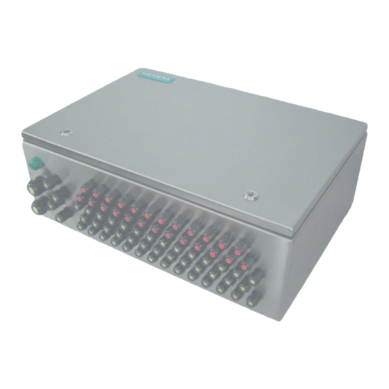
- Page 1 Wall-mount enclosure SIMATIC Distributed I/O Wall-mount enclosure 6DL2804-0xxxx 6DL2804-0xxxx Installation manual · Augst 2009 simatic...
- Page 3 Introduction Safety information Description SIMATIC Mounting Distributed I/O Wall-mount enclosure 6DL2804-0xxxx Maintenance and servicing Technical specifications Hardware Installation Manual Connection diagram Dimension drawing ESD Guidelines Service and support 08/2009 A5E00378691N-02...
-
Page 4: A5E00378691N
Note the following: WARNING Siemens products may only be used for the applications described in the catalog and in the relevant technical documentation. If products and components from other manufacturers are used, these must be recommended or approved by Siemens. Proper transport, storage, installation, assembly, commissioning, operation and maintenance are required to ensure that the products operate safely and without any problems. -
Page 5: Table Of Contents
Table of contents Introduction..............................7 Purpose of this documentation ......................7 History ............................7 Safety information............................9 General information ........................9 Laws and directives ........................9 Qualified personnel ........................9 Measures .............................10 Description............................... 11 Overview ............................11 Application............................11 Product features...........................12 Structure of the type designation ....................13 Details of the enclosure .......................14 Mounting.............................. - Page 6 Table of contents Wall-mount enclosure 6DL2804-0xxxx Hardware Installation Manual, 08/2009, A5E00378691N-02...
-
Page 7: Introduction
Introduction Purpose of this documentation This manual contains all the information that you will require to install and use the device. It is intended for persons who install the device mechanically, connect it electrically, set parameters and commission it, as well as for service and maintenance technicians. History The most important changes in the documentation compared with the previous edition are shown in the following table. - Page 8 Introduction 1.2 History Wall-mount enclosure 6DL2804-0xxxx Hardware Installation Manual, 08/2009, A5E00378691N-02...
-
Page 9: Safety Information
Safety information General information This device left the factory in a perfect state with regard to safety. To maintain this status and to ensure safe operation of the device, note and follow the instructions and warnings in this manual. Laws and directives Observe the provisions of the test certification valid for your country. -
Page 10: Measures
Safety information 2.4 Measures Measures For safety reasons, the following precautions must be observed: WARNING Type of protection "pressure-resistant encapsulation" Devices with "pressure-resistant encapsulation" protection may only be opened when the power has been disconnected. "Intrinsically safe" protection type "Intrinsically-safe" devices lose their certification as soon as they are operated on circuits which do not correspond with the test certification valid in your country. -
Page 11: Description
Description Overview The wall-mounted enclosures have the Ex e type of protection and are designed for use in hazardous areas ((Zones 1, 2, 21, 22; Mining: M2). The wall-mounted enclosure can be used for the installation of devices, components and fixtures with separate certificate. The wall-mounted enclosures comply with the requirements of the following standards: ●... -
Page 12: Product Features
Description 3.3 Product features Product features The enclosure is made of stainless steel, has degree of protection IP65 and is intended for wall mounting. The device is intended for the installation of control and measuring devices such as: ● Distributed I/O systems: –... -
Page 13: Structure Of The Type Designation
Description 3.4 Structure of the type designation Structure of the type designation The enclosure has the following type designation: 6DL2804 - 0xxxx Wall-mount enclosure 6DL2804-0xxxx Hardware Installation Manual, 08/2009, A5E00378691N-02... -
Page 14: Details Of The Enclosure
Description 3.5 Details of the enclosure Details of the enclosure Wall supports The wall supports are screwed to the enclosure with M6 screws. These ship with the enclosure. To secure the enclosure, use screws and retaining washers with an 8 mm diameter. -
Page 15: Mounting
Mounting NOTICE • When installing control and measuring devices in the Ex enclosure, keep to the instructions in the relevant product descriptions and the technical specifications in the data sheets. • All control and measuring devices installed in the enclosure must be separately certified for the relevant hazardous zone. -
Page 16: Mounting The Enclosure
Mounting 4.2 Mounting the enclosure Mounting the enclosure The enclosure is intended for wall mounting and should be secured with the wall supports supplied with it. Use the following template for the drilling. B = 950 mm for 6DL2804-xxDxx B = 650 mm for 6DL2804-xxExx Figure 4-1 Drilling template for securing the device NOTICE... - Page 17 Mounting 4.2 Mounting the enclosure Procedure 1. The enclosure has a top cover that can be raised. It is equipped with a gas shock absorber and can be opened without force. 2. To open the cover, release the locks with a double-bit key (included in the enclosure). Hold the cover firmly while unlocking to make sure that this does not spring up to quickly because of the pressure of the steam.
-
Page 18: Installing The Enclosure Outdoors
Mounting 4.3 Installing the enclosure outdoors Installing the enclosure outdoors Under normal environmental conditions, degree of protection IP65 prevents ingress of dust or water into the interior of the enclosure. Take the following additional protective measures depending on the environment of the installation location: ●... -
Page 19: Maintenance And Servicing
Maintenance and servicing ● Select maintenance cycles so that problems can be recognized in good time. Check the following: – The device for visible damage – That the permitted temperatures are not exceeded – That the cables are securely connected, –... - Page 20 Maintenance and servicing Wall-mount enclosure 6DL2804-0xxxx Hardware Installation Manual, 08/2009, A5E00378691N-02...
-
Page 21: Technical Specifications
Technical specifications 6DL2804- 0xDxx 0xExx 0xDxx 0xExx 0MDxx 0MExx Test certificate type of DMT 02 ATEX E 249 U; ll 2G Ex e II; DMT 02 ATEX E 249 U; protection "e" ll 2D Ex tD A21 IP65 I M2 Ex e I Degree of protection IP65 Dimensions: W x H x D... - Page 22 Technical specifications Wall-mount enclosure 6DL2804-0xxxx Hardware Installation Manual, 08/2009, A5E00378691N-02...
-
Page 23: Connection Diagram
Connection diagram Fixed galvanic electrical clamp or screw Cable connection can be disconnected connection inside enclosure inside enclosure ① Power supply terminal module with ⑦ Connection from the equipotential componentry bonding rail to the enclosure ② IM / EM terminal module with IM ⑧... - Page 24 Connection diagram Wall-mount enclosure 6DL2804-0xxxx Hardware Installation Manual, 08/2009, A5E00378691N-02...
-
Page 25: Dimension Drawing
Dimension drawing Dimensions for installation of ET200 iSP ① Power supply terminal module ⑥ Equipotential bonding rail with terminals ② IM / EM terminal module with IM componentry ⑦ Cable entry for signal lines M16 (4 to 9 mm) or (IM = interface module, EM = electronic module) M20 (6 to 13 mm) ③... - Page 26 Dimension drawing Wall-mount enclosure 6DL2804-0xxxx Hardware Installation Manual, 08/2009, A5E00378691N-02...
-
Page 27: Esd Guidelines
ESD Guidelines What does ESD mean? All electronic modules are equipped with large-scale integrated ICs or components. Due to their design, these electronic elements are highly sensitive to overvoltage, and thus to any electrostatic discharge. The electrostatic sensitive components/modules are commonly referred to as ESD devices. This is also the international abbreviation for such devices. - Page 28 ESD Guidelines Electrostatic charging Every person without a conductive connection to the electrical potential of his/her surroundings can be electrostatically charged. The figure below shows the maximum electrostatic charge that can build up on a person coming into contact with the materials indicated. These values correspond to IEC 801-2 specifications.
-
Page 29: Service And Support
Service and support Local information If you have questions about the products described in this document, you can find help at: http://www.siemens.com/automation/partner Technical documentation for SIMATIC products Further documentation for SIMATIC products and systems can be found at: http://www.siemens.de/simatic-tech-doku-portal Easy shopping with the A&D Mall Catalog &... - Page 30 Service and support Wall-mount enclosure 6DL2804-0xxxx Hardware Installation Manual, 08/2009, A5E00378691N-02...
-
Page 31: Index
Index Bus cable, 17 History, 7 Cycles Increased safety, 10 Maintenance, 19 Intrinsic safety, 10 Damage, 19 Maintenance Dimension drawing, 25 Cycles, 19 Distributed I/O systems Maintenance technicians, 7 Buffer elements, 12 Media Buffer stages, 12 Aggressive, 10 Command and signaling devices, 12 Dangerous, 10 Electro-pneumatic automation system, 12 Modules... - Page 32 Index Technical specifications, 21 Technical support, 29 Test certification, 9 The Ordinance on Industrial Safety and Health, 9 Training, 29 Transport, 15 Type of protection Energy-limited nL (zone 2), 10 Increased safety, 10 Intrinsic safety, 10 Non-sparking nA (zone 2), 10 Pressure-resistant encapsulation, 10 Wall mounting, 16 Wall-mounted enclosure, 12...
- Page 34 Get more Information www.automation.siemens.com/simatic Siemens AG Subject to change Industry Sector ID: A5E00378691N-02 Industrial Automation and Drive Technologies P.O. Box 4848 90327 NUERMBERG © Siemens AG 2009 Germany www.siemens.com/automation...