Table of Contents
Advertisement
LMX2595 EVM Instructions - 19-GHz Wideband Low Noise
This Evaluation Module is for the LMX2595, which is the first PLL with integrated VCO in industry to get
fundamental VCO output up to 15 GHz. The industry leading PLL FOM is -236 dBc/Hz with 1/f of -129
dBc/Hz. This device supports JESD204B standard (it can generate or repeat the SYSREF signal) which
makes it ideal to clock high speed data converters. The integrated jitter from the EVM measurements is
less than 50 fs at 9 GHz carrier frequency. By providing a SYNC signal, the user can synchronize the
output phase across multiple LMX2595 devices. LMX2595 can also generate a frequency ramp which can
be demonstrated in this evaluation module. With an on-board oscillator, setup process only requires a
3.3V power supply and an included Reference Pro module (For SPI Programming interface). The software
is simple, with an intuitive and user friendly GUI.
1
2
3
4
5
SNAU219 - June 2017
Submit Documentation Feedback
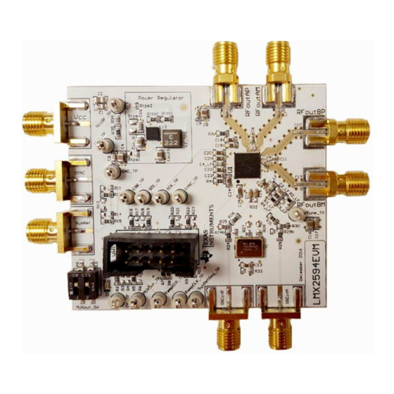
Figure 1. LMX2595EVM
....................................................................................................
.............................................................................................................
........................................................................................
........................................................................................
.....................................................................................................
..........................................................................................................
....................................................................................................
...........................................................................................
.......................................................................................
.................................................................................................
.................................................................................................
LMX2595 EVM Instructions - 19-GHz Wideband Low Noise PLL With
Copyright © 2017, Texas Instruments Incorporated
PLL With Integrated VCO
Contents
.....................................................................
User's Guide
SNAU219 - June 2017
3
4
8
10
11
12
13
15
16
18
21
23
1
Integrated VCO
Advertisement
Table of Contents

Related Manuals for Texas Instruments LMX2595EVM


Summary of Contents for Texas Instruments LMX2595EVM
-
Page 1: Table Of Contents
Appendix E Connecting Reference Pro ....................Appendix F Ramping Feature ....................Appendix G SYSREF Feature SNAU219 – June 2017 LMX2595 EVM Instructions – 19-GHz Wideband Low Noise PLL With Integrated VCO Submit Documentation Feedback Copyright © 2017, Texas Instruments Incorporated... - Page 2 Appendix J: Using the VCO Doubler Trademarks All trademarks are the property of their respective owners. LMX2595 EVM Instructions – 19-GHz Wideband Low Noise PLL With SNAU219 – June 2017 Integrated VCO Submit Documentation Feedback Copyright © 2017, Texas Instruments Incorporated...
-
Page 3: Evaluation Board Setup
(a) Connect USB cable from laptop or PC to USB port in Reference Pro. This provides power to Reference Pro Board and communication with TICS GUI (b) Connect 10 pin ribbon cable from Reference Pro to LMX2595EVM as shown above. 4. Output: (a) Connect RFoutAM or RFoutAP to a phase noise Analyzer. -
Page 4: Evm Description
NAME RAMPDIR and CE (Choose with Resistors on Board) MUXout Not Used RampCLK SysRefReq SYNC LMX2595 EVM Instructions – 19-GHz Wideband Low Noise PLL With SNAU219 – June 2017 Integrated VCO Submit Documentation Feedback Copyright © 2017, Texas Instruments Incorporated... - Page 5 The LD switch must be on to enable Lock indicator: Figure 4. LD Lock Detect SNAU219 – June 2017 LMX2595 EVM Instructions – 19-GHz Wideband Low Noise PLL With Integrated VCO Submit Documentation Feedback Copyright © 2017, Texas Instruments Incorporated...
- Page 6 4. You are now ready to use this software. Verify that you can communicate with Reference Pro. Select interface under USB communications: Figure 6. USB Communications on TICS Pro LMX2595 EVM Instructions – 19-GHz Wideband Low Noise PLL With SNAU219 – June 2017 Integrated VCO Submit Documentation Feedback Copyright © 2017, Texas Instruments Incorporated...
- Page 7 5. Click on identify and you will see the LED (MSP430 Supplied) Blink on Reference Pro Figure 7. USB Communication Between TICS Pro and Reference Pro SNAU219 – June 2017 LMX2595 EVM Instructions – 19-GHz Wideband Low Noise PLL With Integrated VCO Submit Documentation Feedback Copyright © 2017, Texas Instruments Incorporated...
-
Page 8: Bringing Lmx2595 To A Lock State
Load the default mode by selecting it as shown in Figure Figure 8. TICS Pro GUI LMX2595 Default Configuration LMX2595 EVM Instructions – 19-GHz Wideband Low Noise PLL With SNAU219 – June 2017 Integrated VCO Submit Documentation Feedback Copyright © 2017, Texas Instruments Incorporated... - Page 9 Reset box. After the reset, Write all registers as shown in Figure Figure 9. TICS Pro Write All Registers SNAU219 – June 2017 LMX2595 EVM Instructions – 19-GHz Wideband Low Noise PLL With Integrated VCO Submit Documentation Feedback Copyright © 2017, Texas Instruments Incorporated...
-
Page 10: Current Loop Filter Configuration
For detailed design and simulation, see the PLLatinum Sim Tool. For application notes, blogs,or videos on our products, see http://www.ti.com/pll. LMX2595 EVM Instructions – 19-GHz Wideband Low Noise PLL With SNAU219 – June 2017 Integrated VCO Submit Documentation Feedback Copyright © 2017, Texas Instruments Incorporated... -
Page 11: Key Results To Expect
This assumes that the input reference is very clean, such as a 100-MHz Wenzel oscillator. A signal generator is NOT sufficiently clean. The LMX2595 requires an external reference. SNAU219 – June 2017 LMX2595 EVM Instructions – 19-GHz Wideband Low Noise PLL With Integrated VCO Submit Documentation Feedback Copyright © 2017, Texas Instruments Incorporated... -
Page 12: Appendix A Schematic
Appendix A SNAU219 – June 2017 Schematic Figure 12. Schematic Schematic SNAU219 – June 2017 Submit Documentation Feedback Copyright © 2017, Texas Instruments Incorporated... -
Page 13: Appendix B Bill Of Materials
Labels, 0.650" W x 0.200" H - Brady THT-14-423-10 10,000 per roll Switch, SPST, Slide, Off-On, 2 MUXout_SW CTS Electrocomponents 219-2MST Pos, 0.1 A, 20 V, SMD SNAU219 – June 2017 Bill of Materials Submit Documentation Feedback Copyright © 2017, Texas Instruments Incorporated... - Page 14 RES, 51, 5%, 0.1 W, 0603 Vishay-Dale CRCW060351R0JNEA R27, R28 RES, 140, 1%, 0.1 W, 0603 Vishay-Dale CRCW0603140RFKEA Rtps RES, 0, 5%, 0.125 W, 0805 Vishay-Dale CRCW08050000Z0EA Bill of Materials SNAU219 – June 2017 Submit Documentation Feedback Copyright © 2017, Texas Instruments Incorporated...
-
Page 15: Appendix C Board Layers Stack-Up
Appendix C SNAU219 – June 2017 Board Layers Stack-Up Total Board thickness is 62 mils. Figure 13. Board Layer Stack-Up SNAU219 – June 2017 Board Layers Stack-Up Submit Documentation Feedback Copyright © 2017, Texas Instruments Incorporated... -
Page 16: Appendix D Changing Reference Oscillator And Setup
1. Switch R24b to R24. 2. Switch R29b to R29 3. Must remove R33 to remove power from oscillator Figure 14. Single-Ended Reference Configuration Changing Reference Oscillator and Setup SNAU219 – June 2017 Submit Documentation Feedback Copyright © 2017, Texas Instruments Incorporated... - Page 17 3. Must remove R33 to remove power from oscillator 4. Populate R25 and R30. 5. Remove R32 Figure 15. Differential Reference Configuration SNAU219 – June 2017 Changing Reference Oscillator and Setup Submit Documentation Feedback Copyright © 2017, Texas Instruments Incorporated...
-
Page 18: Appendix E Connecting Reference Pro
Serial Interface should be disabled Figure 17. LMX2595EVM Setup With Reference Pro The LMK61PD0A2 has several control pins dedicated for control of output format, output frequency, and output enable control. These control pins can be configured through the jumpers shown in... - Page 19 100-Ω differential termination (R31) is provided on Reference Pro PCB. Removing the differential termination on the EVM is possible if the differential termination is available on the receiver. SNAU219 – June 2017 Connecting Reference Pro Submit Documentation Feedback Copyright © 2017, Texas Instruments Incorporated...
- Page 20 0 Ω R27, R30, R31 R25, R28 0 Ω 50 Ω R26, R29 C24, C25 0.01 uF R27. R30, R31 Figure 18. LMK61PD0A2 Output Termination Connecting Reference Pro SNAU219 – June 2017 Submit Documentation Feedback Copyright © 2017, Texas Instruments Incorporated...
-
Page 21: Appendix F Ramping Feature
VCO is ramping from 8 to 10 GHz and being dividing by 4 so that it can be seen with the HP53310A. This can be set up on the ramp GUI tab. Figure 19. Ramping Example Tics SNAU219 – June 2017 Ramping Feature Submit Documentation Feedback Copyright © 2017, Texas Instruments Incorporated... - Page 22 Ramping Example Waveform www.ti.com Figure 20. Ramping Example Ramping Feature SNAU219 – June 2017 Submit Documentation Feedback Copyright © 2017, Texas Instruments Incorporated...
-
Page 23: Appendix Gsysref Feature
Figure 21. Perform Sync For SysRef 3. Configure TICS Pro PLL tab for SysRef • Check the SYSREF_EN box • Change OUTB_MUX to SysRef • Uncheck the OUT_PD box SNAU219 – June 2017 SYSREF Feature Submit Documentation Feedback Copyright © 2017, Texas Instruments Incorporated... - Page 24 4. Confirm the Interpolator Frequency is between 800 MHz and 1500 MHz • If not, change the SYSREF_DIV_PRE drop-down to Div2 or Div4 to reach an appropriate Interpolator Frequency for the current configuration SYSREF Feature SNAU219 – June 2017 Submit Documentation Feedback Copyright © 2017, Texas Instruments Incorporated...
- Page 25 Figure 23. Interpolator Frequency For SysRef 5. Go to User Controls in the side bar and check the SysRefReq box under the Pins section SNAU219 – June 2017 SYSREF Feature Submit Documentation Feedback Copyright © 2017, Texas Instruments Incorporated...
- Page 26 Appendix G www.ti.com Figure 24. Check SysRefReq Box on User Controls Tab 6. To modify SysRef Frequency, change the value in the SYSREF_DIV box SYSREF Feature SNAU219 – June 2017 Submit Documentation Feedback Copyright © 2017, Texas Instruments Incorporated...
- Page 27 User Controls tab RFOUTB will repeat external input to SysRefReq pin. Output will be • Uncheck SysRefReq Repeater reclocked to LMX2595 internal Frequency • Check SysRef_Repeat SNAU219 – June 2017 SYSREF Feature Submit Documentation Feedback Copyright © 2017, Texas Instruments Incorporated...
- Page 28 HIGH (the low indicates the instant calibration is triggered and running, then high is when done calibration). Adjust the time scale to capture the pulse (approximately 300 µs to start) Figure 26. Unassisted Calibration TICS VCO Calibration SNAU219 – June 2017 Submit Documentation Feedback Copyright © 2017, Texas Instruments Incorporated...
- Page 29 Appendix H www.ti.com Figure 27. Unassisted Calibration Plot SNAU219 – June 2017 VCO Calibration Submit Documentation Feedback Copyright © 2017, Texas Instruments Incorporated...
- Page 30 4. DC-DC circuitry was optimized for efficiency for 5 to 8 V, but a voltage of 3.3 V to 17 V can be applied to VCC SMA after resistor network is configured correctly from steps above. Enabling Onboard DC-DC Buck Converter (TPS62150) SNAU219 – June 2017 Submit Documentation Feedback Copyright © 2017, Texas Instruments Incorporated...
- Page 31 Appendix J SNAU219 – June 2017 Appendix J: Using the VCO Doubler Figure 29. VCO Frequency Doubler Setup in TICSPro SNAU219 – June 2017 Appendix J: Using the VCO Doubler Submit Documentation Feedback Copyright © 2017, Texas Instruments Incorporated...
- Page 32 Appendix J www.ti.com Figure 30. 18 GHz Phase Noise using VCO Doubler Appendix J: Using the VCO Doubler SNAU219 – June 2017 Submit Documentation Feedback Copyright © 2017, Texas Instruments Incorporated...
- Page 33 STANDARD TERMS FOR EVALUATION MODULES Delivery: TI delivers TI evaluation boards, kits, or modules, including any accompanying demonstration software, components, and/or documentation which may be provided together or separately (collectively, an “EVM” or “EVMs”) to the User (“User”) in accordance with the terms set forth herein.
- Page 34 FCC Interference Statement for Class B EVM devices NOTE: This equipment has been tested and found to comply with the limits for a Class B digital device, pursuant to part 15 of the FCC Rules. These limits are designed to provide reasonable protection against harmful interference in a residential installation.
- Page 35 【無線電波を送信する製品の開発キットをお使いになる際の注意事項】 開発キットの中には技術基準適合証明を受けて いないものがあります。 技術適合証明を受けていないもののご使用に際しては、電波法遵守のため、以下のいずれかの 措置を取っていただく必要がありますのでご注意ください。 1. 電波法施行規則第6条第1項第1号に基づく平成18年3月28日総務省告示第173号で定められた電波暗室等の試験設備でご使用 いただく。 2. 実験局の免許を取得後ご使用いただく。 3. 技術基準適合証明を取得後ご使用いただく。 なお、本製品は、上記の「ご使用にあたっての注意」を譲渡先、移転先に通知しない限り、譲渡、移転できないものとします。 上記を遵守頂けない場合は、電波法の罰則が適用される可能性があることをご留意ください。 日本テキサス・イ ンスツルメンツ株式会社 東京都新宿区西新宿6丁目24番1号 西新宿三井ビル 3.3.3 Notice for EVMs for Power Line Communication: Please see http://www.tij.co.jp/lsds/ti_ja/general/eStore/notice_02.page 電力線搬送波通信についての開発キットをお使いになる際の注意事項については、次のところをご覧ください。http:/ /www.tij.co.jp/lsds/ti_ja/general/eStore/notice_02.page 3.4 European Union 3.4.1 For EVMs subject to EU Directive 2014/30/EU (Electromagnetic Compatibility Directive): This is a class A product intended for use in environments other than domestic environments that are connected to a low-voltage power-supply network that supplies buildings used for domestic purposes.
- Page 36 Notwithstanding the foregoing, any judgment may be enforced in any United States or foreign court, and TI may seek injunctive relief in any United States or foreign court. Mailing Address: Texas Instruments, Post Office Box 655303, Dallas, Texas 75265 Copyright © 2017, Texas Instruments Incorporated...
- Page 37 IMPORTANT NOTICE FOR TI DESIGN INFORMATION AND RESOURCES Texas Instruments Incorporated (‘TI”) technical, application or other design advice, services or information, including, but not limited to, reference designs and materials relating to evaluation modules, (collectively, “TI Resources”) are intended to assist designers who are developing applications that incorporate TI products;...
- Page 38 Mouser Electronics Authorized Distributor Click to View Pricing, Inventory, Delivery & Lifecycle Information: Texas Instruments LMX2595EVM...