Advertisement
Table of Contents
- 1 Important Safety Instructions
- 2 Table of Contents
- 3 Installation Process
- 4 Outdoor Units Information
- 5 Before Installation
- 6 Select the Best Location
- 7 Installation Space
- 8 Installation
- 9 Refrigerant Piping
- 10 Electrical Wiring
- 11 Test Run
- 12 Caution for Refrigerant Leak
- 13 Installation Guide at the Seaside
- Download this manual
QUICK MANUAL
AIR
CONDITIONER
Please read this installation manual completely before installing the product.
Installation work must be performed in accordance with the national wiring standards by
authorized personnel only.
Please retain this installation manual for future reference after reading it thoroughly.
Original instruction
[Representative] LG Electronics Inc. EU Representative : LG Electronics European Shared Service Center B.V.
Krijgsman 1, 1186 DM Amstelveen, The Netherlands
[Manufacturer] LG Electronics Inc. Changwon 2nd factory 84, Wanam-ro, Seongsan-gu, Changwon-si,
Gyeongsangnam-do, KOREA
P/NO : MFL67891402
www.lg.com
Advertisement
Table of Contents

Related Manuals for LG ARUN50GS2A


Summary of Contents for LG ARUN50GS2A
- Page 1 Please retain this installation manual for future reference after reading it thoroughly. Original instruction [Representative] LG Electronics Inc. EU Representative : LG Electronics European Shared Service Center B.V. Krijgsman 1, 1186 DM Amstelveen, The Netherlands [Manufacturer] LG Electronics Inc. Changwon 2nd factory 84, Wanam-ro, Seongsan-gu, Changwon-si,...
-
Page 2: Important Safety Instructions
TIPS FOR SAVING ENERGY intended for use by a qualified service tech- nician familiar with safety procedures and Here are some tips that will help you minimize the power consumption equipped with the proper tools and test in- when you use the air conditioner. You can use your air conditioner struments. - Page 3 the original refrigerant, the refrigerant cycle ter. may malfunction and the unit may be dam- - There is risk of fire or electric shock. aged. • Be cautious not to touch the sharp edges • Do not reconstruct to change the settings of when installing.
- Page 4 medical treatment or image broadcasting. - Starting operation immediately after turn- ing on the main power switch can result in • Do not install the product where it is ex- severe damage to internal parts. Keep the posed to sea wind (salt spray) directly. power switch turned on during the opera- - It may cause corrosion on the product.
-
Page 5: Table Of Contents
TABLE OF CONTENTS INSTALLATION PROCESS Indicate clearly who is to be responsible for switch settings Determination of division work TIPS FOR SAVING ENERGY Make relationship between outdoor, indoor, remote controller, and Preparation of contract drawings option connections clear. (Prepare control circuit diagram) IMPORTANT SAFETY INSTRUCTIONS Take account of INSTALLATION PROCESS... -
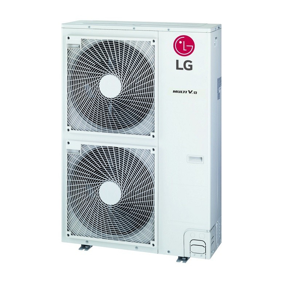
Page 6: Outdoor Units Information
950 x 1,380 x 330 950 x 1,380 x 330 950 x 1,380 x 330 Active Filter 37.4 x 54.3 x 13.0 37.4 x 54.3 x 13.0 37.4 x 54.3 x 13.0 Liquid Pipes ARUN40LS2A ARUN40LS2B inch Ø9.52 Ø9.52 Ø9.52 Heat ARUN50GS2A ARUV50LS2A ARUN50LS2B ARUN40GS2A Connecting Pump ARUN60GS2A Pipes ARUN60LS2A ARUN60LS2B Gas Pipes inch Ø15.88... -
Page 7: Select The Best Location
Transporting the Unit Select installation location considering following conditions to avoid bad condition when additionally performing defrost operation. - When carrying the suspended, unit pass the ropes between legs of - Install the outdoor unit at a place well ventilated and having a lot of base panel under the unit. -
Page 8: Installation Space
INSTALLATION SPACE In case of obstacles on the suction and the discharge side Obstacle height of discharge side is higher than the unit The following values are the least space for installation. If any service area is needed for service according to field circum- - Stand alone installation stance, obtain enough service space. -
Page 9: Installation
Collective / Continuous Installation for roof top use INSTALLATION Space required for collective installation and continuous installation: Foundation for Installation When installing several units, leave space between each block as shown below considering passage for air and people. - Check the strength and level of the installation ground so that the - One row of stand alone installation unit will not cause any operating vibration or noise after installation. - Page 10 Unit : mm(inch) Opening shutoff valve Pipe " A " Indoor unit Remove the cap and turn the valve counter clockwise with the [kW(Btu/h] Liquid Liquid wrench. 1.6~1.8 1.1~1.3 <5.6(19,100) 12.7(1/2) 6.35(1/4) Turn it until the shaft stops. (0.63~0.71) (0.43~0.51) Do not apply excessive force to the shutoff valve.
-
Page 11: Refrigerant Piping
REFRIGERANT PIPING CAUTION • You should not dame pipe/base during the work of pipe knock U3 Chassis (2 Fan Model) out. • Operate piping work removing burr after pipe knock out. Connecting the pipes to the outdoor unit Braze suitable field piping with service valve of gas pipe. Preventing foreign objects from entering (Figure 4) - Plug the pipe through-holes with putty or insulation material(procured locally)to stop up all gaps,as shown in the figure 3. - Page 12 Direction to open Direction to open <Liquid pipe> <Gas pipe> CAUTION Refrigerant pipe connection torque Use the following materials for refrigerant piping. Pipe external 6.35mm 9.52mm 12.7mm 15.88mm • Material: Seamless phosphorous deoxidized copper pipe • Wall thickness : Comply with the relevant local and national regu- diameter (1/4") (3/8")
- Page 13 The Multi V will stop due to an abnormality like excessive or insuffi- No. Piping parts Name Selection of pipe size cient refrigerant. At such a time, always properly charge the unit. When servicing, always check the notes concerning both the piping Size of main pipe length and the amount of additional refrigerant.
- Page 14 Total pipe length = A+a+b+c+d+e+f ≤ 300m WARNING Longest pipe length Equivalent pipe length(*) It is recommended that difference of piping length for pipes con- nected to the Indoor Unit is A+f ≤ 150m A+f ≤ 175m minimized. Performance difference between Indoor Units may Longest pipe length after 1st branch occur.
- Page 15 Distribution Method CAUTION If a negative result is obtained from the calculation, no refrigerant Line Distribution needs to be added. WARNING 3rd main pipe distribution • Regulation for refrigerant leakage : the amount of refrigerant leakage should satisfy the following equation for human safety.
- Page 16 Branch pipe Fitting - Joints between branch and pipe should be sealed with the tape in- cluded in each kit. Y branch Tape Ⓐ To Branch Piping or Indoor Unit Ⓑ To Outdoor Unit Insulator Insulator of field pipe - Ensure that the branch pipes are attached horizontally or vertically (see the diagram below.) Horizontal Facing...
- Page 17 NOTE Header [unit:mm] If the ambient temperature differs between the time when pressure is applied and when the pressure drop is checked, apply the following Models Gas pipe Liquid pipe correction factor There is a pressure change of approximately 0.1 kg/cm (0.01 MPa) for each 1°C of temperature difference.
- Page 18 Thermal insulation of refrigerant piping WARNING • If the primary charging is not performed after vacuum, wet air Be sure to give insulation work to refrigerant piping by covering liquid may go into the outdoor unit. If air is mixed with the refrigerant, pipe and gas pipe separately with enough thickness heat-resistant poly- the refrigerant cycle may malfunction and the unit may be dam- ethylene, so that no gap is observed in the joint between indoor unit...
-
Page 19: Electrical Wiring
Penetrations CAUTION Inner wall (concealed) Outer wall Outer wall (exposed) The Power cord connected to the unit should be selected according to the following specifications. Outdoor Unit Floor (fireproofing) Penetrating portion on fire Roof pipe shaft Indoor Indoor limit and boundary wall Unit Unit Remote... - Page 20 Communication and Power Cables Wiring of main power supply and equipment capacity Communication cable - Types : shielding wire Outdoor unit (1Ø, 220~240V, 50Hz/ 1Ø, 220V, 60Hz/ 3Ø, 380~415V, - Cross section : 1.0 ~ 1.5 mm 50Hz/ 3Ø, 380V, 60Hz) - Insulation material : PVC Indoor unit (1Ø,220V, 50/60Hz) - Maximum allowable temperature: 60°C...
- Page 21 How to connect wiring (U3 Chassis, 2 Fan Model) 3Ø, 50Hz - Connect power supply wire to terminal block of control case using clamps on the supporter and control case as shown figure right. ARUN(V)40LS2*, ARUN(V)50LS2*, ARUN(V)60LS2* - Connect communication wire to main PCB terminal block using clamps on the supporter and main PCB case as shown figure right.
- Page 22 Location of DIP Switch (U3 Chassis, 2 Fan Between Indoor and Outdoor unit (U3 Chassis, 2 Fan Model) SODU INTERNET DRY1 DRY2 GND Model) B A B A Main PCB Between Indoor and Outdoor unit SW02V (U4 Chassis, 1 Fan Model) Auto addressing 7 - Segment Outdoor unit...
- Page 23 Configuration of DIP Switch (U3 Chassis, 2 Configuration of DIP Switch (U4 Chassis, 1 Fan Fan Model) Model) SW01N SW01B SW02B 10 11 12 13 14 Short Pipe Length Short Pipe Length Long Pipe Length Long Pipe Length Refrigerant Auto Charging Cool/Heat Selector Refrigerant Checking Forced Oil Return...
- Page 24 The Procedure of Automatic Addressing The Procedure of Automatic Addressing Power On All DIP switch should be off before auto adressing Power On All DIP switch should be off before auto adressing Waiting 3 minutes Waiting 3 minutes Press SW02V for 5 s Press SW02N for 5 s Auto addressing start 7-segment LED...
-
Page 25: Test Run
In case, try to set mode without Cool/Heat Selector and try to use Group Number setting for Indoor Units other switch except from LG Outdoor Cool/Heat Selector in field. - Confirm the power of whole system(Indoor Unit, Outdoor Unit) is Connect signal terminal block as below figure and description. - Page 26 Sensor Checking Function (U3 Chassis, 2Fan Displaying error content Model) Indoor unit error display - 1st and 2nd number represents indoor unit number. Sensor checking function judges whether the current temperature of Indoor unit number follows auto addressing number. indoor and outdoor unit sensors is right or not. It checks 3 indoor tem- - Last number represents sensor.
- Page 27 Refrigerant Auto Charging Function (U3 Chas- Error contents about auto refrigerant charging function sis, 2Fan Model) : Temperature Range Error (In case that IDU or ODU is out of range) This function charges appropriate amount of refrigerant automatically through cycle operation. : Low Pressure Descent Error It can be used when refrigerant amount Isn't certain because of SVC (In case the system runs at low pressure limit for over 10...
- Page 28 CAUTION CAUTION • Guaranteed Temperature range(Error occurs out of guaranteed tem- • Request installer to set the function during installation. perature range) • In case the function is not used, set the DIP switch OFF and reset IDU : 20~32°C the power.
- Page 29 Self-Diagnosis Function (U3 Chassis, 2 Fan Model) Error Indicator - This function indicates types of failure in self-diagnosis and occurrence of failure for air condition. - Error mark is displayed on display window of indoor units and wired remote controller, and 7-segment LED of outdoor unit control board as shown in the table.
- Page 30 Display Title Cause of Error Outdoor Unit Inverter Compressor CT Sensor open or short Outdoor Unit Inverter Compressor CT Sensor Fault Outdoor Unit Inverter Compressor Discharge Temperature Sensor Outdoor Unit Inverter Compressor Discharge Tem- open or short perature Sensor Fault Outdoor Unit Low Pressure Sensor open or short Outdoor Unit Low Pressure Sensor Fault Outdoor Unit High Pressure Sensor open or short...
- Page 31 Self-Diagnosis Function (U4 Chassis, 1FAN Model) Error Indicator - This function indicates types of failure in self-diagnosis and occurrence of failure for air condition. - Error mark is displayed on display window of indoor units and wired remote controller, and red/green LED of outdoor unit control board as shown in the table.
- Page 32 Display Title Cause of Error Outdoor Unit Inverter Compressor High Discharge System is turned off by outdoor unit Inverter Compressor High Dis- Temperature charge Temperature High Pressure of Outdoor Unit System is turned off by excessive increase of high pressure of out- door unit Low Pressure of Outdoor Unit System is turned off by excessive decrease of low pressure of out-...
-
Page 33: Caution For Refrigerant Leak
CAUTION FOR REFRIGERANT LEAK Calculate refrigerant concentration Total amount of replenishedrefrigerant in refrigerant facility (kg) The installer and system specialist shall secure safety against leakage = Refrigerant concentration(kg/m according to local regulations or standards. Capacity of smallest room The following standards may be applicable if local regulations are not whereindoor unit is installed (m (R410A) available. -
Page 34: Installation Guide At The Seaside
Select a well-drained place. • If you can’t meet above guide line in the seaside installation, please contact LG Electronics for the additional anticorrosion treatment. • Periodic ( more than once/year ) cleaning of the dust or salt...