Symbol AP-5131 Product Reference Manual
Symbol technologies network router user manual
Hide thumbs
Also See for AP-5131:
- Product reference manual (456 pages) ,
- Installation manual (48 pages) ,
- Product reference manual (100 pages)
Table of Contents
Advertisement
Quick Links
Download this manual
See also:
Installation Manual
Advertisement
Table of Contents

Related Manuals for Symbol AP-5131


Summary of Contents for Symbol AP-5131
- Page 1 AP-5131 Access Point Product Reference Guide...
- Page 3 AP-5131 Access Point Product Reference Guide 72E-94168-01 Revision A November 2006...
- Page 5 Symbol does not assume any product liability arising out of, or in connection with, the application or use of any product, circuit, or application described herein. No license is granted, either expressly or by implication, estoppel, or otherwise under any Symbol Technologies, Inc., intellectual property rights. An implied license only exists for equipment, circuits, and subsystems contained in Symbol products.
-
Page 7: Table Of Contents
New AP-5131 Features........ - Page 8 AP-5131 Access Point Product Reference Guide Single or Dual Mode Radio Options....... . . 1-6 Separate LAN and WAN Ports .
- Page 9 Placement of the AP-5131 ........
- Page 10 AP-5131 Access Point Product Reference Guide Testing Connectivity ..........3-13 Where to Go from Here? .
- Page 11 Resetting the AP-5131 Password ........6-4...
- Page 12 AP-5131 Access Point Product Reference Guide Mapping Users to Groups........6-71 Defining the User Access Policy.
- Page 13 Mesh Networking Overview ......... . . 9-1 The AP-5131 Client Bridge Association Process ......9-3 Spanning Tree Protocol (STP) .
- Page 14 Frequently Asked VPN Questions........B-14 Replacing an AP-4131 with an AP-5131....... . . B-19...
-
Page 15: About This Guide
Introduction This guide provides configuration and setup information for the AP-5131 model access point. Document Conventions The following document conventions are used in this document: NOTE Indicate tips or special requirements. CAUTION Indicates conditions that can cause equipment damage or data loss. -
Page 16: Notational Conventions
If the problem cannot be solved over the phone, you may need to return your equipment for servicing. If that is necessary, you will be given specific instructions. Symbol Technologies is not responsible for any damages incurred during shipment if the approved shipping container is not used. Shipping the units improperly can possibly void the warranty. -
Page 17: Chapter 1. Ap-5131 Introduction
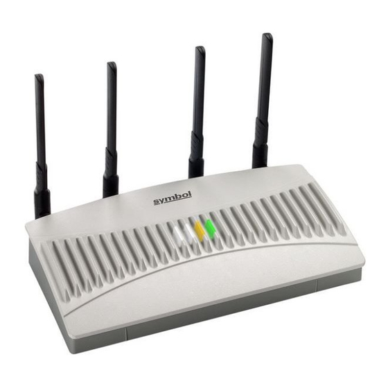
The Symbol AP-5131 Access Point (AP) provides a bridge between Ethernet wired LANs or WANs and wireless networks. It provides connectivity between Ethernet wired networks and radio-equipped mobile units (MUs). MUs include the full line of Symbol terminals, bar-code scanners, adapters (PC cards, Compact Flash cards and PCI adapters) and other devices. -
Page 18: New Ap-5131 Features
Once the association/authentication process is complete, the wireless client adds the connection as a port on its bridge module. This causes the AP-5131 (in client bridge mode) to begin forwarding configuration packets to the base bridge. An AP-5131 in base bridge mode allows the AP-5131 radio to accept client bridge connections. -
Page 19: Additional Lan Subnet
The main AP-5131 LAN screen now allows the user to select either LAN1 or LAN2 as the active LAN over the AP-5131’s Ethernet port. Both LANs can still be active at any given time, but only one can transmit over the AP-5131 physical LAN connection. Each LAN has a separate configuration screen (called LAN 1 and LAN 2 by default) accessible under the main LAN screen. -
Page 20: On-Board Radius Server Authentication
Rather than rely on built-in 802.11security features to control AP-5131 association privileges, you can configure a WLAN with no WEP (an open network). The AP-5131 issues an IP address to the user using a DHCP server, authenticates the user and grants the user to access the Internet. -
Page 21: Routing Information Protocol (Rip)
1.1.6 Manual Date and Time Settings As an alternative to defining a NTP server to provide AP-5131 system time, the AP-513 can now have its date and time set manually. A new Manual Date/Time Setting screen can be used to set the AP-5131 time using a Year-Month-Day HH:MM:SS format. -
Page 22: Feature Overview
One or two possible configurations are available on the AP-5131 depending on which model is purchased. If the AP-5131 is manufactured as a single radio access point, the AP-5131 enables you to configure the single radio for either 802.11a or 802.11b/g. -
Page 23: Separate Lan And Wan Ports
Viewing LAN Statistics on page 1.2.3 Multiple Mounting Options The AP-5131 rests on a flat surface, attaches to a wall, mounts under a ceiling or above a ceiling (attic). Choose a mounting option based on the physical environment of the coverage area. Do not mount the AP-5131 in a location that has not been approved in an AP-5131 radio coverage site survey. -
Page 24: Sixteen Configurable Wlans
AP-5131 Access Point Product Reference Guide For an overview of the Radio 1 (2.4 GHz) and Radio 2 (5.2 GHz) antennas supported on the AP-5131’s Reverse SMA (RSMA) connectors, see 1.2.5 Sixteen Configurable WLANs A Wireless Local Area Network (WLAN) is a data-communications system that flexibly extends the functionalities of a wired LAN. -
Page 25: Quality Of Service (Qos) Support
The AP-5131 QoS implementation provides applications running on different wireless devices a variety of priority levels to transmit data to and from the AP-5131. Equal data transmission priority is fine for data traffic from applications such as Web browsers, file transfers or email, but is inadequate for multimedia applications. -
Page 26: Kerberos Authentication
The server prompts the AP for proof of identity (supplied to the AP-5131 by the user) and then transmits the user data back to the server to complete the authentication. -
Page 27: Wep Encryption
Wired Equivalent Privacy (WEP) is an encryption security protocol specified in the IEEE Wireless Fidelity (Wi-Fi) standard, 802.11b and supported by the AP-5131 AP. WEP encryption is designed to provide a WLAN with a level of security and privacy comparable to that of a wired LAN. The level of protection provided by WEP encryption is determined by the encryption key length and algorithm. -
Page 28: Keyguard Encryption
(similar to TKIP). Like TKIP, the keys the administrator provides are used to derive other keys. Messages are encrypted using a 128-bit secret key and a 128-bit block of data. the end result is an encryption scheme as secure as any the AP-5131 provides. Configuring KeyGuard Encryption on page... -
Page 29: Firewall Security
6-50. 1.2.9 VLAN Support A Virtual Local Area Network (VLAN) is a means to electronically separate data on the same AP-5131 from a single broadcast domain into separate broadcast domains. By using a VLAN, you can group by logical function instead of physical location. There are 16 VLANs supported on the AP-5131. An... -
Page 30: Multiple Management Accessibility Options
• MIB (Management Information Base) • Command Line Interface (CLI) accessed via RS-232 or Telnet. Use the AP-5131 DB-9 serial port for direct access to the command-line interface from a PC. Use Symbol's Null-Modem cable (Part No. 25-632878-0) for the best fitting connection. -
Page 31: Power-Over-Ethernet Support
• Symbol-CC-WS2000-MIB-2.0 (standard Symbol MIB file) • Symbol-AP-5131-MIB (AP-5131 specific MIB file) The AP-5131 SNMP agent functions as a command responder and is a multilingual agent responding to SNMPv1, v2c and v3 managers (command generators). The factory default configuration maintains SNMPv1/2c support of the community names, hence providing backward compatibility. -
Page 32: Voice Prioritization
AP-5131 Access Point Product Reference Guide 1.2.15 Voice Prioritization Each AP-5131 WLAN has the capability of having its QoS policy configured to prioritize the network traffic requirements for associated MUs. A WLAN QoS page is available for each enabled WLAN on either the AP-5131 802.11a or 802.11b/g radio. -
Page 33: Transmit Power Control
The AP-5131 has the ability to restore its default configuration or a partial default configuration with the exception of current WAN and SNMP settings. Restoring the default configuration is a good way to create new WLANs if the MUs the AP-5131 supports have been moved to different radio coverage areas. -
Page 34: Dhcp Support
Because BOOTP and DHCP interoperate, whichever responds first becomes the server that allocates information. The AP-5131 can be set to only accept replies from DHCP or BOOTP servers or both (this is the default setting). Disabling DHCP disables BOOTP and DHCP and requires network settings to be set manually. -
Page 35: Cellular Coverage
When in a particular cell, the MU associates and communicates with the AP-5131 supporting the radio coverage area of that cell. Adding AP-5131’s to a single LAN establishes more cells to extend the range of the network. Configuring the same ESSID (Extended Service Set Identifier) on all AP-5131s makes them part of the same Wireless LAN. -
Page 36: Mac Layer Bridging
AP-5131 provides better signal strength and lower MU load distribution. If the MU does not find an AP-5131 with a workable signal, it can perform a scan to find any AP. As MUs switch APs, the AP updates its association statistics. -
Page 37: Media Types
The RS-232 serial port provides a Command Line Interface (CLI) connection. The serial link supports a direct serial connection. The AP-5131 is a Data Terminal Equipment (DTE) device with male pin connectors for the RS-232 port. Connecting the AP-5131 to a PC requires a null modem serial cable. 1.3.4 Direct-Sequence Spread Spectrum Spread spectrum (broadband) uses a narrowband signal to spread the transmission over a segment of the radio frequency band or spectrum. -
Page 38: Mu Association Process
An AP-5131 recognizes MUs as they begin the association process with the AP-5131. An AP-5131 keeps a list of the MUs it services. MUs associate with an AP-5131 based on the following conditions: • Signal strength between the AP-5131and MU •... -
Page 39: Operating Modes
The AP-5131 can operate in a couple of configurations. • Access Point - As an Access Point, the AP-5131 functions as a layer 2 bridge (similar to Symbol’s existing AP-4131 access point). The wired uplink can operate as a trunk and support multiple VLANs. - Page 40 1-24 AP-5131 Access Point Product Reference Guide • MIB (Management Information Base) accessing the AP-5131 SNMP function using a MIB Browser. The AP-5131 CDROM contains the following 2 MIB files: • Symbol-CC-WS2000-MIB-2.0 (standard Symbol MIB file) • Symbol-AP-5131-MIB (AP-5131 specific MIB file) Make configuration changes to AP-5131’s individually.
-
Page 41: Chapter 2. Hardware Installation
An AP-5131 installation includes mounting the AP-5131 on a table-top, wall, ceiling T-bar or above the ceiling (attic or plenum), connecting the AP-5131 to the network (LAN or WAN port connection), connecting antennae and applying power. Installation procedures vary for different environments. -
Page 42: Precautions
• Verify the environment has a continuous temperature range between -20° C to 50° C. 2.2 Package Contents Check package contents for the correct model AP-5131 and applicable AP-5131 accessories. Each available configuration (at a minimum), contains the following: • AP-5131 (two models available) •... - Page 43 AP-5131-13043-WWR AP-5131-40020-WW AP-5131-40021-WWR AP-5131-40022-WW AP-5131-40023-WWR Verify the model indicated on the bottom of the AP-5131 is correct. Contact the Symbol Support Center to report missing or improperly functioning items. Description AP-5131 802.11a+g Dual Radio Access Point AP-5131 Install Guide Power Injector (Part No. AP-PSBIAS-1P2-AFR)
-
Page 44: Requirements
2.3 Requirements The minimum installation requirements for a single-cell, peer-to-peer network: • AP-5131 (either the dual or single radio model) • AP-5131 48 Volt Power Supply (Part No. 50-24000-050) or Symbol power injector (Part No. AP-PSBIAS-1P2-AFR) • a power outlet •... -
Page 45: Site Surveys
Install the AP-5131 in open areas or add access points as needed to improve coverage. Antenna coverage is analogous to lighting. Users might find an area lit from far away to be not bright enough. - Page 46 AP-5131. NOTE On a single-radio AP-5131, Radio 1 can be configured to be either a 2.4 GHz or 5.2 GHz radio. On a dual-radio model, Radio 1 refers to the AP- 5131’s 2.4 GHz radio and Radio 2 refers to the AP-5131 5.2 GHz radio.
- Page 47 The 5.2 GHz antenna suite includes the following models: Symbol Part Number ML-5299-WPNA1-01R ML-5299-HPA1-01R ML-2452-APA2-0 For detailed specifications on the 2.4 GHz and 5.2 GHz antennae mentioned in this section, see section 2.4 GHz Antenna Matrix on page A-4 Antenna Type Panel Antenna 13.0 Wide-Band Omni-Directional...
-
Page 48: Power Options
(Part No. AP-PSBIAS-1P2-AFR) is an integrated AC-DC converter and 802.3af power injector which requires 110-220V AC power to combine low-voltage DC with Ethernet data in a single cable connecting to the AP-5131. The AP-5131 can only use a Power Injector when connected to the LAN port. -
Page 49: Installing The Power Injector
The power injector can be installed free standing, on an even horizontal surface or wall mounted using the power injector’s wall mounting key holes. The following guidelines should be adhered to before cabling the power injector to an Ethernet source and an AP-5131: • Do not block or cover airflow to the power injector. -
Page 50: Power Injector Led Indicators
Green (Blinking) Output voltage source is out of range. For more information and device specifications for the Symbol power injector, refer to the Power Injector Quick Install Guide (Part No. 72-70762-01) available from the Symbol Web site or the AP-5131 Software and documentation CDROM. -
Page 51: Mounting The Ap-5131
2.7 Mounting the AP-5131 The AP-5131 can rest on a flat surface, attach to a wall, mount under a suspended T-Bar or above a ceiling (plenum or attic). Choose one of the following mounting options based on the physical environment of the coverage area. Do not mount the AP-5131 in a location that has not been approved in a site survey. - Page 52 2-12 AP-5131 Access Point Product Reference Guide 4. Cable the AP-5131 using either the Symbol power injector solution or an approved line cord and power supply. CAUTION Do not supply power to the AP-5131 until the cabling of the unit is complete.
-
Page 53: Wall Mounted Installations
5. Verify the behavior of the AP-5131 LEDs. For more information, see 2-20. 6. Return the AP-5131 to an upright position and place it in the location you wish it to operate. Ensure the AP-5131 is sitting evenly on all four rubber feet. - Page 54 Radio 1, and two dots designate the secondary antenna for Radio 1. 8. Cable the AP-5131 using either the Symbol power injector solution or an approved line cord and power supply.
-
Page 55: Suspended Ceiling T-Bar Installations
System Configuration on page 2.7.3 Suspended Ceiling T-Bar Installations A suspended ceiling mount requires holding the AP-5131 up against the T-bar of a suspended ceiling grid and twisting the AP-5131 chassis onto the T-bar. The mounting hardware and tools (customer provided) required to install the AP-5131 on a ceiling T- bar consists of: •... - Page 56 2-16 AP-5131 Access Point Product Reference Guide 4. Cable the AP-5131 using either the Symbol power injector solution or an approved line cord and power supply. CAUTION Do not supply power to the AP-5131 until the cabling of the unit is complete.
-
Page 57: Above The Ceiling (Plenum) Installations
10. Rotate the AP-5131 chassis 45 degrees counter-clockwise. The clips click as they fasten to the T-bar. 11. The AP-5131 is ready to configure. For information on an AP-5131 default configuration, see Getting Started on page System Configuration on page NOTE If the AP-5131 is utilizing remote management antennae, a wire cover can be used to provide a clean finished look to the installation. - Page 58 5. Create a light pipe path hole in the target position on the ceiling tile. 6. Use a drill to make a hole in the tile the approximate size of the AP-5131 LED light pipe. CAUTION Symbol recommends care be taken not to damage the finished surface of the ceiling tile when creating the light pipe hole and installing the light pipe.
- Page 59 Radio 1, and two dots designate the secondary antenna for Radio 1. 13. Attach safety wire (if used) to the AP-5131 safety wire tie point or security cable (if used) to the AP-5131’s lock port.
-
Page 60: Led Indicators
System Configuration on page 2.8 LED Indicators The AP-5131 utilizes seven LED indicators. Five LEDs display within four LED slots on the front of the AP-5131 (on top of the AP-5131 housing) and two LEDs (for above the ceiling installations) are located on the back of the device (the side containing the LAN, WAN and antenna connectors). - Page 61 The five LEDs on the top housing of the AP-5131 are clearly visible in table-top, wall and below ceiling installations. The five AP-5131 top housing LEDs have the following display and functionality: Solid white indicates the Power Status Solid red indicates the immediate attention.
-
Page 62: Setting Up Mus
Conditions 2.9 Setting Up MUs For a discussion of how to initially test the AP-5131 to ensure it can interoperate with the MUs intended for its operational environment, see Testing Connectivity on page Refer to the LA-5030 & LA-5033 Wireless Networker PC Card and PCI Adapter Users Guide, available from the Symbol Web site, for installing drivers and client software if operating in an 802.11a/g... -
Page 63: Chapter 3. Getting Started
The AP-5131 should be installed in an area tested for radio coverage using one of the site survey tools available to the Symbol field service technician. Once an installation site has been identified, the installer should carefully follow the hardware precautions, requirements, mounting guidelines and... -
Page 64: Configuration Options
• For instructions on mounting an AP-5131 to a ceiling T-bar, see Installations on page • For instructions on installing the AP-5131 in an above the ceiling attic space, see Ceiling (Plenum) Installations on page For information on the 802.11a and 802.11b/g radio antenna suite available to the AP-5131, see Antenna Options on page 2-5. -
Page 65: Default Configuration Changes
3.4.1 Connecting to the Access Point using the WAN Port To initially connect to the AP-5131 using the access point’s WAN port: 1. Connect AC power to the AP-5131, as Power-Over-Ether support is not available on the WAN port. 2. Start a browser and enter the AP-5131’s static IP WAN address (10.1.1.1). The default password is “symbol.”... -
Page 66: Connecting To The Access Point Using The Lan Port
5. Enter the default username of “admin” and the default password of “symbol.” As this is the first time you are logging into the AP-5131, you are prompted to enter a new password and set the county code. Refer to available countries two digit country code. -
Page 67: Basic Device Configuration
For the basic setup described in this section, the Java-based Web UI will be used to configure the AP-5131. Use the AP-5131’s LAN interface for establishing a link with the AP-5131. Configure the AP- 5131 as a DHCP client. For optimal screen resolution, set your screen resolution to 1024 x 768 pixels or greater. -
Page 68: Configuring Device Settings
The export function will always export the encrypted Admin User password. The import function will import the Admin Password only if the AP-5131 is set to factory default. If the AP-5131 is not configured to factory default settings, the Admin User password WILL NOT get imported. - Page 69 AP-5131’s country of operation from the drop-down menu The AP-5131 prompts the user for the correct country code on the first login. A warning message also displays stating that an incorrect country settings may result in illegal radio operation.
- Page 70 AP-5131 Access Point Product Reference Guide 4. Optionally enter the IP address of the server used to provide system time to the AP-5131 within the Time Server field. NOTE DNS names are not supported as a valid IP address. The user is required to enter a numerical IP address.
- Page 71 Ethernet (PPPoE) for a high-speed connection that supports this protocol. Most DSL providers are currently using or deploying this protocol. PPPoE is a data-link protocol for dialup connections. PPPoE will allow the AP-5131 to use a broadband modem (DSL, cable modem, etc.) for access to high-speed data networks.
- Page 72 5-1. 8. Enable the radio(s) using the using a single radio AP-5131, enable the radio, then select either 2.4 GHz or 5.2 GHz from RF Band of Operation single-radio AP-5131. If using a dual-radio AP-5131, the user can enable both RF bands. For...
-
Page 73: Configuring Wlan Security Settings
802.11a or 802.11b/g radio. Ensure the radio selected has been enabled (see step 8). c. Even an AP-5131 configured with minimal values must protect its data against theft and corruption. A security policy should be configured for WLAN1 as part of the basic configuration outlined in this guide. - Page 74 Pass Key used to generate Specify a 4 to 32 character pass key and click the button. The AP-5131, other proprietary routers and Symbol MUs use the same algorithm to convert an ASCII string to the same hexadecimal number.
-
Page 75: Testing Connectivity
At this point, you can test the AP-5131 for MU interoperability. 3.5.2 Testing Connectivity Verify the AP-5131’s link with an MU by sending Wireless Network Management Protocol (WNMP) ping packets to the associated MU. Use the Echo Test screen to specify a target MU and configure the parameters of the test. -
Page 76: Where To Go From Here
Echo Test screen and return to the MU Stats Summary screen. 3.5.3 Where to Go from Here? Once basic connectivity has been verified, the AP-5131 can be fully configured to meet the needs of the network and the users it supports. Refer to the following: •... -
Page 77: Chapter 4. System Configuration
Virtual Machine if installed. To connect to the AP, the AP-5131 IP is required. If connected to the AP-5131 using the WAN port, the default static IP address is 10.1.1.1. The default password is “symbol.” If connected to the AP-5131 using the LAN port, the default setting is DHCP client. -
Page 78: Configuring System Settings
AP-5131 Access Point Product Reference Guide NOTE DNS names are not supported as a valid IP address for the AP-5131. The user is required to enter a numerical IP address. System configuration topics include: • Configuring System Settings • Configuring Data Access •... - Page 79 2. Configure the AP-5131 System Settings country of operation and view device version information. System Name Specify a device name for the selecting a name serving as a reminder of the user base the AP-5131 System Location Enter the location of the parameter acts as a reminder of where the AP can be found.
- Page 80 A warning message also displays stating that an incorrect country setting will lead to an illegal use of the AP-5131. Use the pull-down menu to select the country of operation.
- Page 81 System Settings screen. Navigating away from the screen without clicking the Apply button results in all changes to the screen being lost. NOTE The Apply button is not needed for restoring the AP-5131 default configuration or restarting the AP-5131. 6. Click Undo Changes (if necessary) to undo any changes made.
-
Page 82: Configuring Data Access
WAN interfaces and display screens for changing administrator passwords. Use the AP-5131 Access screen checkboxes to enable or disable LAN1, LAN2 and/or WAN access using the protocols and ports listed. If access is disabled, this effectively locks out the administrator from configuring the AP-5131 using that interface. - Page 83 AP-5131 to the client. 3. Refer to the Applet Timeout Disables access to the AP-5131 if no data activity is detected over HTTP/S Timeout Applet HTTPS (port 443) after the user defined interval. Default is 0 Mins. 4. Configure the...
- Page 84 Change Admin Password 8. Click Apply to save any changes to the AP-5131 Access screen. Navigating away from the screen without clicking the Apply button results in all changes to the screen being lost. 9. Click Undo Changes settings displayed on the AP-5131 Access screen to the last saved configuration.
-
Page 85: Managing Certificate Authority (Ca) Certificates
The AP-5131 can import and maintain a set of CA certificates to use as an authentication option for Virtual Private Network (VPN) access. To use the certificate for a VPN tunnel, define a tunnel and select the IKE settings to use either RSA or DES certificates. -
Page 86: Creating Self Certificates For Accessing The Vpn
5. To delete a certificate, select the Id from the drop-down menu and click the 4.3.2 Creating Self Certificates for Accessing the VPN The AP-5131 requires two kinds of certificates for accessing the VPN, CA certificates and self certificates. Self certificates are certificate requests you create, send to a Certificate Authority (CA) to be signed, then import the signed certificate into the management system. - Page 87 Key ID Enter a logical name for the certificate to help distinguish between certificates. The name can be up to 7 characters in length. -> Certificate Mgmt -> Self Certificates screen displays. 4-11 System Configuration from the AP-5131...
- Page 88 4-12 AP-5131 Access Point Product Reference Guide Subject Signature Algorithm Key Length 4. When the form is completed, click the The Certificate Request screen disappears and the ID of the generated certificate request displays in the drop-down list of certificates within the Self Certificates screen.
-
Page 89: Creating A Certificate For Onboard Radius Authentication
The AP-5131 can use its on-board Radius Server to generate certificates to authenticate MUs for use with the AP-5131. In addition, a Windows 2000 or 2003 Server is used to sign the certificate before downloading it back to the AP-5131’s on-board Radius server and loading the certificate for use with the AP-5131. - Page 90 Ensure the Domain name is the name of the CA Server. This value must be set correctly to ensure the certificate is properly generated. Enter the IP address of this AP-5131 (as you are using the AP-5131’s onbard Radius server). Self Certificates...
- Page 91 Signature Algorithm Use the drop-down menu to select the signature algorithm used for the certificate. Options include: • MD5-RSA - Message Digest 5 algorithm in combination with RSA encryption. • SHA1-RSA - Secure Hash Algorithm 1 in combination with RSA encryption. Key Length Defines the length of the key.
- Page 92 4-16 AP-5131 Access Point Product Reference Guide 7. Click the Copy to clipboard 8. Connect to the Windows 2000 or 2003 server used to sign the certificate. 9. Select the Request a certificate 10. Select the Advanced request click Next to continue.
-
Page 93: Configuring Snmp Settings
Internet devices in potentially remote locations. MIB information accessed via SNMP is defined by a set of managed objects called object identifiers (OIDs). An object identifier (OID) is used to uniquely identify each object variable of a MIB. The AP-5131 CDROM contains the following 2 MIB files: •... - Page 94 The remaining portion of the Symbol-AP-5131-MIB contains supplemental information unique to the AP-5131 feature set. If using the Symbol-CC-WS2000-MIB-2.0 and/or Symbol-AP-5131-MIB to configure the AP-5131, use the table below to locate the MIB where the feature can be configured.
- Page 95 The AP-5131 supports SNMP management functions for gathering information from its network components, communicating that information to specified users and configuring the AP-5131. All the fields available within the AP-5131 are also configurable within the MIB.
- Page 96 Symbol recommends considering adding a community definition using a site-appropriate name and access level. Set up a read/write definition (at a minimum) to facilitate full access by the AP-5131 administrator.
- Page 97 OIDs in the MIB. The OID field uses numbers expressed in dot notation. Access Use the read/write (RW) access for the community. Read-only access allows a remote device to retrieve AP-5131 information, while read/write access allows a remote device to modify AP-5131 settings. 3. Configure the SNMP v3 User Definitions SNMP v3 user definitions.
- Page 98 4-22 AP-5131 Access Point Product Reference Guide Passwords Access 4. Specify the users who can read and optionally modify the SNMP-capable client. SNMP Access Control Click the 5. If configuring SNMP v3 user definitions, set the SNMP v3 engine ID.
-
Page 99: Configuring Snmp Access Control
SNMP Access screen to the last saved configuration. 8. Click Logout to securely exit the AP-5131 Symbol Access Point applet. A prompt displays confirming the logout before the applet is closed. For additional SNMP configuration information, see: •... - Page 100 4-24 AP-5131 Access Point Product Reference Guide 2. Configure the SNMP Access Control screen to add the IP addresses of those users receiving SNMP access. Access Control List Edit Delete Enter Start IP and End IP addresses (numerical addresses only, no...
-
Page 101: Enabling Snmp Traps
Trap configuration depends on the network machine that receives the generated traps. SNMP v1/v2c and v3 trap configurations function independently. In a mixed SNMP environment, generated traps can be sent using configurations for both SNMP v1/v2c and v3. To configure SNMP traps on the AP-5131: 1. Select System Configuration AP-5131 menu tree. - Page 102 4-26 AP-5131 Access Point Product Reference Guide 2. Configure the SNMP v1/v2c Trap Configuration modify the following: Delete Destination IP Port Community SNMP Version 3. Configure the SNMP v3 Trap Configuration the following: field (if SNMP v1/v2c Traps are used) to Click to create a new SNMP v1/v2c Trap Configuration entry.
- Page 103 SNMP Trap Configuration screen to the last saved configuration. 6. Click Logout to securely exit the AP-5131 Symbol Access Point applet. A prompt displays confirming the logout before the applet is closed. to create a new SNMP v3 Trap Configuration entry.
-
Page 104: Configuring Specific Snmp Traps
SNMP Traps screen to enable specific traps on the AP-5131. Symbol recommends defining traps to capture unauthorized devices operating within the AP-5131 coverage area. Trap configuration depends on the network machine that receives the generated traps. SNMP v1/v2c and v3 trap configurations function independently. - Page 105 SNMP capable MUs are denied ’s SNMP management functions or data. This can SNMP Access Control field to generate traps when the AP-5131’s link status and a connected device. AP-5131 firewall. A new trap is sent at the...
-
Page 106: Configuring Snmp Rf Trap Thresholds
SNMP Traps screen to the last saved configuration. 8. Click Logout to securely exit the AP-5131 Symbol Access Point applet. A prompt displays confirming the logout before the applet is closed. 4.4.4 Configuring SNMP RF Trap Thresholds... - Page 107 2. Configure the RF Trap Thresholds NOTE Average Bit Speed,% of Non-Unicast, Average Signal, Average Retries,% Dropped and % Undecryptable are not AP-5131 statistics. Enter a maximum threshold for the total throughput in Pps (Packets Pkts/s per second). Throughput Set a maximum threshold for the total throughput in Mbps (Megabits per second).
-
Page 108: Configuring Network Time Protocol (Ntp)
NTP is a client/server implementation. The AP-5131 (an NTP client) periodically synchronizes its clock with a master clock (an NTP server). For example, the AP-5131 resets its clock to 07:04:59 upon reading a time of 07:04:59 from its designated NTP server. - Page 109 Current Time screen was displayed by the user. The Current Time field displays the current time based on the AP-5131 system clock. If NTP is disabled or if there are no servers available, the system time displays the AP-5131 uptime starting at 1970-01-01 00:00:00, with the time and date advancing.
- Page 110 This option is disabled when the Enable NTP on AP-5131 checkbox has been selected, and therefore should be viewed as a second means to define the AP-5131 system time. 4. If using the Manual Date/Time Setting screen to define the AP-5131’s system time, refer to Time Zone field to select the time used to use as complimentary information to the information entered within the Manual Date/Time Setting screen.
-
Page 111: Logging Configuration
AP-5131 or troubleshooting problems on the AP-5131 managed Local Area Network (LAN). Use the desired logging level (standard syslog levels) and view or save the current AP-5131 system log. To configure event logging for the AP-5131: 1. - Page 112 4-36 AP-5131 Access Point Product Reference Guide View Log Logging Level Enable logging to an external syslog server Syslog server IP address 3. Click Apply to save any changes to the Logging Configuration screen. Navigating away from the screen without clicking the Apply button results in all changes to the screen being lost.
-
Page 113: Importing/Exporting Configurations
4.7 Importing/Exporting Configurations All of the configuration settings for an AP-5131 can be obtained from another AP-5131 in the form of a text file. Additionally, all of the AP-5131’s settings can be downloaded to another AP-5131. Use the file-based configuration feature to speed up the setup process significantly at sites using multiple AP-5131s. - Page 114 4-38 AP-5131 Access Point Product Reference Guide To create an importable/exportable AP-5131 configuration file: 1. Select System Configuration 2. Configure the FTP and TFTP Import/Export Filename Server IP Filepath (optional) TFTP - > Config Import/Export field to import/export configuration settings.
- Page 115 CAUTION For HTTP downloads (exports) to be successful, pop-up messages must be disabled. Upload and Apply A Click the Configuration File upload a configuration file to this AP-5131 using HTTP. Download Click the Configuration File AP-5131’s configuration file using HTTP.
- Page 116 4-40 AP-5131 Access Point Product Reference Guide 4. Refer to the Status Status CAUTION If errors occur when importing the configuration file, a parsing message displays defining the line number where the error occurred. The configuration is still imported, except for the error. Consequently, it is possible to import an invalid configuration.
-
Page 117: Updating Device Firmware
AP-5131 is reset or when the AP-5131 initiates a DHCP discovery. The AP-5131 firmware is automatically updated each time firmware versions are found to be different between the AP-5131 and the firmware file located on the DHCP/BootP server. If the configuration file is selected for automatic update, the configuration is automatically updated since the AP-5131 is unable to compare the differences between configuration files. - Page 118 CAUTION Make sure a copy of the AP-5131’s configuration is exported before updating the firmware. To conduct a firmware update on the AP-5131: 1. Export the AP-5131 current configuration settings before updating the firmware to have the most recent settings available after the firmware is updated. Refer to Importing/Exporting Configurations on page 4-37 AP-5131’s current configuration to have it available after the firmware is updated.
- Page 119 • Enable Automatic Firmware Update • Enable Automatic Configuration Update These options can be used to update newer firmware and configuration files on the AP-5131. The AP-5131 uses DHCP Vendor Specific Option 43 with the following options embedded within it: AP-5131 TFTP Server Name...
- Page 120 If this function is disabled, the firmware update is required to be done manually. If this option is enabled, the AP-5131 initiates an update any time the AP-5131 reboots. If the files located on the DHCP server are different from the existing files on the AP-5131, the files are updated.
- Page 121 - Specify a password for FTP server login. Default is symbol. NOTE Click Apply to save the settings before performing the firmware update. The user is not able to navigate the AP-5131 user interface while the firmware update is in process. 9. Click the Perform Update button to initiate the update.
-
Page 122: Upgrade/Downgrade Considerations
4-46 AP-5131 Access Point Product Reference Guide 11. Confirm the AP-5131 configuration is the same as it was before the firmware update. If they are not, restore the settings. Refer to instructions on exporting the configuration back to the AP-5131. - Page 123 4-47 System Configuration NOTE For a discussion on the implications of replacing an existing Symbol AP-4131 deployment with an AP-5131, see Replacing an AP-4131 with an AP-5131 on page B-19.
- Page 124 4-48 AP-5131 Access Point Product Reference Guide...
-
Page 125: Chapter 5. Network Management
The AP-5131 has one physical LAN port supporting two unique LAN interfaces. The AP-5131 LAN port has its own MAC address. The LAN port MAC address is always the value of the AP-5131 WAN port MAC address plus 1. The LAN and WAN port MAC addresses can be located within the LAN and WAN Stats screens. - Page 126 Use the LAN Configuration them names, define which LAN is currently active on the AP-5131 Ethernet port and assign a timeout value to disable the LAN connection if no data traffic is detected within a defined interval. To configure the AP-5131 LAN interface: 1.
- Page 127 Enable 802.1q to conduct VLAN tagging. If selected, click the Trunking button to configure mappings between individual WLANs and LANs. If enabled, the AP-5131 is required to be connected to a trunked port. VLAN Name Click the to create VLANs and assign them VLAN IDs. For more information,...
-
Page 128: Configuring Vlan Support
(such as an IP address). Additional information (such as device MAC address information) is sent to the AP-5131. The AP-5131 sends this MAC address to a host housing a copy of the Dynamic VLAN database. This database houses the records of MAC addresses and VLAN assignments. - Page 129 Trunk links are required to pass VLAN information between destinations. A trunk port is by default a member of all the VLANs existing on the AP-5131 and carry traffic for all those VLANs. Trunking is a function that must be enabled on both sides of a link.
- Page 130 The VLAN ID associates a frame with a specific VLAN and provides the information the AP-5131 needs to process the frame across the network. Therefore, it may be practical to assign a name to a VLAN representative or the area or type of network traffic it represents.
- Page 131 (under the as a dynamic VLAN. Using Dynamic VLAN assignments, a VMPS (VLAN Management Policy Server) dynamically assigns VLAN ports. The AP-5131 uses a separate server as a VMPS server. When a frame for LAN1 and LAN2. for LAN1 and LAN2.
-
Page 132: Configuring Lan1 And Lan2 Settings
AP-5131 Access Point Product Reference Guide arrives on the AP-5131, it queries the VMPS for the VLAN assignment based on the source MAC address of the arriving frame. If statically mapping VLANs, leave the its intended VLAN unselected. The administrator is then required to configure VLAN memberships manually. - Page 133 DHCP server to a host. If DHCP Client is selected, the first DHCP or BOOTP server to respond sets the IP address and network address values since DHCP and BOOTP are interoperable. field to define the DHCP settings used for the LAN. AP-5131 network address AP-5131 resides within a large corporate...
- Page 134 Advanced DHCP Server button to display a screen used for generating a list of static MAC to IP address mappings for reserved clients. A separate screen exists for each of the AP-5131 LANs. For more information, see Configuring Advanced DHCP Server Settings on page 5-11.
-
Page 135: Configuring Advanced Dhcp Server Settings
Mesh STP Click the Configuration settings for this specific LAN. Each of the AP-5131’s two LANs can have a separate mesh configuration. As the Spanning Tree Protocol (STP) mentions, each mesh network maintains hello, forward delay and max age timers. These settings can be used as is using the current default settings, or be modified. - Page 136 IP addresses. This is useful, for example, in education and customer environments where MU users change frequently. Use longer leases if there are fewer users. To generate a list of client MAC address to IP address mappings for the AP-5131: 1. Select Network Configuration 2.
-
Page 137: Setting The Type Filter Configuration
5.1.2.2 Setting the Type Filter Configuration Each AP-5131 LAN (either LAN1 or LAN2) can keep a list of frame types that it forwards or discards. The Type Filtering feature prevents specific (a potentially unneccesary) frames from being processed by the AP-5131 in order to improve throughput. -
Page 138: Configuring Wan Settings
A Wide Area Network (WAN) is a widely dispersed telecommunications network. The AP-5131 includes one WAN port. The AP-5131 WAN port has its own MAC address. In a corporate environment, the WAN port might connect to a larger corporate network. For a small business, the WAN port might connect to a DSL or cable modem to access the Internet. - Page 139 To configure WAN settings for the AP-5131: 1. Select Network Configuration 2. Refer to the WAN IP Configuration address information for the WAN connection. NOTE Symbol recommends that the WAN and LAN ports should not both be configured as DHCP clients.
- Page 140 5-16 AP-5131 Access Point Product Reference Guide This interface is a DHCP Client IP Address Subnet Mask Default Gateway Primary DNS Server Secondary DNS Server This checkbox enables DHCP for the This is useful, if the larger corporate network or Internet Service Provider (ISP) uses DHCP.
- Page 141 If PPP over Ethernet is enabled from within the WAN screen, the VPN WAN IP Configuration screen is enabled. Enter the IP address and subnet mask used to provide the PPPoE connection over the AP-5131’s WAN port. Ensure the IP address is a Refresh Click the information displayed within the WAN IP Configuration field.
- Page 142 Undo Changes settings displayed on the WAN screen to the last saved configuration. 6. Click Logout to securely exit the AP-5131 Symbol Access Point applet. A prompt displays confirming the logout before the applet is closed. Select the Keep-Alive checkbox to maintain the connection indefinitely (no timeout interval).
-
Page 143: Configuring Network Address Translation (Nat) Settings
Network Address Translation (NAT) converts an IP address in one network to a different IP address or set of IP addresses in another network. The AP-5131 router maps its local (inside) network addresses to WAN (outside) IP addresses, and translates the WAN IP addresses on incoming packets to local IP addresses. - Page 144 5-20 AP-5131 Access Point Product Reference Guide 2. Configure the Address Mappings and set outbound/inbound NAT mappings. WAN IP Address NAT Type Outbound Mappings Inbound Mappings Port Forwarding 3. Click Apply to save any changes to the NAT screen. Navigating away from the screen without clicking the Apply button results in all changes to the screens being lost.
-
Page 145: Configuring Port Forwarding
5. Click Logout to securely exit the AP-5131 Symbol Access Point applet. A prompt displays confirming the logout before the applet is closed. 5.2.1.1 Configuring Port Forwarding Use the Port Forwarding screen to configure port forwarding parameters for inbound traffic from the associated WAN IP address. -
Page 146: Enabling Wireless Lans (Wlans)
Within the WLAN, roaming users can be handed off from one AP-5131 to another like a cellular phone system. WLANs can therefore be configured around the needs of specific groups of users, even when they are not in physical proximity. - Page 147 Network Configuration If a WLAN is defined, that WLAN displays within the Wireless Configuration screen. When the AP-5131 is first booted, WLAN1 exists as a default WLAN available immediately for connection. 2. Refer to the information within the Wireless Configuration screen to view the name, ESSID, AP-5131 radio designation, VLAN ID and security policy of existing WLANs.
-
Page 148: Creating/Editing Individual Wlans
16 WLANs available per AP-5131. 6. Click Logout to securely exit the AP-5131 Symbol Access Point applet. A prompt displays confirming the logout before the applet is closed. 5.3.1 Creating/Editing Individual WLANs If the WLANs displayed within the requirements, you can either create a new WLAN or edit the properties of an existing WLAN. - Page 149 NOTE Before editing the properties of an existing WLAN, ensure it is not being used by an AP-5131 radio, or is a WLAN that is needed in its current configuration. Once updated, the previous configuration is not available unless saved.
- Page 150 5-26 AP-5131 Access Point Product Reference Guide 3. Set the parameters in the Configuration field as required for the WLAN. ESSID Enter the Extended Services Set Identification (ESSID) associated with the WLAN. The WLAN name is auto-generated using the ESSID until changed by the user. The maximum number of...
- Page 151 802.11a or 802.11b/g radio (or both radios). The Available On checkbox should only be selected for a mesh WLAN if this target AP-5131 is to be configured as a base bridge or repeater (base and client bridge) on the radio. If the radio for the WLAN is to be...
- Page 152 Only one of these two options can be enabled at one time, as the AP-5131 GUI and CLI will prevent both from being enabled. NOTE If 802.11a is selected as the radio used for the WLAN, the WLAN cannot use a Kerberos supported security policy.
-
Page 153: Configuring Wlan Security Policies
New WLAN or Edit WLAN screen and return to the Wireless Configuration screen. 5.3.1.1 Configuring WLAN Security Policies As WLANs are being defined for an AP-5131, a security policy can be created or an existing policy edited (using the Edit... - Page 154 Network Configuration Security Configuration displayed. NOTE When the AP-5131 is first launched, a single security policy (default) is available and mapped to WLAN 1. It is anticipated numerous additional security policies will be created as the list of WLANs grows.
-
Page 155: Configuring A Wlan Access Control List (Acl)
To create or edit ACL policies for WLANs: 1. Select Network Configuration sub-screen) or edit existing policies (using the screens to assign to specific WLANs based on MU interoperability 5-24. -> Wireless -> MU ACL Network Management screen to create from the AP-5131 menu tree. 5-31... - Page 156 2. Click the Create button to configure a new ACL policy, or select a policy and click the button to modify an existing ACL policy. The AP-5131 supports a maximum of 16 MU ACL policies. screen displays with existing ACL...
- Page 157 WLANs. More than one WLAN can use the same ACL policy. 4. Configure the parameters within the deny MU access to the AP-5131. The MU adoption list identifies MUs by their MAC address. The MAC address is the MU's unique Media Access Control number printed on the device (for example, 00:09:5B:45:9B:07) by the manufacturer.
-
Page 158: Setting The Wlan Quality Of Service (Qos) Policy
5.3.1.3 Setting the WLAN Quality of Service (QoS) Policy The AP-5131 can keep a list of QoS policies that can be used from the screens to map to individual WLANs. Use the WMM policies that can improve the user experience for audio, video and voice applications by shortening the time between packet transmissions for higher priority (multimedia) traffic. - Page 159 5-35 Network Management 2. Click the Create button to configure a new QoS policy, or select a policy and click the Edit button to modify an existing QoS policy. The AP-5131 supports a maximum of 16 QoS policies.
- Page 160 5-36 AP-5131 Access Point Product Reference Guide 3. Assign a name to the new or edited QoS policy that makes sense to the AP-5131 traffic receiving priority. More than one WLAN can use the same QoS policy. 4. Select the Support Voice prioritization Certain products may not receive priority over other voice or data traffic.
- Page 161 7. Select the Enable Wi-Fi Multimedia (WMM) QoS Extensions the AP-5131’s QoS Access Categories. The Access Categories are not configurable unless the checkbox is selected. Access Categories include: fields to specify one or two MAC addresses to be used for...
- Page 162 TXOPs Time is the interval the transmitting MU is assigned for transmitting. The default for Background traffic is 0. The same TXOPs values should be used for either the AP-5131’s 802.11a or 802.11b/g radio, there is no difference. AIFSN (Arbitrary Inter-Frame...
- Page 163 MU and the AP-5131 during a VoIP call, while legacy power management is still utilized for typical data frame exchanges. The AP-5131 and its associated MU activate the new U-APSD power save approach when a VoIP traffic stream is detected. The MU then buffers frames from the voice traffic stream and sends a VoIP frame with an implicit "poll"...
-
Page 164: Configuring Wlan Hotspot Support
Rather than rely on built-in 802.11security features to control AP-5131 association privileges, configure a WLAN with no WEP (an open network). The AP-5131 issues an IP address to the user using a DHCP server, authenticates the user and grants the user to access the Internet. - Page 165 To create a redirected page, you need to have a TCP termination locally. On receiving the user credentials from the login page, the AP-5131 connects to a radius server, determines the identity of the connected wireless user and allows the user to access the Internet based on successful authentication.
- Page 166 5-42 AP-5131 Access Point Product Reference Guide Welcome Page URL Fail Page URL 5. Click the White List Entries a set of allowed destination IP addresses. These allowed destination IP addresses are called a White List. Ten configurable IP addresses are allowed for each WLAN. For more...
- Page 167 Hotspot Configuration screen to the last saved configuration. Defining the Hotspot White List To host a Login, Welcome or Fail page on the external Web server, the IP address of that Web server should be in AP-5131’s White List. Select mode drop-down menu to define whether an...
- Page 168 To host a Login page on the external Web server, the IP address of the Web server should be in the White list (list of IP addresses allowed to access the server) configuration. Ensure the Login page is designed so the submit action always posts the login data on the AP-5131. To define the White List for a target WLAN: 1.
-
Page 169: Setting The Wlan's Radio Configuration
5.3.2 Setting the WLAN’s Radio Configuration Each AP-5131 WLAN can have a separate 802.11a or 802.11b/g radio configured and mapped to that WLAN. The first step is to enable the radio. One of two possible radio configuration pages are available on the AP-5131 depending on which model SKU is purchased. - Page 170 Enable checkbox(es). parameter to ensure you are enabling the correct 802.11a MUs connected values update. If this is an existing radio within a mesh checkbox to allow the AP-5131 radio to accept client bridge Max# Client Bridges parameter...
- Page 171 The maximum number of client bridge connections per AP-5131 radio is 12, with 24 representing the maximum for dual-radio models. CAUTION An AP-5131 is Base Bridge mode logs out whenever a Client Bridge associates to the Base Bridge over the LAN connection. This problem is not experienced over the AP-5131’s WAN connection.
-
Page 172: Configuring The 802.11A Or 802.11B/G Radio
Radio Configuration screen to the last saved configuration. 9. Click Logout to securely exit the AP-5131 Symbol Access Point applet. A prompt displays confirming the logout before the applet is closed. Once the target radio has been enabled from the the radio’s properties by selecting it from the AP-5131 menu tree. - Page 173 On a single-radio AP-5131, Radio1 could either be an 802.11a or 802.11b/g radio depending on which radio has been enabled. 2. Configure the Properties field to assign a name and placement designation for the radio. Placement Use the radio is located outdoors or indoors. Default placement depends on...
- Page 174 For example, if three AP-5131’s are operating on 802.11b/g, each AP-5131 would be set to a non-overlapping channel (1, 6 and 11). If using the AP-5131’s 802.11a radio, a Uniform Spreading option is available (and is the default setting for the 802.11a radio).
- Page 175 5-51 Network Management Set Rates Click the Set Rates button to display a window for selecting minimum and maximum data transmit rates for the radio. At least Basic Rate must be selected as a minimum transmit rate value. Supported Rates define the data rate the radio defaults to if a higher selected data rate cannot be maintained.
- Page 176 The DTIM interval defines how often broadcast frames are delivered for each of the four AP-5131 BSSIDs. If a system has an abundance of broadcast traffic and it needs to be delivered quickly, Symbol recommends decreasing the DTIM interval for that specific BSSID.
- Page 177 Set RF QoS Click the set QoS parameters for the AP-5131 radio. Do not confuse with the QoS configuration screen used for a WLAN. The Set RF QoS screen initially appears with default values displayed. Select to edit the (Arbitrary Inter-Frame Space Number) and Access Category.
- Page 178 BSSID, as this will result in warning or error messages. NOTE If using a single-radio AP-5131, there are 4 BSSIDs available. If using a dual-radio AP-5131, 4 BSSIDs for the 802.11b/g radio and 4 BSSIDs for the 802.11a radio are available.
-
Page 179: Configuring Bandwidth Management Settings
5.3.3 Configuring Bandwidth Management Settings The AP-5131 can be configured to grant individual WLAN’s network bandwidth priority levels. Use the Bandwidth Management screen to control the network bandwidth allotted to WLANs. Symbol recommends defining a weighed scheme as needed when WLAN traffic supporting a specific network segment becomes critical. - Page 180 5-56 AP-5131 Access Point Product Reference Guide 2. Use the Bandwidth Share Mode receive AP-5131 services. Select one of the following three options: First In First Out Round-Robin Weighted Round- Robin 3. Configure the Bandwidth Share for Each WLAN using the Weighted Round-Robin option) for each WLAN. The weight% changes as the weight is entered.
-
Page 181: Configuring Router Settings
Settings on page 6-25 5.4 Configuring Router Settings The AP-5131 router uses routing tables and protocols to forward data packets from one network to another. The AP-5131 router manages traffic within the network, and directs traffic from the WAN to destinations on the AP-5131 managed LAN. - Page 182 AP-5131 Access Point Product Reference Guide 2. Refer to the AP-5131 The AP-5131 Router Table field displays a list of connected routes between an enabled subnet and the router. These routes can be changed by modifying the IP address and subnet masks of the enabled subnets.
-
Page 183: Setting The Rip Configuration
Apply button to save the changes. 7. Click Logout to securely exit the AP-5131 Symbol Access Point applet. A prompt displays confirming the logout before the applet is closed. 5.4.1 Setting the RIP Configuration To set the RIP configuration: 1. From within the RIP Configuration field, select the RIP Type from the drop-down menu. The... - Page 184 5-60 AP-5131 Access Point Product Reference Guide RIP v2 2. Select a routing direction from the directions), Rx only 3. If RIP v2 or RIP v2 (v1 compat) is the selected RIP type, the becomes active. Select the type of authentication to use from the drop-down menu.
- Page 185 None This option disables the RIP authentication. Simple This option enable RIP version 2’s simple authentication mechanism. This setting activates the Password (Simple Authentication) field. This option enables the MD5 algorithm for data verification. MD5 takes as input a message of arbitrary length and produces a 128- bit fingerprint.
- Page 186 5-62 AP-5131 Access Point Product Reference Guide...
-
Page 187: Chapter 6. Configuring Access Point Security
RF packets between the AP-5131 and its associated MUs. WLAN security can be configured on an ESS by ESS basis on the AP-5131. Sixteen separate ESSIDs (WLANs) can be supported on an AP-5131, and must be managed (if necessary) between the 802.11a and 802.11b/g radio. -
Page 188: Configuring Security Options
• To create a security policy supporting WPA2-CCMP, see Configuring WPA2-CCMP (802.11i) on page • To configure the AP-5131 to block specific kinds of HTTP, SMTP and FTP data traffic, see Configuring Firewall Settings on page • To create VPN tunnels allowing traffic to route securely through a IPSEC tunnel to a private... -
Page 189: Setting Passwords
IP address in the address field. To connect to the AP, the AP-5131 IP is required. If connected to the AP-5131 using the WAN port, the default static IP address is 10.1.1.1. The default password is “symbol.” If connected to the AP-5131 using the LAN port, the default setting is DHCP client. -
Page 190: Resetting The Ap-5131 Password
AP-5131 security feature to configure next. 6.2.1 Resetting the AP-5131 Password The AP-5131 Command Line Interface (CLI) enables users who forget their password to reset it to the factory default (symbol). From there, a new password can be defined. -
Page 191: Enabling Authentication And Encryption Schemes
You can now access the AP-5131. 6.3 Enabling Authentication and Encryption Schemes To complement the built-in firewall filters on the WAN side of the AP-5131, the WLAN side of the AP-5131 supports authentication and encryption schemes. Authentication is a challenge-response procedure for validating user credentials such as username, password, and sometimes secret-key information. - Page 192 AP-5131 Access Point Product Reference Guide Each WLAN (16 WLANs available in total to an AP-5131 regardless of the model) can have a separate security policy. However, more than one WLAN can use the same security policy. Therefore, to avoid confusion, do not name security policies the same name as WLANs.
- Page 193 WEP 64 (40 bit key) button to display the field within the New Security Policy screen. For specific 6-16. Edit button. Use the 6-9. 6-11. AP-5131 . No WEP 64...
- Page 194 AP-5131 Access Point Product Reference Guide WEP 128 (104-bit key) Select the KeyGuard WPA/TKIP WPA2/CCMP (802.11i) 6. Click to keep changes made within the New Security Policy screen (if any). Apply Configure encryption or authentication supported security policies by referring to the...
-
Page 195: Configuring Kerberos Authentication
Once a client and server use Kerberos to prove their identity, they can encrypt all communications to assure privacy and data integrity. Kerberos can only be used on the AP-5131 with Symbol clients. CAUTION Kerberos makes no provisions for host security. Kerberos assumes that it is running on a trusted host with an untrusted network. - Page 196 6-10 AP-5131 Access Point Product Reference Guide 3. Select the Kerberos Kerberos Configuration 4. Ensure the Name of the policy. 5. Set the Kerberos Configuration authentication server and AP-5131. Realm Name Primary KDC radio button. field displays within the New Security Policy screen.
-
Page 197: Configuring 802.1X Eap Authentication
(in this case, the authentication server). The AP-5131 passes EAP packets from the client to an authentication server on the wired side of the AP-5131. All other packet types are blocked until the authentication server (typically, a RADIUS server) verifies the MU’s identity. - Page 198 802.1x EAP Settings 4. Ensure the Name of the policy. 5. If using the AP-5131’s Internal Radius server, leave the the default setting of Internal. If an external Radius server is used, select the drop-down menu. 6. Configure the Server Settings authentication server.
- Page 199 Radius Server If using an External Radius Server, specify the numerical (non-DNS) Address IP address of a primary Remote Dial-In User Service (Radius) server. Optionally, specify the IP address of a secondary server. The secondary server acts as a failover server if the primary server cannot be contacted.
- Page 200 AP-5131 Access Point Product Reference Guide 7. Select the Accounting for MUs interoperating with the AP-5131 and EAP authentication server. The items within this tab could be enabled or disabled depending on whether internal or External has been selected from the Radius Server drop-down menu.
- Page 201 (1-65535) secs attempts, as required by the authentication server. The default is 10 seconds. MU Timeout Define the time (in seconds) for the AP-5131’s retransmission of (1-255) secs EAP-Request packets. The default is 10 seconds. MU Tx Period Specify the time period (in seconds) for the AP-5131's (1-65635) secs retransmission of the EAP Identity Request frame.
-
Page 202: Configuring Wep Encryption
6-16 AP-5131 Access Point Product Reference Guide 11. Click the Cancel button to undo any changes made within the 802.1x EAP Settings field and return to the WLAN last saved configuration. 6.6 Configuring WEP Encryption Wired Equivalent Privacy (WEP) is a security protocol specified in the IEEE Wireless Fidelity (Wi-Fi) standard. - Page 203 5. Configure the WEP 64 Settings Key used to generate the WEP keys. These keys must be the same between the AP-5131 and its MU to encrypt packets between the two devices. Pass Key Specify a 4 to 32 character pass key and click the The pass key can be any alphanumeric string.
-
Page 204: Configuring Keyguard Encryption
6.7 Configuring KeyGuard Encryption KeyGuard is a proprietary encryption method developed by Symbol Technologies. KeyGuard is Symbol's enhancement to WEP encryption, and was developed before the finalization of WPA-TKIP. This encryption implementation is based on the IEEE Wireless Fidelity (Wi-Fi) standard, 802.11i. - Page 205 KeyGuard Settings the WEP keys used with the KeyGuard algorithm. These keys must be the same between the AP-5131 and its MU to encrypt packets between the two devices Pass Key Specify a 4 to 32 character pass key and click the The pass key can be any alphanumeric string.
-
Page 206: Configuring Wpa Using Tkip
Key 4 6. Select the Allow WEP128 Clients field) to enable WEP128 clients to associate with an AP-5131’s KeyGuard supported WLAN. The WEP128 clients must use the same keys as the KeyGuard clients to interoperate within the AP-5131’s KeyGuard supported WLAN. - Page 207 3. Select the WPA/TKIP radio button. WPA/TKIP Settings field displays within the New Security Policy screen. 4. Ensure the Name of the security policy entered suits the intended configuration or function of the policy. 5. Configure the Key Rotation Settings to MUs and define the broadcast interval.
-
Page 208: Configuring Wpa2-Ccmp (802.11I)
(similar to TKIP). Like TKIP, the keys the administrator provides are used to derive other keys. Messages are encrypted using a 128-bit secret key and a 128-bit block of data. The end result is an encryption scheme as secure as any the AP-5131 provides. To configure WPA2-CCMP on the AP-5131: 1. - Page 209 If security policies supporting WPA2-CCMP exist, they appear within the Configuration screen. These existing policies can be used as is, or their properties edited by clicking the Edit button. To configure a new security policy supporting WPA2-CCMP, continue to step 2. 2.
- Page 210 6-24 AP-5131 Access Point Product Reference Guide Broadcast Key Rotation Update broadcast keys every (300- 604800 seconds) 6. Configure the Key Settings ASCII Passphrase 256-bit Key Default (hexadecimal) 256-bit keys for WP2A/CCMP include: 1011121314151617 18191A1B1C1D1E1F 2021222324252627 28292A2B2C2D2E2F 7. Configure the WPA2-CCMP Mixed Mode interoperation.
-
Page 211: Configuring Firewall Settings
WLAN 6.10 Configuring Firewall Settings The AP-5131's firewall is a set of related programs located in the gateway on the WAN side of the AP-5131. The firewall uses a collection of filters to screen information packets for known types of system attacks. - Page 212 3. Refer to the Timeout Configuration translations. NAT Timeout 4. Refer to the Configurable Firewall Filters field to enable or disable the AP-5131 firewall. Select the Disable Firewall checkbox to disable all firewall AP-5131 functions on the . This includes firewall filters, NAT, VPN, content filtering, and subnet access.
- Page 213 Firewall screen to the last saved configuration. 7. Click Logout to securely exit the AP-5131 Symbol Access Point applet. A prompt displays confirming the logout before the applet is closed. Max Header Length field to set the maximum allowable...
-
Page 214: Configuring Lan To Wan Access
AP-5131 Access Point Product Reference Guide 6.10.1 Configuring LAN to WAN Access The AP-5131 LAN can be configured to communicate with the WAN side of the AP-5131. Use the Subnet Access screen to allow/deny access to the AP-5131 WAN protocols, specify names and properties for existing protocols and enable pre-configured protocols (FTP, TFTP, Telnet ect.). - Page 215 3. Configure the Rules field as required to allow or deny access to selected (enabled) protocols. Allow or Deny all Use the drop-down menu to select either protocols, except selected setting applies to all protocols except those with enabled checkboxes and any traffic that is added to the table. For example, if the adoption rule is to Deny access to all protocols except those listed, access is allowed only to those selected protocols.
- Page 216 6-30 AP-5131 Access Point Product Reference Guide Pre configured Rules Del (Delete) Name Transport Start Port The following protocols are preconfigured with the enable a protocol, check the box next to the protocol name. • HTTP - Hypertext Transfer Protocol is the protocol for transferring files on the Web.
-
Page 217: Available Protocols
Subnet Access screen to the last saved configuration. 6. Click Logout to securely exit the AP-5131 Symbol Access Point applet. A prompt displays confirming the logout before the applet is closed. 6.10.1.1 Available Protocols Protocols that are not pre-configured can be specified using the drop down list within the column within the Subnet Access and Advanced Subnet Access screens. -
Page 218: Configuring Advanced Subnet Access
6-32 AP-5131 Access Point Product Reference Guide between two end points. ESP can also be used in tunnel mode, providing security like that of a Virtual Private Network (VPN). • GRE - General Routing Encapsulation supports VPNs across the Internet. GRE is a mechanism for encapsulating network layer protocols over any other network layer protocol. - Page 219 2. Configure the Settings field as needed to override the settings in the Subnet Access screen and import firewall rules into the Advanced Subnet Access screen. Override Subnet Select this checkbox to enable advanced subnet access rules and Access settings disable existing subnet access rules, port forwarding, and 1 to many mappings from the system.
-
Page 220: Configuring Vpn Tunnels
6.11 Configuring VPN Tunnels The AP-5131 allows up to 25 VPN tunnels to either a VPN endpoint or to another AP-5131. VPN tunnels allow all traffic on a local subnet to route securely through a IPSEC tunnel to a private network. - Page 221 VPN tunnels. To configure an existing VPN tunnel, select it from the list in the VPN Tunnels Config field. To configure a VPN tunnel on the AP-5131: 1. Select Network Configuration 2. Use the VPN Tunnels tunnel network address information and display key exchange information for each tunnel.
- Page 222 • Remote subnet: 10.1.1.0 or 10.0.0.0 • Remote subnet mask: 255.0.0.0 • Remote gateway: 20.1.1.2 3. If a VPN tunnel has been added to the list of available AP-5131 tunnels, use the Config field to optionally modify the tunnel’s properties.
- Page 223 Use the drop-down menu to specify the LAN1 or LAN2 connection used for routing VPN traffic. Remember, only one LAN connection can be active on the AP-5131 Ethernet port at a time. The LAN connection specified from the LAN screen to receive priority for Ethernet port connectivity may be the better subnet to select for VPN traffic.
-
Page 224: Configuring Manual Key Settings
6. Click Logout to securely exit the AP-5131 Symbol Access Point applet. A prompt displays confirming the logout before the applet is closed. 6.11.1 Configuring Manual Key Settings A transform set is a combination of security protocols and algorithms applied to IPSec protected traffic. - Page 225 3. Configure the Manual Key Settings NOTE When entering Inbound or Outbound encryption or authentication keys, an error message could display stating the keys provided are “weak”. Some WEP attack tools invoke a dictionary to hack WEP keys based on commonly used words.
- Page 226 6-40 AP-5131 Access Point Product Reference Guide Inbound AH Authentication Key Outbound AH Authentication Key Inbound SPI (Hex) Outbound SPI (Hex) ESP Type ESP Encryption Algorithm Configure a key for computing the integrity check on inbound traffic with the selected authentication algorithm. The key must be 32/40 (for MD5/SHA1) hexadecimal (0-9, A-F) characters in length.
- Page 227 Inbound ESP Enter a key for inbound traffic. The length of the key is determined Encryption Key by the selected encryption algorithm. The key must match the outbound key at the remote gateway. Outbound ESP Define a key for outbound traffic. The length of the key is Encryption Key determined by the selected encryption algorithm.
-
Page 228: Configuring Auto Key Settings
VPN screen without retaining the changes made to the Manual Key Settings 6.11.2 Configuring Auto Key Settings The AP-5131’s Network Management System can automatically set encryption and authentication keys for VPN access. Use the authentication, without specifying the keys. To manually specify keys, cancel out of the... - Page 229 3. Configure the Auto Key Settings Use Perfect Forward Forward secrecy is a key-establishment protocol guaranteeing the Secrecy discovery of a session key or long-term private key does not compromise the keys of other sessions. Select Perfect Forward Secrecy. Select Secrecy.
-
Page 230: Configuring Ike Key Settings
IKE provides an automatic means of negotiation and authentication for communication between two or more parties. In essence, IKE manages IPSec keys automatically for the parties. To configure IKE key settings for the AP-5131: 1. Select Network Configuration 2. - Page 231 3. Configure the IKE Key Settings The Phase I protocols of IKE are based on the ISAKMP identity- Operation Mode protection and aggressive exchanges. IKE main mode refers to the identity-protection exchange, and IKE aggressive mode refers to the aggressive exchange. •...
- Page 232 6-46 AP-5131 Access Point Product Reference Guide Local ID Type Local ID Data Remote ID Type Remote ID Data IKE Authentication Mode Select the type of ID to be used for the • IP - Select IP if the local ID type is the IP address specified as part of the tunnel.
- Page 233 The number of seconds the key is valid. At the end of the lifetime, the key is renegotiated. AP-5131 way to change the renegotiation value. If the IKE Lifetime is greater than 3600, the keys still get renegotiated every 3600 seconds.
-
Page 234: Viewing Vpn Status
Use the VPN Status screen to display the status of the tunnels configured on the AP-5131 as well as their lifetime, transmit and receive statistics. The VPN Status screen is read-only with no configurable parameters. To configure a VPN tunnel, use the VPN configuration screen in the WAN section of the AP-5131 menu tree. - Page 235 SPIs. Inb SPI Inb SPI Index (SPI) for each of the tunnels. The SPI is used locally by the AP-5131 outbound and inbound SPIs. Configuring Access Point Security field to view the following: column lists the names of all the tunnels AP-5131 .
-
Page 236: Configuring Content Filtering Settings
Content filtering allows system administrators to block specific commands and URL extensions from going out through the AP-5131 WAN port. Therefore, content filtering affords system administrators selective control on the content proliferating the network and is a powerful data and network screening tool. - Page 237 To configure content filtering for the AP-5131: 1. Select Network Configuration tree. 2. Configure the HTTP field to configure block Web proxies and URL extensions. Block Outbound HTTP HyperText Transport Protocol (HTTP) is the protocol used to transfer information to and from Web sites. HTTP Blocking allows for...
- Page 238 6-52 AP-5131 Access Point Product Reference Guide 3. Configure the SMTP Block Outbound SMTP Commands 4. Configure the field to disable or restrict specific kinds of network mail traffic. Simple Mail Transport Protocol (SMTP) is the Internet standard for host-to-host mail transport. SMTP generally operates over TCP on port 25.
-
Page 239: Configuring Rogue Ap Detection
6.13 Configuring Rogue AP Detection It is possible that not all of the devices identified by the AP-5131 are operating legitimately within the AP-5131’s radio coverage area. A rogue AP is a device located nearby an authorized Symbol AP-5131 but recognized as having properties rendering its operation illegal and threatening to the AP-5131 and the LAN. - Page 240 MUs to scan for a rogue AP. A shorter interval can effect the performance of the MU, but it will also decrease the time it takes for the AP-5131 to scan for a rogue AP. A longer interval will have less of an impact to the MU’s, but it will increase the amount of time used to detect rogue APs.
- Page 241 Symbol AP’s from Rogue AP detection and create a Allowed AP List list of device MAC addresses and ESSID’s approved for interoperability with the AP-5131. Authorize Any AP Select this checkbox to enable all access points with a Symbol...
-
Page 242: Moving Rogue Aps To The Allowed Ap List
Rogue AP Detection screen to the last saved configuration. 6. Click Logout to securely exit the AP-5131 Symbol Access Point applet. A prompt displays confirming the logout before the applet is closed. 6.13.1 Moving Rogue APs to the Allowed AP List... - Page 243 The Active APs screen displays with detected rogue devices displayed within the table. 2. Enter a value (in minutes) in the Allowed APs elapsed minutes before an AP will be removed from the approved list and reevaluated. A zero (0) for this value (default value) indicates an AP can remain on the approved AP list permanently.
-
Page 244: Displaying Rogue Ap Details
Rogue AP List button. Symbol only recommends clearing the list of Rogue APs when the devices displaying within the list do not represent a threat to the AP-5131 managed network. 8. Click Apply to save any changes to the Active APs screen. Navigating away from the screen without clicking Apply results in all changes to the screen being lost. - Page 245 Shows the Relative Signal Strength (RSSI) of the rogue AP. Use this information to assess how close the rogue AP is. The higher the RSSI, the closer the rogue AP. If multiple AP-5131’s have detected the same rogue AP, RSSI can be useful in triangulating the location of the rogue AP.
-
Page 246: Using Mus To Detect Rogue Devices
6.13.2 Using MUs to Detect Rogue Devices The AP-5131 can use an associated MU that has its rogue AP detection feature enabled to scan for rogue APs. Once detected, the rogue AP(s) can be moved to the list of allowed devices (if appropriate) within the Active APs screen. - Page 247 2. Highlight an MU from within the The target MU begins scanning for rogue devices using the detection parameters defined within the Rogue AP Detection screen. To modify the detection parameters, see Configuring Rogue AP Detection on page Those devices detected as rogue APs display within the displayed AP MAC, ESSID and RSSI values to determine the device listed in the table is truly a rogue device or one inadvertently detected as a rogue AP.
-
Page 248: Configuring User Authentication
Logout to return to the Rogue AP Detection screen. 6.14 Configuring User Authentication The AP-5131 can work with external RADIUS and LDAP Servers (AAA Servers) to provide user database information and user authentication. 6.14.1 Configuring the Radius Server Radius Server screen enables an administrator to define data sources and specify authentication information for the RADIUS Server. - Page 249 • TTLS - Select the TTLS checkbox to enable all three TTLS types (MD5, PAP and MSCHAP-V2) available to the AP-5131.TTLS is similar to EAP-TLS, but the client authentication portion of the protocol is not performed until after a secure transport tunnel is established. This allows EAP-TTLS to protect legacy authentication methods used by some RADIUS servers.
- Page 250 If you have a server certificate from a CA and wish to use it on the Radius server, select it from the drop-down menu. Only certificates imported to the AP-5131 are available in the menu.For information on creating a certificate, see...
-
Page 251: Configuring Ldap Authentication
Radius Server screen to the last saved configuration. 7. Click Logout to securely exit the AP-5131 Symbol Access Point applet. A prompt displays confirming the logout before the applet is closed. 6.14.2 Configuring LDAP Authentication When the Radius Data Source is set to use an external LDAP server (see... - Page 252 6-66 AP-5131 Access Point Product Reference Guide 2. Enter the appropriate information within the LDAP Configuration field to allow the AP-5131 to interoperate with the LDAP server. Consult with your LDAP server administrator for details on how to define the values in this screen.
-
Page 253: Configuring A Proxy Radius Server
6.14.3 Configuring a Proxy Radius Server The AP-5131 has the capability to proxy authentication requests to a remote Radius server based on the suffix of the user ID (such as myisp.com or company.com). The AP-5131 support up to 10 proxy servers. - Page 254 Enter a value between 3 and 6 to indicate the number of times the AP-5131 attempts to reach a proxy server before giving up. Enter a value between 5 and 10 to indicate the number of elapsed seconds causing the AP-5131to time out on a request to a proxy server.
-
Page 255: Managing The Local User Database
Proxy screen to the last saved configuration. 7. Click Logout to securely exit the AP-5131 Symbol Access Point applet. A prompt displays confirming the logout before the applet is closed. 6.14.4 Managing the Local User Database... - Page 256 6-70 AP-5131 Access Point Product Reference Guide Refer to the Groups listed in the order added. Although groups can be added and deleted, there is no capability to edit a group name. 2. Click the button and enter the name of the group in the new blank field in the Groups table.
-
Page 257: Mapping Users To Groups
Users screen to the last saved configuration. 10. Click Logout to securely exit the AP-5131 Symbol Access Point applet. A prompt displays confirming the logout before the applet is closed. 6.14.4.1 Mapping Users to Groups Once users have been created within the for inclusion to one, some or all of the groups also created within the Users screen. -
Page 258: Defining The User Access Policy
6-72 AP-5131 Access Point Product Reference Guide 3. To add the user to a group, select the group in the <-Add button. Assigned users will display within the for group authentication access for this particular user. 4. To remove the user from a group, select the group in the Assigned list (on the left) and click button. - Page 259 6. Click Undo Changes (if necessary) to undo any changes made. Undo Changes reverts the settings displayed on the Access Policy screen to the last saved configuration. Configuring Access Point Security -> Radius Server -> Access Policy 6-73 from the AP-5131...
- Page 260 6-74 AP-5131 Access Point Product Reference Guide 7. Click Logout to securely exit the AP-5131 Symbol Access Point applet. A prompt displays confirming the logout before the applet is closed.
-
Page 261: Chapter 7. Monitoring Statistics
Monitoring Statistics The AP-5131 has functionality to display robust transmit and receive statistics for its WAN and LAN port. Wireless Local Area Network (WLAN) stats can also be displayed collectively for each enabled WLAN as well as individually for up to 16 specific WLANs. -
Page 262: Viewing Wan Statistics
AP-5131 Access Point Product Reference Guide See the following sections for more details on viewing statistics for the AP-5131: • Viewing WAN Statistics • Viewing LAN Statistics • Viewing Wireless Statistics • Viewing Radio Statistics Summary • Viewing MU Statistics Summary •... - Page 263 2. Refer to the Information field to reference the following AP-5131 WAN data: Status Status on the screen, the WAN Stats screen displays no connection information and statistics. To enable the WAN connection, see WAN Settings on page 5-14 HW Address The Media Access Control (MAC) address of the port.
- Page 264 802.11a or 802.11b/g radio, see or 802.11b/g Radio on page 5-48. field to reference data received over the AP-5131 WAN port. RX packets are data packets received over the WAN port. The displayed number is a cumulative total since the WAN interface...
- Page 265 Do not clear the WAN stats if currently in an important data gathering activity or risk losing all data calculations to that point. 6. Click Logout to securely exit the AP-5131 Symbol Access Point applet. A prompt displays confirming the logout before the applet is closed. AP-5131 was last restarted. To begin a...
-
Page 266: Viewing Lan Statistics
7.2 Viewing LAN Statistics Use the LAN Stats screen to monitor the activity of the AP-5131 LAN1 or LAN2 connection. The Information field of the LAN Stats screen displays network traffic information as monitored over the AP-5131 LAN1 or LAN2 port. The for the cumulative packets, bytes, and errors received and transmitted over the LAN1 or LAN2 port since it was last enabled or the AP-5131 was last restarted. - Page 267 (Either LAN1 or LAN2) as their LAN interface. 3. Refer to the Received field to view data received over the AP-5131 LAN port. RX Packets RX packets are data packets received over the The number is a cumulative total since the LAN connection was...
- Page 268 6. Click the Logout button to securely exit the AP-5131 Symbol Access Point applet. There will be a prompt confirming logout before the applet is closed. TX packets are data packets sent over the...
-
Page 269: Viewing A Lan's Stp Statistics
7.2.1 Viewing a LAN’s STP Statistics Each AP-5131 LAN has the ability to track its own unique STP statistics. Refer to the LAN STP Stats page when assessing mesh networking functionality for each of the two AP-5131 LANs. AP-5131s in bridge mode exchange configuration messages at regular intervals (typically 1 to 4 seconds). - Page 270 Port ID Displays the AP-5131 MAC address of the bridge defined as the root bridge in the Bridge STP Configuration screen. For information on defining an AP-5131 as a root bridge, see...
-
Page 271: Viewing Wireless Statistics
WLAN Summary Units (MUs) and total throughput for each of the active WLANs. The basic throughput information for all RF activity on the AP-5131. The WLAN Statistics Summary screen is view-only with no user configurable data fields. If a WLAN is not displayed within the LANs (WLANs) on page 5-22 to enable the WLAN. - Page 272 7-12 AP-5131 Access Point Product Reference Guide 2. Refer to the WLAN Summary Name T-put % NU field to reference high-level data for each enabled WLAN. Displays the names of all the enabled WLANs on the information on enabling a WLAN, see (WLANs) on page 5-22.
-
Page 273: Viewing Wlan Statistics
Clear RF Stats to begin new data collections. 5. Click the Logout button to securely exit the AP-5131 Symbol Access Point applet. A prompt displays confirming the logout before the applet is closed. 7.3.1 Viewing WLAN Statistics Use the WLAN Stats screen to view detailed statistics for individual WLANs.The WLAN Stats... - Page 274 To view statistics for an individual WLAN: 1. Select Status and Statistics the AP-5131 menu tree. 2. Refer to the Information information for the WLAN selected from the AP-5131 menu tree. ESSID Radio/s Authentication Type -> Wireless Stats ->...
- Page 275 WLANs if appropriate. 3. Refer to the Traffic field to view performance and throughput information for the WLAN selected from the AP-5131 menu tree. Pkts per second Total crossing the selected WLAN. The total packets per second received on the selected WLAN. The column displays the average total packets per second sent on the selected WLAN.
- Page 276 7-16 AP-5131 Access Point Product Reference Guide 4. Refer to the RF Status information for the WLAN selected from the AP-5131 menu tree. Avg MU Signal Avg MU Noise Avg MU SNR 5. Refer to the Errors the AP-5131 menu tree.
-
Page 277: Viewing Radio Statistics Summary
Select the Radio Stats Summary of associated MUs, etc.) for the radio(s) enabled on an AP-5131. Individual radio statistics can be displayed as well by selecting a specific radio from within the AP-5131 menu tree. To view high-level AP-5131 radio statistics: 1. -
Page 278: Viewing Radio Statistics
Do not clear the radio stats if currently in an important data gathering activity or risk losing all data calculations to that point. For information on viewing radio statistics particular to the AP-5131 radio type displayed within the AP Stats Summary screen, see 4. - Page 279 802.11a or 802.11b/g Radio on page Active WLANs Lists the radio. -> Radio Stats -> Radio1(802.11b/g) Stats field to view the AP-5131 802.11a or 802.11b/g radio’s MAC 5-48. AP-5131 WLANs adopted by the 802.11a or 802.11b/g 7-19 Monitoring Statistics from the AP-5131...
- Page 280 7-20 AP-5131 Access Point Product Reference Guide Placement Current Channel Num Associated MUs Lists the number of mobile units (MUs) currently associated with 3. Refer to the Traffic AP-5131 802.11a or 802.11b/g radio. Pkts per second Throughput Avg. Bit Speed...
- Page 281 Errors field to reference retry information as well as data transmissions the target AP-5131 802.11a or 802.11 b/g radio either gave up on could not decrypt. Avg Num. of Retries Displays the average number of retries for all MUs associated with...
-
Page 282: Retry Histogram
Status and Statistics Histogram from the AP-5131 menu tree. A Radio Histogram screen is available for each AP-5131 radio (regardless of single or dual- radio model). The table’s first column shows 0 under Retries. The value under the directly to the right shows the number of packets transmitted by this AP-5131 radio that required 0 retries (delivered on the first attempt). -
Page 283: Viewing Mu Statistics Summary
However, individual MUs can be selected from within the MU Stats Summary screen to either ping to assess interoperability or display authentication statistics. To view AP-5131 overview statistics for all of the MUs associated to the AP-5131: 1. Select Status and Statistics - >... - Page 284 For detailed information on conducting a ping test for an MUs, see on page 7-27 NOTE An echo test initiated from the AP-5131 WNMP pings. Therefore, target clients that are not Symbol MUs are unable to respond to the echo test.
-
Page 285: Viewing Mu Details
8. Click the Logout button to securely exit the AP-5131 Symbol Access Point applet. A prompt displays confirming the logout before the applet is closed. 7.5.1 Viewing MU Details Use the MU Details screen to display throughput, signal strength and transmit error information for a specific MU associated with the AP-5131. - Page 286 7-26 AP-5131 Access Point Product Reference Guide QoS Client Type Encryption 5. Refer to the Traffic Packets per second Throughput Avg. Bit Speed % of Non-unicast pkts Displays the percentage of the total packets for the selected Displays the data type transmitted by the mobile unit. Possible...
-
Page 287: Pinging Individual Mus
8. Click to exit the screen. 7.5.2 Pinging Individual MUs The AP-5131 can verify its link with an MU by sending WNMP ping packets to the associated MU. Use the Echo Test screen to specify a target MU and configure the parameters of the ping test. -
Page 288: Mu Authentication Statistics
Refer to the Number of Responses target MU versus the number of pings transmitted by the AP-5131. Use the ratio of packets sent versus packets received to assess the link quality between MU and the AP-5131 Click the button to exit the Echo Test screen and return to the MU Stats Summary screen. -
Page 289: Viewing The Mesh Statistics Summary
7.6 Viewing the Mesh Statistics Summary The AP-5131 has the capability of detecting and displaying the properties of other access points in mesh network (either base bridges or client bridges) mode. This information is used to create a list of known wireless bridges. -
Page 290: Viewing Known Access Point Statistics
7.7 Viewing Known Access Point Statistics The AP-5131 has the capability of detecting and displaying the properties of other Symbol access points located within its coverage area. Detected AP-5131’s transmit a WNMP message indicating their channel, IP address, firmware version, etc. - Page 291 Clear Known AP Stats in order to begin new data collections. 3. Click the Details button to display AP-5131 address and radio information. screen displays the following information: AP-5131 4-2. button to reset each of the data collection counters to zero...
- Page 292 ESS and client bridges currently connected to the AP radio. Use this information to determine whether this AP provides better MU association support than the locating AP-5131 or warrants consideration as a member of a different mesh network. 4. Click the Ping button to display a screen for verifying the link with a highlighted Symbol access point.
- Page 293 Start Flash button to determine the location of the devices displayed within the Known AP Statistics screen. When an AP-5131 is highlighted and the Start Flash button is selected, the LEDs on the selected AP-5131 flash. When the the LEDs on the selected AP-5131 go back to normal operation.
- Page 294 7-34 AP-5131 Access Point Product Reference Guide...
-
Page 295: Chapter 8. Command Line Interface Reference
Command Line Interface Reference The AP-5131 Command Line Interface (CLI) is accessed through the serial port or a Telnet session. The AP-5131 CLI follows the same conventions as the Web-based user interface. The CLI does, however, provide an “escape sequence” to provide diagnostics for problem identification and resolution. -
Page 296: Accessing The Cli Via Telnet
1. Telnet into the AP-5131 using an IP address of 192.168.0.1 2. Enter the default username of you are unable to access any of the AP-5131’s commands until the country code is set. A new password will also need to be created. -
Page 297: Admin And Common Commands
8.2 Admin and Common Commands AP5131>admin> Description: Displays admin configuration options. The items available under this command are shown below. Syntax: help Displays general user interface help. passwd Changes the admin password. summary Shows a system summary. network Goes to the network submenu system Goes to the system submenu. - Page 298 AP-5131 Access Point Product Reference Guide AP5131>admin>help Description: Displays general CLI user interface help. Syntax: help Displays command line help using combinations of function keys for navigation. Example: admin>help * Restriction of “?”: <ctrl-q> <ctrl-p> * Note admin> : display command help - Eg. ?, show ?, s? : “?”...
- Page 299 Changes the admin password for AP-5131 access. This requires typing the old admin password and entering a new password and confirming it. Passwords can be up to 11 characters. The AP-5131 CLI treats the following as invalid characters: "...
- Page 300 AP-5131 Access Point Product Reference Guide AP5131>admin>summary Description: Displays the AP-5131’s system summary. Syntax: summary Displays a summary of high-level characteristics and settings for the WAN, LAN and WLAN. Example: admin>summary AP-5131 firmware version country code serial number WLAN 1:...
- Page 301 AP5131>admin>.. Description: Displays the parent menu of the current menu. This command appears in all of the submenus under admin. In each case, it has the same function, to move up one level in the directory structure. Example: admin(network.lan)>.. admin(network)> Command Line Interface Reference 8-7...
- Page 302 AP-5131 Access Point Product Reference Guide AP5131>admin> / Description: Displays the root menu, that is, the top-level CLI menu. This command appears in all of the submenus under admin. In each case, it has the same function, to move up to the top level in the directory structure.
- Page 303 AP5131>admin>save Description: Saves the configuration to system flash. The save command appears in all of the submenus under admin. In each case, it has the same function, to save the current configuration. Syntax: save Saves configuration settings. The save command works at all levels of the CLI. The save command must be issued before leaving the CLI for updated settings to be retained.
- Page 304 8-10 AP-5131 Access Point Product Reference Guide AP5131>admin>quit Description: Exits the command line interface session and terminates the session. The quit command appears in all of the submenus under admin. In each case, it has the same function, to exit out of the CLI. Once the quit command is executed, the login prompt displays again.
-
Page 305: Network Commands
8.3 Network Commands AP5131>admin(network)> Description: Displays the network submenu. The items available under this command are shown below. Goes to the LAN submenu. Goes to the WAN submenu. wireless Goes to the Wireless Configuration submenu. firewall Goes to the firewall submenu. router Goes to the router submenu. -
Page 306: Network Lan Commands
Goes to the parent menu. Goes to the root menu. save Saves the configuration to system flash. quit Quits the CLI. For an overview of the AP-5131’s LAN configuration options using the applet (GUI), see Configuring the LAN Interface on page 5-1. - Page 307 AP5131>admin(network.lan)> show Description: Displays the AP-5131 LAN settings. Syntax: show Shows the settings for the AP-5131 LAN1 and LAN2 interfaces. Example: admin(network.lan)>show LAN On Ethernet Port LAN Ethernet Timeout 802.1x Port Authentication: Username Password ** LAN1 Information ** LAN Name LAN Interface 802.11q Trunking...
- Page 308 8-14 AP-5131 Access Point Product Reference Guide Primary DNS Server Secondary DNS Server WINS Server admin(network.lan)> For information on displaying LAN information using the applet (GUI), see : 192.168.0.2 : 192.168.0.3 : 192.168.0.255 Configuring the LAN Interface on page 5-1.
- Page 309 Enables or disables the AP-5131 LAN interface. Defines the LAN name by index. Defines which LAN (LAN 1 or LAN 2) is active on the AP-5131’s Ethernet port. Sets the interval (in seconds) the AP-5131 uses to terminate its LAN interface if no activity is detected for the specified interval.
-
Page 310: Network Lan, Bridge Commands
Goes to the root menu. save Saves the configuration to system flash. quit Quits the CLI and exits the session. For an overview of the AP-5131’s mesh networking options using the applet (GUI), see Configuring Mesh Networking on page 9-1. - Page 311 Bridge Priority Hello Time (seconds) Message Age Time (seconds) Forward Delay Time (seconds) :15 Entry Ageout Time (seconds) For an overview of the AP-5131’s mesh networking options using the applet (GUI), see :32768 :300 :32768 :300 Configuring Mesh Networking on page Command Line Interface Reference 8-17 9-1.
- Page 312 Forward Delay Time (seconds) :15 Entry Ageout Time (seconds) For an overview of the AP-5131’s mesh networking options using the applet (GUI), see Sets bridge priority time in seconds (0-65535) for specified LAN. Sets bridge hello time in seconds (0-10) for specified LAN.
-
Page 313: Network Lan, Wlan-Mapping Commands
Saves the configuration to system flash. quit Quits the CLI and exits the session. For an overview of the AP-5131’s VLAN configuration options using the applet (GUI), see Command Line Interface Reference 8-19 Configuring VLAN Support on page 5-4. - Page 314 8-20 AP-5131 Access Point Product Reference Guide AP5131>admin(network.lan.wlan-mapping)> show Description: Displays the VLAN list currently defined for the AP-5131.. These parameters are defined with the set command. Syntax: show name Displays the existing list of AP-5131 VLAN names. vlan-cfg Shows WLAN-VLAN mapping and VLAN configuration.
- Page 315 WLAN1: WLAN Name ESSID Radio VLAN Security Policy QoS Policy For information on displaying the AP-5131 VLAN screens using the applet (GUI), see :WLAN1 :101 :Default :Default Configuring VLAN Support on page Command Line Interface Reference 8-21 5-4.
- Page 316 8-22 AP-5131 Access Point Product Reference Guide AP5131>admin(network.lan.wlan-mapping)> set Description: Sets VLAN parameters for the AP-5131. Syntax: set mgmt- tag <id> Defines the Management VLAN tag (1-4095). native-tag <id> Sets the Native VLAN tag (1-4095). mode <wlan-idx> Sets WLAN VLAN mode (WLAN 1-16) to either dynamic or static.
- Page 317 AP5131>admin(network.lan.wlan-mapping)> create Description: Creates a VLAN for the AP-5131. Syntax: create vlan-id <id> Defines the VLAN ID (1-4095). vlan-name <name> Specifies the name of the VLAN (1-31 characters in length). Example: admin(network.lan.wlan-mapping)> admin(network.lan.wlan-mapping)>create 5 vlan-5 For information on creating VLANs using the applet (GUI), see Configuring VLAN Support on page 5-4.
- Page 318 8-24 AP-5131 Access Point Product Reference Guide AP5131>admin(network.lan.wlan-mapping)> edit Description: Modifies a VLAN’s name and ID. Syntax: edit name <name> <id> For information on editing VLANs using the applet (GUI), see Modifies an exisiting VLAN name (1-31 characters in length) Modifies an existing VLAN ID (1-4095) characters in length).
- Page 319 AP5131>admin(network.lan.wlan-mapping)> delete Description: Deletes a specific VLAN or all VLANs. Syntax: delete < VLAN id> Deletes a specific VLAN ID (1-16). Deletes all defined VLANs. For information on deleting VLANs using the applet (GUI), see Configuring VLAN Support on page 5-4.
- Page 320 Syntax: .. lan-map <wlan name> <lan name> Maps an existing WLAN to an enabled AP-5131 LAN. All names and IDs are case-sensitive. admin(network.lan.wlan-mapping)>lan-map wlan1 lan1 For information on mapping VLANs using the applet (GUI), see Configuring VLAN Support on page...
- Page 321 Maps an AP-5131 VLAN to a WLAN. Syntax: vlan-map <wlan name> <vlan name> Maps an existing WLAN to an enabled AP-5131 LAN. All names and IDs are case-sensitive. admin(network.lan.wlan-mapping)>vlan-map wlan1 vlan1 For information on mapping VLANs using the applet (GUI), see Configuring VLAN Support on page...
-
Page 322: Network Lan, Dhcp Commands
8-28 AP-5131 Access Point Product Reference Guide 8.3.1.3 Network LAN, DHCP Commands AP5131>admin(network.lan.dhcp)> Description: Displays the AP-5131 DHCP submenu. The items available are displayed below. show Displays DHCP parameters. Sets DHCP parameters. Adds static DHCP address assignments. delete Deletes static DHCP address assignments. - Page 323 AP5131>admin(network.lan.dhcp)> show Description: Shows DHCP parameter settings. Syntax: show Displays DHCP parameter settings for the AP-5131. These parameters are defined with the set command. Example: admin(network.lan.dhcp)>show **LAN1 DHCP Information** DHCP Address Assignment Range: Starting IP Address Ending IP Address Lease Time...
- Page 324 8-30 AP-5131 Access Point Product Reference Guide AP5131>admin(network.lan.dhcp)> set Description: Sets DHCP parameters for the LAN port. Syntax: set range <LAN-idx> <ip1> lease <LAN-idx> <lease> Example: admin(network.lan.dhcp)>set range 1 192.168.0.100 192.168.0.254 admin(network.lan.dhcp)>set lease 1 86400 admin(network.lan.dhcp)>show **LAN1 DHCP Information** DHCP Address Assignment Range:...
- Page 325 AP5131>admin(network.lan.dhcp)> add Description: Adds static DHCP address assignments. Syntax: <LAN-idx> <mac> <ip> Example: admin(network.lan.dhcp)>add 1 00A0F8112233 192.160.24.6 admin(network.lan.dhcp)>add 1 00A0F1112234 192.169.24.7 admin(network.lan.dhcp)>list 1 ----------------------------------------------------------------------------- Index MAC Address ----------------------------------------------------------------------------- 00A0F8112233 00A0F8112234 For information on adding client MAC and IP address information using the applet (GUI), see Settings on page 5-11.
- Page 326 8-32 AP-5131 Access Point Product Reference Guide AP5131>admin(network.lan.dhcp)> delete Description: Deletes static DHCP address assignments. Syntax: delete <LAN-idx> <entry> <LAN-idx> Example: admin(network.lan.dhcp)>list 1 ----------------------------------------------------------------------------- Index MAC Address ----------------------------------------------------------------------------- 00A0F8112233 00A0F8102030 00A0F8112234 00A0F8112235 00A0F8112236 admin(network.lan.dhcp)>delete 1 ----------------------------------------------------------------------------- index mac address -----------------------------------------------------------------------------...
- Page 327 AP5131>admin(network.lan.dhcp)> list Description: Lists static DHCP address assignments. Syntax: list <LAN-idx> Lists the static DHCP address assignments for the specified LAN. Example: admin(network.lan.dhcp)>list 1 ----------------------------------------------------------------------------- Index MAC Address ----------------------------------------------------------------------------- 00A0F8112233 00A0F8102030 00A0F8112234 00A0F8112235 00A0F8112236 admin(network.lan.dhcp)> For information on listing client MAC and IP address information using the applet (GUI), see Settings on page 5-11.
-
Page 328: Network Type Filter Commands
AP-5131 Access Point Product Reference Guide 8.3.1.4 Network Type Filter Commands AP5131>admin(network.lan.type-filter)> Description: Displays the AP-5131 Type Filter submenu. The items available under this command include: show Displays the current Ethernet Type exception list. Defines Ethernet Type Filter parameters. Adds an Ethernet Type Filter entry. - Page 329 Displays the existing Type-Filter configuration for the specified LAN. Example: admin(network.lan.type-filter)>show 1 Ethernet Type Filter mode ----------------------------------------------------------------------------- index ----------------------------------------------------------------------------- For information on displaying the AP-5131’s type filter configuration using the applet (GUI), see on page 5-13. : allow ethernet type 8137 Command Line Interface Reference 8-35...
- Page 330 Defines the AP-5131 Ethernet Type Filter configuration. Syntax: set mode <LAN-idx> Example: admin(network.lan.type-filter)>set mode 1 allow For information on configuring the AP-5131’s type filter settings using the applet (GUI), see page 5-13. allow deny Allows or denies the AP-5131 from processing a specified Ethernet data type for the specified LAN.
- Page 331 Ethernet Type Filter mode ----------------------------------------------------------------------------- index ----------------------------------------------------------------------------- For information on configuring the AP-5131’s type filter settings using the applet (GUI), see page 5-13. Adds entered Ethernet Type to list of data types either allowed or denied AP-5131 processing permissions for the specified LAN.
- Page 332 2 Ethernet Type Filter mode ----------------------------------------------------------------------------- index ----------------------------------------------------------------------------- For information on configuring the AP-5131’s type filter settings using the applet (GUI), see page 5-13. <index> Deletes the specified Ethernet Type index entry (1 through 16). Deletes all Ethernet Type entries currently in list.
-
Page 333: Network Wan Commands
Defines the AP-5131’s WAN and PPPoE configuration. Displays the NAT submenu, wherein Network Address Translations (NAT) can be defined. Goes to the VPN submenu, where the AP-5131 VPN tunnel configuration can be set. content Displays the Outbound Content Filtering submenu, where data types can be included/excluded from AP-5131 throughput. - Page 334 PPPoE Password PPPoE keepalive mode PPPoE Idle Time PPPoE Authentication Type PPPoE State admin(network.wan)> For an overview of the AP-5131 WAN configuration options available using the applet (GUI), see Configuring WAN Settings on page 5-14. : enable : disable : 0.0.0.0 : 0.0.0.0...
- Page 335 @#$goodpassword%$# admin(network.wan)>set pppoe ka enable admin(network.wan)>set pppoe idle 600 For an overview of the AP-5131 WAN configuration options available using the applet (GUI), see 5-14. Enables or disables the AP-5131 WAN port. Enables or disables WAN DHCP Client mode.
-
Page 336: Network Wan Nat Commands
Goes to the root menu. save Saves the configuration to system flash. quit Quits the CLI. For an overview of the AP-5131 NAT configuration options available using the applet (GUI), see Configuring Network Address Translation (NAT) Settings on page 5-19. - Page 337 Inbound Mappings unspecified port forwarding mode unspecified port fwd. ip address admin(network.wan.nat)> For an overview of the AP-5131 NAT options available using the applet (GUI), see Configuring Network Address Translation (NAT) Settings on page : disable : 157.235.91.2 : 1-to-many...
- Page 338 One to many nat mapping Inbound Mappings unspecified port forwarding mode unspecified port fwd. ip address For an overview of the AP-5131 NAT options available using the applet (GUI), see Settings on page 5-19. <type> Sets the type of NAT translation for WAN address index <idx> (1-8) to <type>...
- Page 339 Deletes one of the inbound NAT entries from the list. list Displays the list of inbound NAT entries. For an overview of the AP-5131 NAT options available using the applet (GUI), see Configuring Network Address Translation (NAT) Settings on page <port1>...
- Page 340 Adds entries to the list of inbound NAT entries. list Displays the list of inbound NAT entries. For an overview of the AP-5131 NAT options available using the applet (GUI), see Configuring Network Address Translation (NAT) Settings on page start port...
- Page 341 Related Commands: delete Deletes inbound NAT entries from the list. Adds entries to the list of inbound NAT entries. For an overview of the AP-5131 NAT options available using the applet (GUI), see Settings on page 5-19. start port end port internal ip 192.168.42.16...
-
Page 342: Network Wan, Vpn Commands
Goes to the parent menu. Goes to the root menu. save Saves the configuration to system flash. quit Quits the CLI. For an overview of the AP-5131 VPN options available using the applet (GUI), see Configuring VPN Tunnels on page 6-34. - Page 343 AP5131>admin(network.wan.vpn)> add Description: Adds a VPN tunnel entry. Syntax: <name> <LAN idx> <LWanIP> Creates a tunnel <name> (1 to 13 characters) to gain access through local WAN IP <LWanIP> from the remote subnet with address <RSubnetIP> and subnet mask <RSubnetMask> using the remote gateway <RGatewayIP>. Example: admin(network.wan.vpn)>add 2 SJSharkey 209.235.44.31 206.107.22.46 255.255.255.224 206.107.22.1...
- Page 344 8-50 AP-5131 Access Point Product Reference Guide AP5131>admin(network.wan.vpn)> set Description: Sets VPN entry parameters. Syntax: set type <name> authalgo <name> authkey <name> esp-type <name> esp-encalgo <name> esp-enckey <name> esp-authalgo <name> esp-authkey <name> <name> usepfs <name> <tunnel type> Sets the tunnel type <name> to for the specified tunnel name.
- Page 345 salife <name> <lifetime> opmode <name> myidtype <name> remidtype <name> myiddata <name> remiddata <name> authtype <name> authalgo <name> phrase <name> encalgo <name> lifetime <name> group <name> For information on configuring VPN using the applet (GUI), see Defines the name of the tunnnel <name> the Security Association Life Time <300-65535>...
- Page 346 8-52 AP-5131 Access Point Product Reference Guide AP5131>admin(network.wan.vpn)> delete Description: Deletes VPN tunnel entries. Syntax: delete Deletes all VPN entries. <name> Deletes VPN entries <name>. Example: admin(network.wan.vpn)>list -------------------------------------------------------------------------- Tunnel Name Type -------------------------------------------------------------------------- Eng2EngAnnex Manual SJSharkey Manual admin(network.wan.vpn)>delete Eng2EngAnnex admin(network.wan.vpn)>list --------------------------------------------------------------------------...
- Page 347 AP5131>admin(network.wan.vpn)> list Description: Lists VPN tunnel entries. Syntax: list <cr> Lists all tunnel entries. <name> Lists detailed information about tunnel named <name>. Note that the <name> must match case with the name of the VPN tunnel entry Example: admin(network.wan.vpn)>list -------------------------------------------------------------------------- Tunnel Name Type --------------------------------------------------------------------------...
- Page 348 8-54 AP-5131 Access Point Product Reference Guide AP5131>admin(network.wan.vpn)> reset Description: Resets all of the AP-5131’s VPN tunnels. Syntax: reset Resets all VPN tunnels. Example: admin(network.wan.vpn)>reset VPN tunnels reset. admin(network.wan.vpn)> For information on configuring VPN using the applet (GUI), see Configuring VPN Tunnels on page...
- Page 349 AP5131>admin(network.wan.vpn)> stats Description: Lists statistics for all active tunnels. Syntax: stats Display statistics for all VPN tunnels. Example: admin(network.wan.vpn)>stats ----------------------------------------------------------------------------- Tunnel Name Status ----------------------------------------------------------------------------- Eng2EngAnnex Not Active SJSharkey Not Active For information on displaying VPN information using the applet (GUI), see SPI(OUT/IN) Life Time Viewing VPN Status on page...
- Page 350 8-56 AP-5131 Access Point Product Reference Guide AP5131>admin(network.wan.vpn)> ikestate Description: Displays statistics for all active tunnels using Internet Key Exchange (IKE). Syntax: ikestate Displays status about Internet Key Exchange (IKE) for all tunnels. In particular, the table indicates whether IKE is connected for any of the tunnels, it provides the destination IP address, and the remaining lifetime of the IKE key.
-
Page 351: Network Wireless Commands
Displays the security submenu used to create encryption and authentication based security policies for use with AP-5131 WLANs. Displays to the Access Control List (ACL) submenu to restrict or allow MU access to AP-5131 WLANs. radio Displays the radio configuration submenu used to specify how the 802.11a or 802.11b/g radio is used with specific WLANs. -
Page 352: Network Wlan Commands
Goes to the root menu. save Saves the configuration to system flash. quit Quits the CLI. For an overview of the Wireless configuration options available to the AP-5131 using the applet (GUI), see (WLANs) on page 5-22. Enabling Wireless LANs... - Page 353 AP5131>admin(network.wireless.wlan)> show Description: Displays the AP-5131’s current WLAN configuration. Syntax: show summary Displays the current configuration for existing WLANs. wlan <number> Displays the configuration for the requested WLAN (WLAN 1 through 16). Example: admin(network.wireless.wlan)>show summary WLAN1 WLAN Name ESSID Radio...
- Page 354 Enables or disables MUs associated to the same WLAN to not communicate with each other. <mode> Enables or disables the AP-5131 from transmitting the ESSID in the beacon. <mode> Enables or disables the AP-5131 from accepting broadcast IDs from MUs.
- Page 355 Accept Broadcast ESSID QoS Policy admin(network.wireless.wlan.create)>show security ---------------------------------------------------------------------- Secu Policy Name ---------------------------------------------------------------------- 1 Default 2 WEP Demo 3 Open admin(network.wireless.wlan.create)>show acl ---------------------------------------------------------------------- ACL Policy Name ---------------------------------------------------------------------- 1 Default 2 Admin 3 Demo Room admin(network.wireless.wlan.create)>show qos ---------------------------------------------------------------------- QOS Policy Name ---------------------------------------------------------------------- 1 Default 2 Voice 3 Video...
- Page 356 8-62 AP-5131 Access Point Product Reference Guide AP5131>admin(network.wireless.wlan)> edit Description: Edits the properties of an existing WLAN policy. Syntax: edit <index> Edits the properties of an existing WLAN policy. show Displays the WLANs pamaters and summary. Edits the same WLAN parameters that can be modified using the create command.
- Page 357 AP5131>admin(network.wireless.wlan)> delete Description: Deletes an existing WLAN. Syntax: delete <wlan-name> Deletes a target WLAN by name supplied. Deletes all WLANs defined. For information on deleting a WLAN using the applet (GUI), see Command Line Interface Reference 8-63 Creating/Editing Individual WLANs on page 5-24.
- Page 358 Saves the configuration to system flash. quit Quits the CLI. Goes to the parent menu. Goes to the root menu. For information on configuring the Hotspot options available to the AP-5131 using the applet (GUI), see Configuring WLAN Hotspot Support on page 5-40.
- Page 359 Accoutning Timeout Accoutning Retry-count Whitelist Rules? ----------------------------------------------------------------------------- ----------------------------------------------------------------------------- For information on configuring the Hotspot options available to the AP-5131 using the applet (GUI), see Configuring WLAN Hotspot Support on page Shows hotspot parameters per wlan index (1-16). : enable : default : www.sjsharkey.com...
- Page 360 1 www.sjsharkey.com admin(network.wireless.wlan.hotspot)>set exturl 1 fail www.sjsharkey.com For information on configuring the Hotspot options available to the AP-5131 using the applet (GUI), see Configuring WLAN Hotspot Support on page Shows hotspot http-redirection details for specifiec index (1-16) for specified page (login, welcome, fail) and target URL..
- Page 361 Quits the CLI. Goes to the parent menu. Goes to the root menu. For information on configuring the Hotspot options available to the AP-5131 using the applet (GUI), see Configuring WLAN Hotspot Support on page 5-40. Command Line Interface Reference 8-67...
- Page 362 1 25 admin(network.wireless.wlan.hotspot.radius)>set acct-retry 1 10 For information on configuring the Hotspot options available to the AP-5131 using the applet (GUI), see Configuring WLAN Hotspot Support on page <srvr_type> <ipadr> Sets the Radius hotpost server IP address per wlan index (1-16) <srvr_type>...
- Page 363 Accounting Server Ip adr Accounting Server Port Accounting Server Secret Accounting Timeout Accounting Retry-count For information on configuring the Hotspot options available to the AP-5131 using the applet (GUI), see Configuring WLAN Hotspot Support on page : 157.235.12.12 : 1812 : ****** : 0.0.0.0...
- Page 364 1 -------------------------------------------------------------------------------- -------------------------------------------------------------------------------- For information on configuring the Hotspot options available to the AP-5131 using the applet (GUI), see Configuring WLAN Hotspot Support on page Adds hotspot whitelist rules by index (1-16) for specified IP address. Clears hotspot whitelist rules for specified index (1-16).
-
Page 365: Network Security Commands
Goes to the root menu. save Saves the configuration to system flash. quit Quits the CLI. For information the security configuration options available to the AP-5131 using the applet (GUI), see on page 6-2. Command Line Interface Reference 8-71 Configuring Security Options... - Page 366 8-72 AP-5131 Access Point Product Reference Guide AP5131>admin(network.wireless.security)> show Description: Displays the AP-5131’s current security configuration. Syntax: show summary policy <id> Example: admin(network.wireless.security)>show summary ---------------------------------------------------------------------- Secu Policy Name ---------------------------------------------------------------------- 1 Default 2 WEP Demo 3 Open admin(network.wireless.security)>show policy 1 Policy Name...
- Page 367 Command Line Interface Reference 8-73 AP5131>admin(network.wireless.security)> create Description: Defines the parameter of AP-5131 security policies.
- Page 368 8-74 AP-5131 Access Point Product Reference Guide Syntax: create show sec-name <name> auth <authtype> kerb realm server port server port secret reauth Defines the parameters of a security policy. Displays new or existing security policy parameters. Sets the name of the security policy.
- Page 369 retry accounting mode server port secret timeout retry syslog mu-quiet mu-timeout mu-tx mu-retry svr-timeout svr-retry <idx> <type> Command Line Interface Reference 8-75 <number> Sets the maximum number of reauthentication retries <retry> (1-99). <mode> Enable or disable Radius accounting. <ip> Set external Radius server IP address. <port>...
- Page 370 8-76 AP-5131 Access Point Product Reference Guide wep- passkey keyguard index hex-key ascii-key tkip rotate-mode interval type phrase ccmp rotate-mode interval type phrase mixed-mode <passkey> The passkey used as a text abbreviation for the entire key length (4-32). <key index>...
- Page 371 For information on configuring the encryption and authentication options available to the AP-5131 using the applet (GUI), see Configuring Security Options on page 6-2. <mode> Enables or disables preauthentication (fast roaming). Adds the policy and exits. Disregards the policy creation and exits the CLI session.
- Page 372 1 admin(network.wireless.security.edit)>show Policy Name Authentication Encryption type For information on configuring the encryption and authentication options available to the AP-5131 using the applet (GUI), see Configuring Security Options on page : Default : Manual Pre-shared key/No Authentication : no encryption...
- Page 373 <sec-name> Removes the specified security policy for the list supported. <all> Removes all security policies except the default policy. For information on configuring the encryption and authentication options available to the AP-5131 using the applet (GUI), see Configuring Security Options on page 6-2.
-
Page 374: Network Acl Commands
AP-5131 Access Point Product Reference Guide 8.3.3.3 Network ACL Commands AP5131>admin(network.wireless.acl)> Description: Displays the AP-5131 Mobile Unit Access Control List (ACL) submenu. The items available under this command include: show Displays the AP-5131’s current ACL configuration. create Creates an MU ACL policy. - Page 375 3 Demo Room admin(network.wireless.acl)>show policy 1 Policy Name Policy Mode ----------------------------------------------------------------------------- index ----------------------------------------------------------------------------- For information on configuring the ACL options available to the AP-5131 using the applet (GUI), see Control List (ACL) on page 5-31. Associated WLANs Front Lobby Administration Customers...
- Page 376 00A0F843AABB admin(network.wireless.acl.create)>add-policy For information on configuring the ACL options available to the AP-5131 using the applet (GUI), see Control List (ACL) on page 5-31. <acl-name> Displays the parameters of a new ACL policy.
- Page 377 Completes the changes made and exits the session. Cancels the changes made and exits the session. For information on configuring the ACL options available to the AP-5131 using the applet (GUI), see Control List (ACL) on page 5-31. Command Line Interface Reference 8-83...
- Page 378 Removes an MU ACL policy. Syntax: delete <acl name> For information on configuring the ACL options available to the AP-5131 using the applet (GUI), see Control List (ACL) on page 5-31. Deletes a partilcular MU ACL policy. Deletes all MU ACL policies.
-
Page 379: Network Radio Configuration Commands
8.3.3.4 Network Radio Configuration Commands AP5131>admin(network.wireless.radio)> Description: Displays the AP-5131 Radio submenu. The items available under this command include: show Summarizes AP-5131 radio parameters at a high-level. Defines the AP-5131 radio configuration. radio1 Displays the 802.11b/g radio submenu. radio2 Displays the 802.11a radio submenu. - Page 380 Base Bridge Mode Max Wireless AP Clients Client Bridge Mode Client Bridge WLAN For information on configuring the Radio Configuration options available to the AP-5131 using the applet (GUI), see Setting the WLAN’s Radio Configuration on page : Radio 1 : enable : 802.11b/g (2.4 GHz)
- Page 381 Max Wireless AP Clients Client Bridge Mode Clitn Bridge WLAN For information on configuring the Radio Configuration options available to the AP-5131 using the applet (GUI), see WLAN’s Radio Configuration on page 5-45. Enables or disables the AP-5131’s 802.11a radio.
- Page 382 Goes to the root menu. save Saves the configuration to system flash. quit Quits the CLI. For information on configuring Radio 1 Configuration options available to the AP-5131 using the applet (GUI), see Setting the WLAN’s Radio Configuration on page 5-45.
- Page 383 AP5131>admin(network.wireless.radio.radio1)> show Description: Displays specific 802.11b/g radio settings. Syntax: show radio Displays specific 802.11b/g radio settings. Displays specific 802.11b/g radio WMM QoS settings. Example: admin(network.wireless.radio.radio1)>show radio Radio Setting Information Placement MAC Address Radio Type ERP Protection Channel Setting Antenna Diversity Power Level 802.11b/g mode Basic Rates...
- Page 384 ----------------------------------------------------------------------------- Access Category ----------------------------------------------------------------------------- Background Best Effort Video Voice For information on configuring the Radio 1 Configuration options available to the AP-5131 using the applet (GUI), see Configuring the 802.11a or 802.11b/g Radio on page 11g-default CWMin CWMax AIFSN 1023 5-48.
- Page 385 7 admin(network.wireless.radio.802-11bg)>set qos txops 0 admin(network.wireless.radio.802-11bg)>set qos param-set 11g-default For information on configuring the Radio 1 Configuration options available to the AP-5131 using the applet (GUI), see Configuring the 802.11a or 802.11b/g Radio on page 5-48. Command Line Interface Reference 8-91...
- Page 386 8-92 AP-5131 Access Point Product Reference Guide AP5131>admin(network.wireless.radio.802-11bg.advanced)> Description: Displays the advanced submenu for the 802.11b/g radio. The items available under this command include: Syntax: show Displays advanced radio settings for the 802.11b/g radio. Defines advanced parameters for the 802.11b/g radio.
- Page 387 WLAN name ESS ID Radio VLAN Security Policy QoS Policy For information on configuring Radio 1 Configuration options available to the AP-5131 using the applet (GUI), see Configuring the 802.11a or 802.11b/g Radio on page BC/MC Cipher Status Open good...
- Page 388 1 admin(network.wireless.radio.802-11bg.advanced)>set bss 1 demoroom For information on configuring Radio 1 Configuration options available to the AP-5131 using the applet (GUI), see 802.11a or 802.11b/g Radio on page Defines advanced WLAN to BSSID mapping for the target radio.
- Page 389 AP5131>admin(network.wireless.radio.radio2)> Description: Displays a specific 802.11a radio submenu. The items available under this command include: Syntax: show Displays 802.11a radio settings Defines specific 802.11a radio parameters. advanced Displays the Advanced radio settings submenu. mesh Goes to the Wireless AP Connections submenu. Goes to the parent menu.
- Page 390 8-96 AP-5131 Access Point Product Reference Guide AP5131>admin(network.wireless.radio.802-11a)> show Description: Displays specific 802.11a radio settings. Syntax: show radio Example: admin(network.wireless.radio.802-11a)>show radio Radio Setting Information Placement MAC Address Radio Type Channel Setting Antenna Diversity Power Level Basic Rates Supported Rates Beacon Interval...
- Page 391 Radio QOS Parameter Set: ----------------------------------------------------------------------------- Access Category ----------------------------------------------------------------------------- Background Best Effort Video Voice For information on configuring Radio 2 Configuration options available to the AP-5131 using the applet (GUI), see 802.11a or 802.11b/g Radio on page 5-48. 11a default CWMin CWMax AIFSN 1023...
- Page 392 255 admin(network.wireless.radio.802-11a)>set qos aifsn 7 admin(network.wireless.radio.802-11a)>set qos txops 0 admin(network.wireless.radio.802-11bg)>set qos param-set 11a-default For information on configuring the Radio 2 Configuration options available to the AP-5131 using the applet (GUI), see Configuring the 802.11a or 802.11b/g Radio on page 5-48.
- Page 393 AP5131>admin(network.wireless.radio.802-11a.advanced)> Description: Displays the advanced submenu for the 802-11a radio. The items available under this command include: Syntax: show Displays advanced radio settings for the 802-11a radio. Defines advanced parameters for the 802-11a radio. Goes to the parent menu. Goes to the root menu. save Saves the configuration to system flash.
- Page 394 VLAN Security Policy QoS Policy For information on configuring the Radio 2 Configuration options available to the AP-5131 using the applet (GUI), see Configuring the 802.11a or 802.11b/g Radio on page Displays advanced settings for the 802.11a radio. Displays WLAN summary list for 802.11a radio.
- Page 395 1 admin(network.wireless.radio.802-11a.advanced)>set bss 1 demoroom For information on configuring Radio 2 Configuration options available to the AP-5131 using the applet (GUI), see Configuring the 802.11a or 802.11b/g Radio on page Defines advanced WLAN to BSSID mapping for the target radio.
-
Page 396: Network Quality Of Service (Qos) Commands
AP-5131 Access Point Product Reference Guide 8.3.3.5 Network Quality of Service (QoS) Commands AP5131>admin(network.wireless.qos)> Description: Displays the AP-5131 Quality of Service (QoS) submenu. The items available under this command include: show Displays AP-5131 QoS policy information. create Defines the parameters of the QoS policy. - Page 397 Multicast (Mask) Address 1 Multicast (Mask) Address 2 WMM QOS Mode For information on configuring the WLAN QoS options available to the AP-5131 using the applet (GUI), see Setting the WLAN Quality of Service (QoS) Policy on page Associated WLANs...
- Page 398 For information on configuring the WLAN QoS options available to the AP-5131 using the applet (GUI), see Setting the WLAN Quality of Service (QoS) Policy on page Displays QoS policy parameters. Sets the QoS name for the specified index entry.
- Page 399 <index> change For information on configuring the WLAN QoS options available to the AP-5131 using the applet (GUI), see Setting the WLAN Quality of Service (QoS) Policy on page Displays QoS policy parameters. Sets the QoS name for the specified index entry.
- Page 400 <qos-name> <all> For information on configuring the WLAN QoS options available to the AP-5131 using the applet (GUI), see Setting the WLAN Quality of Service (QoS) Policy on page Deletes the specified QoS polciy index, or all of the policies.
-
Page 401: Network Bandwith Management Commands
8.3.3.6 Network Bandwith Management Commands AP5131>admin(network.wireless.bandwidth)> Description: Displays the AP-5131 Bandwidth Management submenu. The items available under this command include: show Displays Bandwidth Management information for how data is processed by the AP-5131. Defines Bandwidth Management parameters for the AP-5131. - Page 402 Displays the current Bandwidth Management configuration for defined WLANs and how they are weighted. Example: admin(network.wireless.bandwidth)>show Bandwidth Share Mode For information on configuring the Bandwidth Management options available to the AP-5131 using the applet (GUI), see Configuring Bandwidth Management Settings on page : First In First Out 5-55.
- Page 403 <bw-mode> weight <num> For information on configuring the Bandwidth Management options available to the AP-5131 using the applet (GUI), see Configuring Bandwidth Management Settings on page Defines bandwidth share mode of First In First Out <fifo>, Round Robin <rr> or Weighted Round Robin <wrr>...
-
Page 404: Network Rogue-Ap Commands
8.3.3.7 Network Rogue-AP Commands AP5131>admin(network.wireless.rogue-ap)> Description: Displays the Rogue AP submenu. The items available under this command include: show Displays the current AP-5131 Rogue AP detection configuration. Defines the Rogue AP detection method. mu-scan Goes to the Rogue AP mu-uscan submenu. allowed-list Goes to the Rogue AP Allowed List submenu. - Page 405 Auto Authorize Symbol APs Approved APs age out Rogue APs age out For information on configuring the Rogue AP options available to the AP-5131 using the applet (GUI), see Configuring Rogue AP Detection on page : disable : 60 minutes...
- Page 406 Approved AP age out Rogue AP age out For information on configuring the Rogue AP options available to the AP-5131 using the applet (GUI), see Configuring Rogue AP Detection on page Enables or disables to permit MUs to scan for rogue APs.
- Page 407 AP5131>admin(network.wireless.rogue-ap.mu-scan)> Description: Displays the Rogue-AP mu-scan submenu. Syntax: show Displays all APs located by the MU scan. start Initiates scan immediately by the MU. Goes to the parent menu. Goes to the root menu. save Saves the configuration to system flash. quit Quits the CLI.
- Page 408 Initiates an MU scan from a user provided MAC address. Syntax: start <mu-mac> Initiates MU scan from user provided MAC address. For information on configuring the Rogue AP options available to the AP-5131 using the applet (GUI), see Configuring Rogue AP Detection on page 6-53.
- Page 409 Displays the results of an MU scan. Syntax: show Displays all APs located by the MU scan. For information on configuring the Rogue AP options available to the AP-5131 using the applet (GUI), see Configuring Rogue AP Detection on page 6-53.
- Page 410 8-116 AP-5131 Access Point Product Reference Guide AP5131>admin(network.wireless.rogue-ap.allowed-list)> Description: Displays the Rogue-AP allowed-list submenu. show Displays the rogue AP allowed list Adds an AP MAC address and ESSID to the allowed list. delete Deletes an entry or all entries from the allowed list.
- Page 411 Displays the rogue-AP allowed list. Example: admin(network.wireless.rogue-ap.allowed-list)>show ----------------------------------------------------------------------------- index ----------------------------------------------------------------------------- 00:A0:F8:71:59:20 00:A0:F8:33:44:55 00:A0:F8:40:20:01 For information on configuring the Rogue AP options available to the AP-5131 using the applet (GUI), see Detection on page 6-53. Command Line Interface Reference 8-117 essid Marketing Configuring Rogue AP...
- Page 412 00:A0:F8:71:59:20 00:A0:F8:33:44:55 00:A0:F8:40:20:01 00:A0:F8:31:61:BB For information on configuring the Rogue AP options available to the AP-5131 using the applet (GUI), see Detection on page 6-53. Adds an AP MAC address and ESSID to existing allowed list. Use a “*” for any ESSID.
- Page 413 <idx> Deletes an AP MAC address and ESSID (or all addresses) from the allowed list. <all> For information on configuring the Rogue AP options available to the AP-5131 using the applet (GUI), see Detection on page 6-53. Command Line Interface Reference 8-119...
-
Page 414: Network Firewall Commands
8-120 AP-5131 Access Point Product Reference Guide 8.3.4 Network Firewall Commands AP5131>admin(network.firewall)> Description: Displays the AP-5131 firewall submenu. The items available under this command include: show Displays the AP-5131’s current firewall configuration. Defines the AP-5131’s firewall parameters. access Enables/disables firewall permissions through the LAN and WAN ports. - Page 415 For information on configuring the Firewall options available to the AP-5131 using the applet (GUI), see Configuring Firewall Settings on page 6-25. : disable...
- Page 416 8-122 AP-5131 Access Point Product Reference Guide AP5131>admin(network.firewall)> set Description: Defines the AP-5131 firewall parameters. Syntax: set mode <mode> nat-timeout <interval> <mode> <mode> <mode> <mode> <mode> <mode> mime filter <length> <count> Example: admin(network.firewall)>set mode enable admin(network.firewall)>set ftp enable admin(network.firewall)>set ip enable admin(network.firewall)>set seq enable...
- Page 417 ----------------------------------------------------------------------------- index from ----------------------------------------------------------------------------- For information on configuring the Firewall options available to the AP-5131 using the applet (GUI), see Configuring Firewall Settings on page 6-25. name prot HTTP 123456 654321 Command Line Interface Reference 8-123...
- Page 418 8-124 AP-5131 Access Point Product Reference Guide AP5131>admin(network.firewall)> advanced Description: Displays whether an AP-5131 firewall rule is intended for inbound traffic to an interface or outbound traffic from that interface.. Syntax: show Shows advanced subnet access parameters. Sets advanced subnet access parameters.
-
Page 419: Network Router Commands
8.3.5 Network Router Commands AP5131>admin(network.router)> Description: Displays the router submenu. The items available under this command are: show Displays the existing AP-5131 router configuration. Sets the RIP parameters. Adds user-defined routes. delete Deletes user-defined routes. list Lists user-defined routes. Goes to the parent menu. - Page 420 Example: admin(network.router)>show routes ---------------------------------------------------------------------------- index destination ---------------------------------------------------------------------------- 192.168.2.0 192.168.1.0 192.168.0.0 192.168.24.0 157.235.19.5 For information on configuring the Router options available to the AP-5131 using the applet (GUI), see on page 5-57. netmask gateway 255.255.255.0 0.0.0.0 255.255.255.0 0.0.0.0 255.255.255.0 0.0.0.0 255.255.255.0 0.0.0.0...
- Page 421 Sets the password for simple authentication. type Defines the RIP type. dgw-iface Sets the default gateway interface. For information on configuring the Router options available to the AP-5131 using the applet (GUI), see Configuring Router Settings on page 5-57. Command Line Interface Reference 8-127...
- Page 422 ---------------------------------------------------------------------------- 192.168.3.0 For information on configuring the Router options available to the AP-5131 using the applet (GUI), see Configuring Router Settings on page <metric> Adds a route with destination IP address <dest>, IP netmask <netmask>, destination gateway IP address <gw>, interface LAN1, LAN2 or WAN <iface>, and metric set to <metric>...
- Page 423 2 admin(network.router)>list ------------------------------------------------------------------ index destination netmask gateway interface metric ------------------------------------------------------------------ 192.168.2.0 192.168.0.0 admin(network.router)> For information on configuring the Router options available to the AP-5131 using the applet (GUI), see Configuring Router Settings on page 5-57. netmask gateway 255.255.255.0 192.168.0.1 255.255.255.0 0.0.0.0...
- Page 424 Displays a list of user-defined routes. Example: admin(network.router)>list ---------------------------------------------------------------------------- index destination ---------------------------------------------------------------------------- 192.168.2.0 192.168.1.0 192.168.0.0 For information on configuring the Router options available to the AP-5131 using the applet (GUI), see Configuring Router Settings on page netmask gateway 255.255.255.0 192.168.0.1 255.255.255.0 0.0.0.0 255.255.255.0 0.0.0.0 5-57.
-
Page 425: System Commands
Displays last debug password. exec Goes to a Linux command menu. access Goes to the AP-5131 access submenu where AP-5131 access methods can be enabled. cmgr Goes the Certificate Manager submenu. snmp Goes to the SNMP submenu. Goes to the Network Time Protocol submenu. - Page 426 Press escape key to run boot firmware ... Power On Self Test testing ram testing nor flash testing nand flash testing ethernet For information on restarting the AP-5131 using the applet (GUI), see AP-5131 ? (yes/no): : pass : pass : pass...
- Page 427 AP5131>admin(system)>show Description: Displays high-level AP-5131 system information. Syntax: show Displays AP-5131 system information. Example: admin(system)>show system name system location admin email address system uptime AP-5131 firmware version country code serial number admin(system)> For information on displaying System Settings using the applet (GUI), see...
- Page 428 Syntax: set name <name> Sets the AP-5131 system name to <name> (1 to 59 characters). The AP-5131 does not allow intermediate space characters between characters within the system name. For example, “ap5131 sales” must be changed to “ap5131sales” to be a valid system name.
-
Page 429: System Debug And Last Password Commands
8.4.1 System Debug and Last Password Commands AP5131>admin(system)>debug Description: Accesses AP-5131 debug information. This information is designed for field service use only, and should not be used by unqualified personnel. Example: admin(system)>debug Debug Password: AP-5131 MAC Address is 00:A0:F8:71:6A:74 Last Password was symbol12 AP5131>admin(system)>lastpw... -
Page 430: System Access Commands
Displays AP-5131 system access capabilities. Goes to the AP-5131 system access submenu. Goes to the parent menu. Goes to the root menu. save Saves the current configuration to the AP-5131 system flash. quit Quits the CLI and exits the current session. - Page 431 AP5131>admin(system.access)>set Description: Defines the permissions to access the AP-5131 applet, CLI, SNMP as well as defining their timeout values. Syntax: set applet Defines the applet HTTP/HTTPS access parameters. app-timeout <minutes> Sets the applet timeout. Default is 300 Mins. Defines CLI Telnet access parameters.
- Page 432 Related Commands: Defines the AP-5131 system access capabilities and timeout values. For information on configuring AP-5131 access settings using the applet (GUI), see enable enable enable enable enable...
-
Page 433: System Certificate Management Commands
8.4.3 System Certificate Management Commands AP5131>admin(system)>cmgr Description: Displays the Certificate Manager submenu. The items available under this command include: genreq Generates a Certificate Request. delself Deletes a Self Certificate. loadself Loads a Self Certificate signed by CA. listself Lists the self certificate loaded. loadca Loads trusted certificate from CA. - Page 434 8-140 AP-5131 Access Point Product Reference Guide AP5131>admin(system.cmgr)> genreq Description: Generates a certificate request. Syntax: genreq <IDname> <Subject> . . . [-p <PostCode>] Generates a self-certificate request for a Certification Authority (CA), where: <IDname> <Subject> -ou <OrgUnit> -on <OrgName> -cn <City>...
- Page 435 Command Line Interface Reference 8-141 AP5131>admin(system.cmgr)> delself Description: ) Deletes a self certificate. Syntax: delself <IDname> Deletes the self certificate named <IDname>. Example: admin(system.cmgr)>delself MyCert2 For information on configuring self certificate settings using the applet (GUI), see Creating Self Certificates for Accessing the VPN on page 4-10.
- Page 436 8-142 AP-5131 Access Point Product Reference Guide AP5131>admin(system.cmgr)> loadself Description: Loads a self certificate signed by the Certificate Authority. Syntax: loadself <IDname> Load the self certificate signed by the CA with name <IDname>. For information on configuring self certificate settings using the applet (GUI), see Creating Self Certificates for Accessing the VPN on page 4-10.
- Page 437 Command Line Interface Reference 8-143 AP5131>admin(system.cmgr)> listself Description: Lists the loaded self certificates. Syntax: listself Lists all self certificates that are loaded. For information on configuring self certificate settings using the applet (GUI), see Creating Self Certificates for Accessing the VPN on page 4-10.
- Page 438 8-144 AP-5131 Access Point Product Reference Guide AP5131>admin(system.cmgr)> loadca Description: Loads a trusted certificate from the Certificate Authority. Syntax: loadca Loads the trusted certificate (in PEM format) that is pasted into the command line. For information on configuring certificate settings using the applet (GUI), see Importing a CA Certificate on page 4-9.
- Page 439 Command Line Interface Reference 8-145 AP5131>admin(system.cmgr)> delca Description: Deletes a trusted certificate. Syntax: delca <IDname> Deletes the trusted certificate. For information on configuring certificate settings using the applet (GUI), see Importing a CA Certificate on page 4-9.
- Page 440 8-146 AP-5131 Access Point Product Reference Guide AP5131>admin(system.cmgr)> listca Description: Lists the loaded trusted certificate. Syntax: listca Lists the loaded trusted certificates. For information on configuring certificate settings using the applet (GUI), see Importing a CA Certificate on page 4-9.
- Page 441 Command Line Interface Reference 8-147 AP5131>admin(system.cmgr)> showreq Description: Displays a certificate request in PEM format. Syntax: showreq <IDname> Displays a certificate request named <IDname> generated from the genreq command. For information on configuring certificate settings using the applet (GUI), see Importing a CA Certificate on page 4-9.
- Page 442 8-148 AP-5131 Access Point Product Reference Guide AP5131>admin(system.cmgr)> delprivkey Description: Deletes a private key. Syntax: delprivkey <IDname> Deletes private key named <IDname>. For information on configuring certificate settings using the applet (GUI), see Creating Self Certificates for Accessing the VPN on page 4-10.
- Page 443 Command Line Interface Reference 8-149 AP5131>admin(system.cmgr)> listprivkey Description: Lists the names of private keys. Syntax: listprivkey Lists all private keys. For information on configuring certificate settings using the applet (GUI), see Importing a CA Certificate on page 4-9.
- Page 444 8-150 AP-5131 Access Point Product Reference Guide AP5131>admin(system.cmgr)> expcert Description: Exports the certificaqte file. Syntax: expcert Exports the certificaqte file. For information on configuring certificate settings using the applet (GUI), see Importing a CA Certificate on page 4-9.
- Page 445 Command Line Interface Reference 8-151 AP5131>admin(system.cmgr)> impcert Description: Imports the target certificate file. Syntax: impcert Imports the target certificate file. For information on configuring certificate settings using the applet (GUI), see Importing a CA Certificate on page 4-9.
-
Page 446: System Snmp Commands
8-152 AP-5131 Access Point Product Reference Guide 8.4.4 System SNMP Commands AP5131>admin(system)> snmp Description: Displays the SNMP submenu. The items available under this command are shown below. access Goes to the SNMP access submenu. traps Goes to the SNMP traps submenu. -
Page 447: System Snmp Access Commands
8.4.4.1 System SNMP Access Commands AP5131>admin(system.snmp.access) Description: Displays the SNMP Access menu. The items available under this command are shown below. show Shows SNMP v3 engine ID. Adds SNMP access entries. delete Deletes SNMP access entries. list Lists SNMP access entries. Goes to the parent menu. - Page 448 8-154 AP-5131 Access Point Product Reference Guide AP5131>admin(system.snmp.access)> show Description: Shows the SNMP v3 engine ID. Syntax: show Shows the SNMP v3 Engine ID. Example: admin(system.snmp.access)>show eid AP-5131 snmp v3 engine id admin(system.snmp.access)> For information on configuring SNMP access settings using the applet (GUI), see...
- Page 449 AP5131>admin(system.snmp.access)> add Description: Adds SNMP access entries for specific v1v2 and v3 user definitions. Syntax: add acl <ip1> <ip2> Adds an entry to the SNMP access control list with <ip1> as the starting IP address and <ip2> and as the ending IP address. v1v2c <comm>...
- Page 450 8-156 AP-5131 Access Point Product Reference Guide AP5131>admin(system.snmp.access)> delete Description: Deletes SNMP access entries for specific v1v2 and v3 user definitions. Syntax: delete acl <idx> Deletes entry <idx> (1-10) from the access control list. Deletes all entries from the access control list.
- Page 451 AP5131>admin(system.snmp.access)> list Description: Lists SNMP access entries. Syntax: list acl Lists SNMP access control list entries. v1v2c Lists SNMP v1/v2c configuration. <idx> Lists SNMP v3 user definition with index <idx>. Lists all SNMP v3 user definitions. Example: admin(system.snmp.access)>list acl ---------------------------------------------------------------- index start ip ----------------------------------------------------------------...
-
Page 452: System Snmp Traps Commands
8-158 AP-5131 Access Point Product Reference Guide 8.4.4.2 System SNMP Traps Commands AP5131>admin(system.snmp.traps) Description: Displays the SNMP traps submenu. The items available under this command are shown below. show Shows SNMP trap parameters. Sets SNMP trap parameters. Adds SNMP trap entries. - Page 453 AP5131>admin(system.snmp.traps)> show Description: Shows SNMP trap parameters. Syntax: show trap Shows SNMP trap parameter settings. rate-trap Shows SNMP rate-trap parameter settings. Example: admin(system.snmp.traps)>show trap SNMP MU Traps mu associated mu unassociated mu denied association mu denied authentication SNMP Traps snmp authentication failure snmp acl violation SNMP Network Traps physical port status change...
- Page 454 8-160 AP-5131 Access Point Product Reference Guide AP5131>admin(system.snmp.traps)> set Description: Sets SNMP trap parameters. Syntax: set mu-assoc enable/disable mu-unassoc enable/disable mu-deny-assoc enable/disable mu-deny-auth enable/disable snmp-auth enable/disable snmp-acl enable/disable port enable/disable dos-attack enable/disable interval <rate> cold enable/disable enable/disable rogue-ap enable/disable ap-radar...
- Page 455 AP5131>admin(system.snmp.traps)> add Description: Adds SNMP trap entries. Syntax: add v1v2 <ip> <port> <comm> Adds an entry to the SNMP v1/v2 access list with the destination IP address set to <ip>, the destination UDP port set to <port>, the community string set to <comm> (1 to 31 characters), and the SNMP version set to <ver>. <ip>...
- Page 456 8-162 AP-5131 Access Point Product Reference Guide AP5131>admin(system.snmp.traps)> delete Description: Deletes SNMP trap entries. Syntax: delete v1v2c <idx> Deletes entry <idx> from the v1v2c access control list. Deletes all entries from the v1v2c access control list. <idx> Deletes entry <idx> from the v3 access control list.
- Page 457 AP5131>admin(system.snmp.traps)> list Description: Lists SNMP trap entries. Syntax: list v1v2c Lists SNMP v1/v2c access entries. <idx> Lists SNMP v3 access entry <idx>. Lists all SNMP v3 access entries. Example: admin(system.snmp.traps)>add v1v2 203.223.24.2 162 mycomm v1 admin(system.snmp.traps)>list v1v2c ---------------------------------------------------------------------- index dest ip ---------------------------------------------------------------------- 203.223.24.2 admin(system.snmp.traps)>add v3 201.232.24.33 555 BigBoss none md5...
-
Page 458: System Network Time Protocol (Ntp) Commands
AP-5131 Access Point Product Reference Guide 8.4.5 System Network Time Protocol (NTP) Commands AP5131>admin(system)> ntp Description: Displays the NTP menu. The correct network time is required for numerous functions to be configured accuaretly on the AP-5131. Syntax: show Shows NTP parameters settings. - Page 459 AP5131>admin(system.ntp)> show Description: Displays the NTP server configuration. Syntax: show Shows all NTP server settings. Example: admin(system.ntp)>show current time (UTC) Time Zone: ntp mode preferred Time server ip preferred Time server port first alternate server ip first alternate server port second alternate server ip second alternate server port synchronization interval...
- Page 460 8-166 AP-5131 Access Point Product Reference Guide AP5131>admin(system.ntp)> date-zone Description: Show date, time and time zone. Syntax: date-zone Show date, time and time zone. Example: admin(system.ntp)> Date/Time Time Zone date-zone : Sat 1970-Jan-03 20:06:22 +0000 UTC...
- Page 461 Command Line Interface Reference 8-167 AP5131>admin(system.ntp)> zone-list Description: Displays an extensive list of time zones for countries around the world. Syntax: zone-list Displays list of time zones for every known zone. Example: zone-list admin(system.ntp)>...
- Page 462 Sets the NTP sever IP address. Defines the port number. Defines the clock synchronization interval used between the AP-5131 and the NTP server in minutes (15 - 65535). Sets the current system time. [yyyy] - year, [mm] - month, [dd] - day of the month, [hh] - hour of the day, [mm] - minute, [ss] second, [zone -idx] Index of the zone.
-
Page 463: System Log Commands
8.4.6 System Log Commands AP5131>admin(system)> logs Description: Displays the AP-5131 log submenu. Logging options include: Syntax: show Shows logging options. Sets log options and parameters. view Views system log. delete Deletes the system log. send Sends log to the designated FTP Server. - Page 464 8-170 AP-5131 Access Point Product Reference Guide AP5131>admin(system.logs)> show Description: Displays the current AP-5131 logging settings. Syntax: show Displays the logging options. Example: admin(system.logs)>show log level syslog server logging syslog server ip address For information on configuring logging settings using the applet (GUI), see...
- Page 465 AP5131>admin(system.logs)> set Description: Sets log options and parameters. Syntax: level <level> mode <mode> ipadr <ip> For information on configuring logging settings using the applet (GUI), see Sets the level of the events that will be logged. All events with a level at or above <level> (L0-L7) will be saved to the system log.
- Page 466 AP5131>admin(system.logs)> view Description: Displays the AP-5131 system log file. Syntax: view Displays the entire AP-5131 system log file. Example: admin(system.logs)>view 7 16:14:00 (none) syslogd 1.4.1: restart (remote reception). 7 16:14:10 (none) klogd: :ps log:fc: queue maintenance 7 16:14:41 (none) klogd: :ps log:fc: queue maintenance...
- Page 467 Command Line Interface Reference 8-173 AP5131>admin(system.logs)> delete Description: Deletes the log files. Syntax: delete Deletes the AP-5131 system log file. Example: admin(system.logs)>delete For information on configuring logging settings using the applet (GUI), see Logging Configuration on page 4-35.
- Page 468 8-174 AP-5131 Access Point Product Reference Guide AP5131>admin(system.logs)> send Description: Sends log and core file to an FTP Server. Syntax: send Sends the system log file via FTP to a location specified with the set command. Refer to the command set under the AP5131>admin(config) command for information on setting up an FTP server and login information.
-
Page 469: System Configuration-Update Commands
Restores a partial default AP-5131 configuration. show Shows import/export parameters. Sets import/export AP-5131 configuration parameters. export Exports AP-5131 configuration to a designated system. import Imports configuration to the AP-5131. Goes to the parent menu. Goes to the root menu. save Saves the configuration to AP-5131 system flash. - Page 470 Restores the full AP-5131 factory default configuration. Syntax: default Restores the AP-5131 to the original (factory) configuration. Example: admin(system.config)>default Are you sure you want to default the configuration? <yes/no>: For information on importing/exporting AP-5131 configurations using the applet (GUI), see Importing/Exporting Configurations on page 4-37.
- Page 471 AP5131>admin(system.config)> partial Description: Restores a partial factory default configuration. The AP-5131’s LAN, WAN and SNMP settings are uneffected by the partial restore. Syntax: default Restores a partial AP-5131 configuration. Example: admin(system.config)>partial Are you sure you want to partially default the AP-5131? <yes/no>:...
- Page 472 Shows all import/export parameters. Example: admin(system.config)>show cfg filename cfg filepath ftp/tftp server ip address ftp user name ftp password For information on importing/exporting AP-5131 configurations using the applet (GUI), see Importing/Exporting Configurations on page : cfg.txt : 192.168.0.101 : myadmin : ******** 4-37.
- Page 473 For information on importing/exporting AP-5131 configurations using the applet (GUI), see Importing/Exporting Configurations on page Sets the configuration file name (1 to 39 characters in length). Defines the path used for the configuration file upload.
- Page 474 Exports the AP-5131 configuration to the FTP server. Use the set command to set the server, user, password, and file name before using this command. tftp Exports the AP-5131 configuration to the TFTP server. Use the set command to set the IP address for the TFTP server before using the command. terminal Exports the AP-5131 configuration to a terminal.
- Page 475 AP5131>admin(system.config)> import Description: Imports the AP-5131 configuration to the AP-5131. Errors could display as a result of invaid configuration parameters. Correct the sepcified lines and import the file again until the import operation is error free. Syntax: import ftp Imports the AP-5131 configuration file from the FTP server.
-
Page 476: Firmware Update Commands
Displays the firmware update submenu. The items available under this command are shown below. NOTE The AP-5131 must complete the reboot process to successfully update the device firmware, regardless of whether the reboot is conducted uing the GUI or CLI interfaces. - Page 477 For information on updating AP-5131 device firmware using the applet (GUI), see Command Line Interface Reference 8-183 : enable : enable : WAN : APFW.bin : /tftpboot/ : 168.197.2.2...
- Page 478 AP-5131 and the specified firmware on the remote system. When enabled, updates device configuration file each time the confif file versions are found to be different between the AP-5131 and the specified LAN or WAN interface. enabled.
- Page 479 Command Line Interface Reference 8-185 AP5131>admin(system.fw-update)>update Description: Executes the AP-5131 firmware update over the WAN or LAN port using either ftp or tftp. Syntax: update <mode><iface> Defines the ftp ot tftp mode used to conduct the firmware update. Specifies whether the update is executed over the AP-5131’s WAN, LAN1 or LAN2 interface <iface>.
-
Page 480: Statistics Commands
AP-5131 Access Point Product Reference Guide 8.5 Statistics Commands AP5131>admin(stats) Description: Displays the AP-5131 statistics submenu. The items available under this command are: show Displays AP-5131 WLAN, MU, LAN and WAN statistics. send-cfg-ap Sends a config file to another AP-5131 within the known AP table. - Page 481 AP5131>admin(stats)> show Description: Displays AP-5131 system information. Syntax: show Displays stats for the AP-5131 WAN port. Displays stats for the AP-5131 LAN port Displays LAN Spanning Tree Status wlan Displays WLAN status and statistics summary. s-wlan Displays status and statistics for an individual WLAN radio Displays a radio statistics transmit and receive summary.
- Page 482 NOTE The send-cfg-ap command copies all existing configuration parameters except Mesh settings, LAN IP data, WAN IP data and DHCP Server parameter information. For information on copying the AP-5131 config to another AP-5131 using the applet (GUI), see Viewing Known Access Point Statistics on page Copies the AP-5131’s configuration to the AP-5131s within the known AP table.
- Page 483 NOTE The send-cfg-all command copies all existing configuration parameters except Mesh settings, LAN IP data, WAN IP data and DHCP Server parameter information. For information on copying the AP-5131 config to another AP-5131 using the applet (GUI), see Viewing Known Access Point Statistics on page 7-30.
- Page 484 8-190 AP-5131 Access Point Product Reference Guide AP5131>admin(stats)> clear Description: Clears the specified statistics counters to zero to begin new data calculations. Syntax: clear all-rf all-wlan wlan all-radio radio1 radio2 all-mu known-ap Clears WAN statistics counters. Clears LAN statistics counters.
- Page 485 Begins or terminates the flash activity. Example: admin(stats)> admin(stats)>flash-all-leds 1 start Password ******** admin(stats)>flash-all-leds 1 stop admin(stats)> For information on flashing AP-5131 LEDs using the applet (GUI), see Command Line Interface Reference 8-191 Viewing Known Access Point Statistics on page 7-30.
- Page 486 8-192 AP-5131 Access Point Product Reference Guide AP5131>admin(stats)> echo Description: Defines the echo test values used to conduct a ping test to an associated MU. Syntax: show Shows the Mobile Unit Statistics Summary. list Defines echo test parameters and result.
- Page 487 AP5131>admin.stats.echo)> show Description: Shows Mobile Unit Statistics Summary. Syntax: show Shows Mobile Unit Statistics Summary. Example: admin(stats.echo)>show ---------------------------------------------------------------------------- IP Address ---------------------------------------------------------------------------- 192.168.2.0 MAC Address WLAN Radio 00:A0F8:72:57:83 demo Command Line Interface Reference 8-193 T-put Retries...
- Page 488 8-194 AP-5131 Access Point Product Reference Guide AP5131>admin.stats.echo)> list Description: Lists echo test parameters and results. Syntax: list Lists echo test parameters and results. Example: admin(stats.echo)>list Station Address Number of Pings Packet Length Packet Data (in HEX) admin(stats.echo)> For information on MU Echo and Ping tests using the applet (GUI), see...
- Page 489 AP5131>admin.stats.echo)>set Description: Defines the parameters of the echo test. Syntax: station <mac> request <num> length <num> data <hex> For information on MU Echo and Ping tests using the applet (GUI), see Defines MU target MAC address. Sets number of echo packets to transmit (1-539). Determines echo packet length in bytes (1-539).
- Page 490 8-196 AP-5131 Access Point Product Reference Guide AP5131>admin.stats.echo)> start Description: Initiates the echo test. Syntax: start Initiates the echo test. Example: admin(stats.echo)>start admin(stats.echo)>list Station Address Number of Pings Packet Length Packet Data (in HEX) Number of MU Responses For information on MU Echo and Ping tests using the applet (GUI), see...
- Page 491 AP5131>admin(stats)> ping Description: Defines the ping test values used to conduct a ping test to an AP with the same ESSID. Syntax: ping show Shows Known AP Summary details. list Defines ping test packet length. Determines ping test packet data. start Begins pinging the defined station.
- Page 492 8-198 AP-5131 Access Point Product Reference Guide AP5131>admin.stats.ping)> show Description: Shows Known AP Summary Details. Syntax: show Shows Known AP Summary Details. Example: admin(stats.ping)>show ---------------------------------------------------------------------------- IP Address ---------------------------------------------------------------------------- 192.168.2.0 MAC Address 00:A0F8:72:57:83 KBIOS Unit Name AP-5131...
- Page 493 AP5131>admin.stats.ping)> list Description: Lists ping test parameters and results. Syntax: list Lists ping test parameters and results. Example: admin(stats.ping)>list Station Address Number of Pings Packet Length Packet Data (in HEX) admin(stats.ping)> For information on Known AP tests using the applet (GUI), see : 00A0F8213434 : 10 : 10...
- Page 494 8-200 AP-5131 Access Point Product Reference Guide AP5131>admin.stats.ping)> set Description: Defines the parameters of the ping test. Syntax: station request length data Example: admin(stats.ping)>set station 00A0F843AABB admin(stats.ping)>set request 10 admin(stats.ping)>set length 100 admin(stats.ping)>set data 1 admin(stats.ping)> For information on Known AP tests using the applet (GUI), see Defines the AP target MAC address.
- Page 495 AP5131>admin.stats.echo)> start Description: Initiates the ping test. Syntax: start Initiates the ping test. Example: admin(stats.ping)>start admin(stats.ping)>list Station Address Number of Pings Packet Length Packet Data (in HEX) Number of AP Responses For information on Known AP tests using the applet (GUI), see : 00A0F843AABB : 10 : 100...
- Page 496 8-202 AP-5131 Access Point Product Reference Guide...
-
Page 497: Chapter 9. Configuring Mesh Networking
An AP-5131 can be configured in two modes to support the new mesh networking functionality. The AP-5131 can be set to a client bridge mode and/or a base bridge mode (which accepts connections from client bridges). Base bridge and client bridge mode can be used at the same time by an individual AP-5131 to optimally bridge traffic to other members of the mesh network and service associated MUs. - Page 498 A mesh network must use one of the two AP-5131 LANs. If intending to use the AP-5131 for mesh networking support, Symbol recommends configuring at least one WLAN (of the 16 WLANs available) specifically for mesh networking support.
-
Page 499: The Ap-5131 Client Bridge Association Process
If an AP-5131 is configured as a base bridge (but not as a client bridge) it operates normally at boot time. The base bridge AP-5131 supports connections made by other client bridge AP-5131s. The dual-radio model AP-5131 affords users better optimization of the mesh networking feature by enabling the AP-5131 to transmit to other mesh network members using one independent radio and transmit with associated MUs using the second independent radio. -
Page 500: Spanning Tree Protocol (Stp)
The dual-radio model AP-5131 affords users better optimization of the mesh networking feature by allowing the AP-5131 to transmit to other AP-5131s (in base or client bridge mode) using one independent radio and transmit with its associated MUs using the second independent radio. A single-radio AP-5131 has its channel utilization and throughput degraded in a mesh network, as the AP-5131’s single radio must process both mesh network traffic with other AP-5131s and MU traffic... -
Page 501: Mesh Networking And The Ap-5131'S Two Subnets
9.1.4 Mesh Networking and the AP-5131’s Two Subnets The AP-5131 now has a second subnet on the LAN side of the system. This means wireless clients communicating through the same radio can reside on different subnets. The addition of this feature adds another layer of complexity to the AP-5131’s mesh networking functionality. -
Page 502: Configuring Mesh Networking Support
9.2.1 Setting the LAN Configuration for Mesh Networking Support At least one of the two AP-5131 LANs needs to be enabled and have a mesh configuration defined to correctly function as a base or client bridge within a mesh network. This section describes the configuration activities required to define a mesh network’s LAN configuration. - Page 503 STP. If a root already exists, set the Bridge Priorities of new APs accordingly so the root of the STP doesn't get altered. Each AP-5131 starts with a default bridge priority of 32768.
-
Page 504: Configuring A Wlan For Mesh Networking Support
9.2.2 Configuring a WLAN for Mesh Networking Support Each AP-5131 comprising a particular mesh network is required to be a member of the same WLAN. Therefore, each base bridge, client bridge or repeater within the mesh network must use the same WLAN in order to share the same ESSID, radio designation, security policy, MU ACL and Quality of Service policy. - Page 505 An existing WLAN can be modified (or used as is) for mesh networking support by selecting it from the list of available WLANs and clicking the Edit button. 3. Assign an ESSID Name to the WLAN that each AP-5131 will share when using this WLAN within their mesh network.
- Page 506 The Available On checkbox should only be selected for a mesh WLAN if this target AP-5131 is to be configured as a base bridge or repeater on the radio. If the WLAN is to be defined for client bridge support only, the Available On checkbox should not be selected.
- Page 507 8. ACL policies should be configured to allow or deny a range of MAC addresses from interoperating with the WLAN used with the mesh network. ACLs should be defined based on the client bridge and repeater (an AP-5131 defined as both a base and client bridge) association requirements within the mesh network.
-
Page 508: Configuring The Ap-5131 Radio For Mesh Networking Support
13. Click Apply to save the changes made to the mesh network configured WLAN. An AP-5131 radio is now ready to be configured for use with this newly created mesh WLAN. 9.2.3 Configuring the AP-5131 Radio for Mesh Networking Support An AP-5131 radio intended for use within a mesh network requires configuration attributes unique from a radio intended for non-mesh support.This section describes how to configure an AP-5131 radio... - Page 509 WLAN, expecting the radio to be operating when you have forgotten it was disabled. 3. Select the Base Bridge checkbox to allow the AP-5131 radio to accept client bridge connections from other AP-5131s in client bridge mode. The base bridge is the acceptor of -> Wireless ->...
- Page 510 4. If the Base Bridge checkbox has been selected, use the to define the client bridge load on a particular base bridge. The maximum number of client bridge connections per AP-5131 radio is 12, with 24 representing the maximum for dual-radio models.
- Page 511 Selecting this checkbox prohibits Mesh Network Name Configuring a WLAN for Mesh Networking field. If this is an existing radio within a mesh network, these checkbox to allow the AP-5131 to select the links 9-15 Configuring Mesh Networking drop-down...
- Page 512 NOTE Auto link selection is based on the RSSI and load. The client bridge will select the best available link when the checkbox is selected. Symbol recommends you do not disable this option, as (when enabled) the AP-5131 will select the best base bridge for connection. 8. Refer to the Available Base Bridge List WLAN selected from the Radio Configuration screen.
- Page 513 Radio Configuration screen to the last saved configuration. 18. Click Logout to securely exit the AP-5131 Symbol Access Point applet. A prompt displays confirming the logout before the applet is closed. Once the target radio has been enabled from the the radio’s properties by selecting it from the AP-5131 menu tree.
-
Page 514: Usage Scenario - Trion Enterprises
9-18 AP-5131 Access Point Product Reference Guide 9.3 Usage Scenario - Trion Enterprises Trion Enterprises is a new shipping and receiving company. Trion wants to create an outdoor wireless coverage area (in addition to its indoor wireless infrastructure) that can expand as they grow their business. - Page 515 1. The Trion IT department verifies connectivity with both of the AP-5131s following the instructions in Testing Connectivity on page 2. The Trion IT Department installs the AP1 on a wall with the antennas orienting outward into the shipping and receiving yard. The team then installs the AP2 on a wall on the receiving shack in the shipping yard.
- Page 516 AP1 and AP2, (by selecting the NOTE In this fictional mesh network deployment for Trion Enterprises, AP1 and AP2 should both have the AP-5131’s Ethernet Port mapped to the mesh LAN. However, there are some scenarios when this is not necessary. For example, when the Ethernet is not connected, or is being used for some other purpose such as routing traffic to the WAN connection.
- Page 517 2 second default interval. The IT team also leaves the Delay (the time the AP-5131 LAN is spent in a listening and learning state) to the factory default of 15 seconds. Since only one additional AP-5131 is to be added to this point-to-point...
- Page 518 AP-5131 Access Point Product Reference Guide Wireless Configuration the table. This is Trion’s first deployment for this new dual-radio AP-5131, upon reviewing the Wireless Page they determine the existing default WLAN should be left as is and a new WLAN should be created that can be dedicated to the mesh network supporting the shipping yard.
- Page 519 12. The team assigns the name of other WLANs used in other areas of the Trion facility. This name also serves to associate the name of the WLAN with its intended mesh network utilization of data. entry within the shipping yard 13.
- Page 520 Key checkbox is selected, and the team enters 16 hexadecimal characters into each of the four fields displayed. Once completed the Apply button is selected and the AP-5131 applet returns to the WLAN screen. 21. The team leaves the unselected.
- Page 521 NOTE If the Trion IT team puts the client bridge addresses into the ACL, they should also put the AP-5131’s BSS ID into the ACL since there is no way to know ahead of time which BSS the client bridge will use for association.
- Page 522 9-26 AP-5131 Access Point Product Reference Guide 26. The team decides to leave the for the WLAN, as the team considers all MU traffic within the secure shipping and receiving yard known and not a threat to the initial 2 AP mesh network deployment.
- Page 523 AP1 and AP2. 35. The IT team selects Network Configuration the AP-5131 menu tree. Radio Configuration screen displays. 36. For AP1, the IT Team enables both Radio 1 and Radio 2 and defines radio 1 as a base bridge.
- Page 524 NOTE The Trion IT team is aware it is not a good idea to dedicate both radios (of a dual-radio model AP-5131) to support mesh networking. They know it is possible to dedicate both radios of a single AP-5131 for mesh support, but the Trion team wants to dedicate the 802.11b/g radio for MU operation and the 802.11a radio for backhaul support.
-
Page 525: Adding 2 Client Bridges To Expand The Coverage Area
9.3.2 Adding 2 Client Bridges to Expand the Coverage Area After a prosperous six months with their existing 2 AP-5131 mesh network, Trion Enterprises needs and approves the addition of two additional AP-5131s (AP3 and AP4) to be configured as repeaters (both client and base bridges). - Page 526 9-30 AP-5131 Access Point Product Reference Guide broadcast range (see the illustration below). The Trion IT department follows the instructions in Wall Mounted Installations on page 2-13 3. The Trion IT department selects tree. 4. The Trion IT department verifies the LAN used to support the mesh network is enabled for both AP3 and AP4, (by selecting the to install AP3 and AP4.
- Page 527 Mesh STP Configuration 7. The Trion IT department leaves the defer to AP1 (which was assigned a priority of 1 for root designation) as the AP-5131 defining the mesh network configuration. The remainder of the Mesh STP Configuration settings are left unchanged from their default values.
- Page 528 9-32 AP-5131 Access Point Product Reference Guide 9. The team selects the support mesh networking. 10. The Trion IT team assigns AP3 and AP4 an ESSID of 103. Therefore, AP1 and AP2 should be able to “see” AP3 and AP4 as soon as they are deployed.
- Page 529 13. The team does not want any MUs connecting to the mesh WLAN, only the devices comprising the mesh network. Therefore, the team leaves the and will use the Radio Configuration page to control the number of client bridge connections. 14.
- Page 530 9-34 AP-5131 Access Point Product Reference Guide 21. Now a QoS policy needs to be defined for the shipping and receiving mesh WLAN. The IT Team still envisions little (if any) video or voice traffic within the shipping as the MUs within primarily scan bar codes and upload data.
- Page 531 25. For both AP3 and AP4, the IT Team uses the assign the “trion mesh” WLAN to radio 1. This is the WLAN the AP3 and AP4 radios will use to interoperate with the MUs populating the shipping yard. 26. As with AP1 and AP2, the IT Team decides to not select the AP3 and AP4 WLAP Client Bridge Settings field.
-
Page 532: Adding 2 More Client Bridges To The Trion Network
9.3.3 Adding 2 More Client Bridges to the Trion Network After an additional six months with their existing 4 AP-5131 mesh network, Trion Enterprises needs and approves the addition of two additional AP-5131s (AP5 and AP6) to be configured as client bridges. - Page 533 AP-5131 menu tree. 6. The IT team selects the Mesh STP Configuration Network Configuration -> LAN Enable checkbox). Network Configuration -> LAN -> trion button on the bottom of the screen. 9-37 Configuring Mesh Networking from the AP-5131 menu from the...
- Page 534 AP-5131 Access Point Product Reference Guide 7. The Trion IT department leaves the defer to AP1 (which was assigned a priority of 1 for root designation) as the AP-5131 defining the mesh network configuration. The remainder of the Mesh STP Configuration settings are left unchanged from their default values.
- Page 535 9. The team selects the Edit button to revise (and rename) the existing default WLAN to support mesh networking. 10. The Trion IT team assigns the WLAN an ESSID of 103 to be consistent with the trion mesh WLAN ESSID of the other four AP-5131s within the mesh network. 11.
- Page 536 9-40 AP-5131 Access Point Product Reference Guide 13. The team still does not want any MUs connecting to the mesh WLAN, only the devices comprising the mesh network. Therefore, the team leaves the and will use the Radio Configuration page to control the number of client bridge connections within the mesh WLAN.
- Page 537 22. The IT team selects Network Configuration the AP-5131 menu tree. Radio Configuration screen displays. 23. For both AP5 and AP6, the IT Team enables Radio 1 and defines the radio as a client bridge. 24. For both AP5 and AP6, the IT Team uses the assign the “trion...
- Page 538 9-42 AP-5131 Access Point Product Reference Guide...
-
Page 539: Appendix A. Technical Specifications
This appendix provides technical specifications in the following areas: • Physical Characteristics • Electrical Characteristics • Radio Characteristics • Antenna Specifications • Country Codes Technical Specifications... -
Page 540: Physical Characteristics
AP-5131 Access Point Product Reference Guide A.1 Physical Characteristics The AP-5131 has the following physical characteristics: Dimensions Housing Weight Operating Temperature Storage Temperature Altitude Vibration Humidity Electrostatic Discharge Drop A.2 Electrical Characteristics The AP-5131 has the following electrical characteristics: Operating Voltage Operating Current 5.32 inches long x 9.45 inches wide x 1.77 inches thick. -
Page 541: Radio Characteristics
A.3 Radio Characteristics The AP-5131 has the following radio characteristics: Operating Channels 802.11a radio - Channels 34-161 (5170-5825 MHz) 802.11b/g radio - Channels 1-13 (2412-2472 MHz) 802.11b/g radio - Channel 14 (2484 MHz Japan only) Actual operating frequencies depend on regulatory rules and certification agencies. -
Page 542: Antenna Specifications
ML-2452-APA2-01) could render the AP-5131’s Rogue AP Detector Mode feature inoperable. Contact your Symbol sales associate for specific information. A.4.1 2.4 GHz Antenna Matrix The following table describes each 2.4 GHz antenna approved for use with the AP-5131. Symbol Part Number ML-2499-11PNA2-01R ML-2499-HPA3-01R... -
Page 543: Additional Antenna Components
A.4.3 Additional Antenna Components The following table lists the Symbol part number for various antenna accessories. This table also includes the loss for each accessory at both 2.4 and 5.2 GHz. Item Symbol Part Number 72PJ ML-1499-72PJ-01R LAK1 ML-1499-LAK1-01R LAK2 ML-1499-LAK2-01R 10JK ML-1499-10JK-01R... -
Page 544: Country Codes
AP-5131 Access Point Product Reference Guide A.5 Country Codes The following list of countries and their country codes is useful when using the AP-5131 configuration file, CLI or the MIB to configure the AP-5131: Country Argentina Australia Austria Bahrain Belarus... - Page 545 Germany Greece Hong Kong Hungary Iceland India Indonesia Ireland Israel Italy Japan Jordan Kazakhanstan Kuwait Latvia Liechtenstein Lithuania Luxembourg Malaysia Malta Mexico Morocco Nambia Netherlands Turkey Ukraine United Kingdom Uruguay Vietnam Venezuela Technical Specifications...
- Page 546 AP-5131 Access Point Product Reference Guide...
-
Page 547: Appendix B. Ap-5131 Usage Scenarios
This appendix provides practical usage scenarios for many of the AP-5131’s key features. This information should be referenced as a supplement to the information contained within this AP-5131 Product Reference Guide. The following scenarios are described: • Configuring Automatic Updates using a DHCP or Linux BootP Server Configuration •... -
Page 548: Windows - Dhcp Server Configuration
The firmware is automatically updated each time firmware versions are found to be different between the AP-5131 and the firmware file located on the DHCP/BootP server. The configuration file is automatically applied only if the filename is different than what resides on the AP-5131. - Page 549 3. Copy the firmware and configuration files to the appropriate directory on the TFTP Server. By default, auto update is enabled on the AP-5131 (since the LAN Port is a DHCP Client, out-of-the-box auto update support is on the LAN Port).
-
Page 550: Global Options - Using Extended/Standard Options
• 1 TFTP Server. To configure Global options using extended/standard options: 1. Set the Windows DHCP Server and AP-5131 on the same Ethernet segment. 2. Configure the Windows based DHCP Server as follows: a. Highlight the Server Domain Name (for example, apfw.symbol.com). From the menu, select Set Predefined Options. -
Page 551: Dhcp Priorities
3. Copy both the firmware and configuration files to the appropriate directory on the TFTP Server. By default, auto update is enabled on the AP-5131 (since the LAN Port is a DHCP Client, out-of-the-box auto update support is on the LAN Port). -
Page 552: Linux - Bootp Server Configuration
AP-5131 uses the IP address configured for option 186. Similarly, if the DHCP Server is configured for options 187 and 67 (for the firmware file) the AP-5131 uses the file name configured for option 187. If the DHCP Server is configured for embedded and global options, the embedded options take precedence. - Page 553 B.1.2.1 BootP Options This section contains instructions for the automatic update of the AP-5131 firmware and configuration file using a BootP Server. The setup example described in this section includes: • 1 AP-5131 • 1 Linux/Unix BOOTP Server • 1 TFTP Server.
- Page 554 If T136 is provided by the server, the AP-5131 strips off the TFTP root directory from the fully qualified configuration file name to obtain a relative file name. For example, if using bf=/opt/tftpdir/ftp/dist/ap.cfg and T136="/opt/tftpdir", the config file name is...
-
Page 555: Bootp Priorities
If the BootP Server is configured for options 186 and 66 (to assign TFTP server IP addresses) the AP-5131 uses the IP address configured for option 186. Similarly, if the BootP Server is configured for options 188 and 129 (for the configuration file) the AP uses the file name configured for option 188. -
Page 556: Configuring A Vpn Tunnel Between Two Ap-5131S
AP-5131 Access Point Product Reference Guide B.2.1 Configuring a VPN Tunnel Between Two AP-5131s The AP-5131 can connect to a non-AP device supporting IPSec, such as a Cisco VPN device - labeled as "Device #2". For this usage scenario, the following components are required: •... - Page 557 Auto (IKE) Key Exchange 10. Select the Auto Key Settings 11. For the ESP Type, select ESP with Authentication Encryption Algorithm. Click OK. 12. Select the IKE Settings button. checkbox. button. and use AES 128-bit B-11 AP-5131 Usage Scenarios as the ESP...
- Page 558 B-12 AP-5131 Access Point Product Reference Guide 13. Select Pre Shared Key (PSK) 14. Enter a Passphrase. Passphrases must match on both VPN devices. NOTE Ensure the IKE authentication Passphrase is the same as the Pre-shared key on the Cisco PIX device.
-
Page 559: Configuring A Cisco Vpn Device
Cisco PIX should match the AP-5131 Key and IKE settings. Below is how the AP-5131 VPN Status screen should look if the entire configuration is setup correctly once the VPN tunnel is active. The status field should display "ACTIVE". -
Page 560: Frequently Asked Vpn Questions
AP-5131 Access Point Product Reference Guide B.2.3 Frequently Asked VPN Questions The following are common questions that arise when configuring a VPN tunnel using the AP-5131. • Question 1: Does the AP-5131 IPSec tunnel support multiple subnets on the other end of a VPN concentrator? Yes. - Page 561 The VPN tunnel can be established only when these corresponding keys match. Ensure the Inbound/Outbound SPI and ESP Authentication Keys have been properly specified. • Question 5: Can a tunnel between an AP-5131 and a WS2000 be established? B-15 AP-5131 Usage Scenarios...
- Page 562 Yes. The AP-5131 supports tunneling when using a PPPoE username and password. • Question 7: Can I setup an AP-5131 so clients can access both the WAN normally and only use the VPN when talking to specific networks? Yes. Only packets that match the VPN Tunnel Settings will be sent through the VPN tunnel.
- Page 563 I set them up across another network or router. Why? The packet processing architecture of the AP-5131 VPN solution requires the WAN default gateway to work properly. When connecting two gateways directly, you don't need a default gateway when the two addresses are on the same subnet.
- Page 564 B-18 AP-5131 Access Point Product Reference Guide • Question 11: I still can't get my tunnel to work after attempting to initiate traffic between the two subnets. What now? Try the following troubleshooting tips: • Verify you can ping each of the remote Gateway IP addresses from clients on either side.
-
Page 565: Replacing An Ap-4131 With An Ap-5131
No. However, clients could need extra routing information. Clients on the local LAN side should either use the AP-5131 as their gateway or have a route entry tell them to use the AP-5131 as the gateway to reach the remote subnet. - Page 566 B-20 AP-5131 Access Point Product Reference Guide • The interface parameter has been removed from the Auto Update configuration feature. • The WAN interface now has http/telnet/https/ssh connectivity enabled by default.
-
Page 567: Appendix C. Customer Support
Symbol Technologies provides its customers with prompt and accurate customer support. Use the Symbol Support Center as the primary contact for any technical problem, question or support issue involving Symbol products. If the Symbol Customer Support specialists cannot solve a problem, access to all technical disciplines within Symbol becomes available for further assistance and support. - Page 568 AP-5131 Access Point Product Reference Guide North American Contacts Inside North America: Symbol Technologies, Inc. One Symbol Plaza Holtsville, New York 11742-1300 Telephone: 1-631-738-2400/1-800-SCAN 234 Fax: 1-631-738-5990 Symbol Support Center (for warranty and service information): telephone: 1-800-653-5350 fax: (631) 738-5410 Email: support@symbol.com...
- Page 569 Web Support Sites MySymbolCare http://www.symbol.com/services/msc/msc.html Symbol Services Homepage http://symbol.com/services Symbol Software Updates http://symbol.com/services/downloads Symbol Developer Program http://devzone.symbol.com Additional Information Obtain additional information by contacting Symbol at: 1-800-722-6234, inside North America +1-516-738-5200, in/outside North America http://www.symbol.com/ Customer Support...
- Page 570 AP-5131 Access Point Product Reference Guide...
- Page 571 2.4 GHz ......A-4 AP-5131 access ....... 4-5 AP-5131 Features.
- Page 572 IN-6 AP-5131 Access Point Product Reference Guide CAM stations ......1-16 PSP stations ......1-16 BSSID .
- Page 573 ......1-7 Mounting the AP-5131......2-11 CAM .
- Page 574 CDROM ....2-2 statistics, AP-5131 ......7-30 statistics, LAN.
- Page 575 WAN, statistics ....... 7-2 WEP ........1-11 WEP encryption .
- Page 576 IN-10 AP-5131 Access Point Product Reference Guide...
- Page 578 Symbol Technologies, Inc. One Symbol Plaza Holtsville, New York 11742-1300 72E-94168-01 Revision A - November 2006...