Viessmann Vitotrol 100 OT Installation And Service Instructions Manual
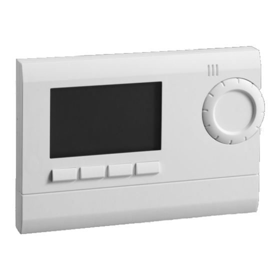
Opentherm room temperature controller with digital time switch. for vitodens 100-w, 111-w, 050-w
Hide thumbs
Also See for Vitotrol 100 OT:
- Installation & service instructions manual (12 pages) ,
- Operating instructions for the system user (16 pages)
Table of Contents
Advertisement
Advertisement
Table of Contents

Related Manuals for Viessmann Vitotrol 100 OT


Summary of Contents for Viessmann Vitotrol 100 OT
- Page 1 VIESMANN Installation and service instructions for contractors Room temperature controller OpenTherm room temperature controller with digital time switch For Vitodens 100-W, 111-W and 050-W Room temperature controller Please keep safe. 5837759 GB 12/2018...
-
Page 2: Safety Instructions
Safety instructions Safety instructions Please follow these safety instructions closely to prevent accidents and material losses. Safety instructions explained Danger Note This symbol warns against the Details identified by the word "Note" risk of injury. contain additional information. Please note This symbol warns against the risk of material losses and envi- ronmental pollution. - Page 3 ■ Isolate the system from the power system. supply, e.g. by removing the separate Replace faulty components only fuse or by means of a mains isolator, with genuine Viessmann spare and check that it is no longer live. parts. ■ Safeguard the system against recon- nection.
- Page 4 Safety instructions Safety instructions (cont.) Safety instructions for operating the system If you smell gas What to do if water escapes from the appliance Danger Escaping gas can lead to explo- Danger sions which may result in seri- If water escapes from the appli- ous injury.
- Page 5 Safety instructions Safety instructions (cont.) Danger Danger Leaking or blocked flue sys- The simultaneous operation of tems, or an inadequate supply the boiler and appliances that of combustion air can cause life exhausts air to the outside can threatening poisoning from car- result in life threatening poison- bon monoxide in the flue gas.
-
Page 6: Table Of Contents
Index Index Service instructions Information Disposal of packaging..................Symbols........................ Intended use......................Product information....................Installation instructions Preparing for installation Installation information..................10 Installation sequence Opening the controller..................11 Fitting the wall mounting base................11 Electrical connections................... 12 Assembling the controller..................14 Service instructions Commissioning and adjustment Starting up the room temperature controller............ -
Page 7: Information
Information Disposal of packaging Please dispose of packaging waste in line with statutory regulations. -
Page 8: Symbols
Information Symbols Sym- Meaning Reference to other document containing further information Step in a diagram: The numbers correspond to the order in which the steps are carried out. Warning of material losses and environmental pollution Live electrical area Pay particular attention. ■... -
Page 9: Intended Use
Information Intended use The appliance is intended solely for Any usage beyond this must be installation and operation in sealed approved by the manufacturer in each unvented heating systems that comply individual case. with EN 12828, with due attention paid to the associated installation, service Incorrect usage or operation of the and operating instructions. -
Page 10: Preparing For Installation
Preparing for installation Installation information Installation location for room temperature-dependent mode ■ On an internal wall in the main living Note on operation as a room temper- room, approx. 1.5 m above the floor ature controller ■ Not next to windows or doors Do not install further control devices in ■... -
Page 11: Installation Sequence
Installation sequence Opening the controller Fitting the wall mounting base... -
Page 12: Electrical Connections
Installation sequence Electrical connections Connection to the heat generator control unit 4 3 2 1 A Boiler control unit D Room temperature controller B Terminals on the control unit E Input for on-site switching contact C Outside temperature sensor F Remove jumper when connecting. Recommended connecting cable Please note ■... - Page 13 Installation sequence Electrical connections (cont.) On-site switching contact: Floating con- The following functions can be connec- tact, electrically isolated ted: ■ Window contact (operation with frost protection temperature when contact is open) ■ Telephone contact (telephone remote switch) ■ Presence detector (switching contact) Connection to mixer extension kit 4 3 2 1 1 2 3 4 5 6...
-
Page 14: Assembling The Controller
Installation sequence Electrical connections (cont.) H Jumper 1. Connect the heat generator control 2. Remove jumper H. unit and the room temperature con- troller. Connecting the on-site switching contact Connection at terminals 7 and 8 The following functions can be connec- On-site switching contact: Floating con- ted: tact, electrically isolated... -
Page 15: Commissioning And Adjustment
Commissioning and adjustment Starting up the room temperature controller Information on language setting 2. Change settings with +/- or the If a particular language is not available, rotary selector, and confirm with set the operating language to English. ■ Select the operating mode: Available languages: –... -
Page 16: Further Settings
Commissioning and adjustment Setting the mixer extension kit parameters (cont.) 04. Use 09. OK to confirm to select "SERVICE". 10. Set the required value with +/-. 05. OK to confirm 11. OK to confirm 06. Use to select "TSP-PARAM- ETER". 07. - Page 17 Commissioning and adjustment Further settings (cont.) Start optimisation Only for room temperature-dependent 1. Use to select "OPTIMISE". mode: The controller uses the differ- ence between the set and actual room 2. OK to confirm temperatures to determine how far in advance to set the central heating start 3.
- Page 18 Commissioning and adjustment Further settings (cont.) 4. OK to confirm 5. If possible, enter further settings and confirm with OK. Device type The factory setting for "DEVICE TYPE" 2. OK to confirm is "OPEN THERM". If this is not the case, set "OPEN THERM".
- Page 19 Commissioning and adjustment Further settings (cont.) -5 -10 -15 Outside temperature in °C Parameter Setting range Delivered condition 10 - 40 °C 25 °C Low end A 25 - 90 °C 60 °C End point B Shift 5 - 35 K 25 K The heating curve is limited at the "MAX TEMP"...
- Page 20 Commissioning and adjustment Further settings (cont.) Heating limit "HEATING OFF AT" adjustable from 15 - 25 °C Heating mode ends when the set out- Delivered condition - - side temperature ("HEATING OFF AT") is reached. Settings for room temperature-dependent mode ("ROOM-CON- TROL") Depending on the set and actual room Maximum flow temperature limit...
- Page 21 Commissioning and adjustment Further settings (cont.) 18.5 19.5 20.5 Actual room temperature in °C A P 1.0 K B P 2.0 K C P 1.6 K (factory setting) Setting the I component time ■ If the actual room temperature is < the set room temperature and the With the "I-TERM"...
- Page 22 Commissioning and adjustment Further settings (cont.) Soft start The "SOFT START" function is not active. Emissions test function The "CHIMNEY SWEEP" function is not active.
-
Page 23: Troubleshooting
Troubleshooting Fault messages If a fault occurs, the display shows "ERROR". Press INFO to show the fault message. Fault message Meaning "ERROR OUTSIDE TEMPER- Short circuit/lead break, outside temperature sen- ATURE" "ERROR - FLAME" No flame signal "ERROR - WATER TEMP" Temperature limiter has responded Note For messages "ERROR D0"... - Page 24 Troubleshooting Scanning temperatures and programs (cont.) Scan Meaning "BURNER STARTS/10" Displayed value multiplied by 10 gives the number of burner starts performed (not shown if connected to mixer extension kit) "BURNER HOURS/10" Displayed value multiplied by 10 gives the number of burner hours run (not shown if connected to mix- er extension kit)
-
Page 25: Specification
Specification Specification Power supply Via OpenTherm IP rating IP 20 to EN 60529 Protection class II to EN 60730-1 subject to correct installation Power reserve Accuracy ≤ 1 s/day at 20 °C... - Page 28 Viessmann Werke GmbH & Co. KG Viessmann Limited D-35107 Allendorf Hortonwood 30, Telford Telephone: +49 6452 70-0 Shropshire, TF1 7YP, GB Fax: +49 6452 70-2780 Telephone: +44 1952 675000 www.viessmann.com Fax: +44 1952 675040 E-mail: info-uk@viessmann.com...