MULTIQUIP MAYCO Series Operation Manual
Concrete pump
Hide thumbs
Also See for MAYCO Series:
- Operation and parts manual (148 pages) ,
- Operation manual (94 pages) ,
- Operation manual (90 pages)
Table of Contents
Advertisement
Quick Links
Advertisement
Table of Contents
Troubleshooting

Related Manuals for MULTIQUIP MAYCO Series


Summary of Contents for MULTIQUIP MAYCO Series
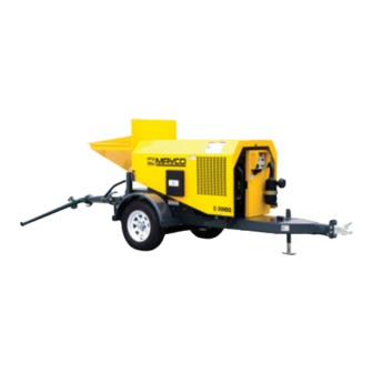
- Page 1 OPERATION MANUAL SERIES MODEL C30HDGA CONCRETE PUMP (ZENITH 416 GAMMA GASOLINE ENGINE) Revision #1 (09/09/19) To find the latest revision of this publication or associated parts manual, visit our website at: www.multiquip.com THIS MANUAL MUST ACCOMPANY THE EQUIPMENT AT ALL TIMES.
-
Page 2: Proposition 65 Warning
PROPOSITION 65 WARNING PAGE 2 — MAYCO C30HDGA CONCRETE PUMP • OPERATION MANUAL — REV. #1 (09/09/19) -
Page 3: Silicosis/Respiratory Warnings
SILICOSIS/RESPIRATORY WARNINGS WARNING WARNING SILICOSIS WARNING RESPIRATORY HAZARDS Grinding/cutting/drilling of masonry, concrete, metal and Grinding/cutting/drilling of masonry, concrete, metal and other materials with silica in their composition may give other materials can generate dust, mists and fumes off dust or mists containing crystalline silica. Silica is a containing chemicals known to cause serious or fatal basic component of sand, quartz, brick clay, granite and injury or illness, such as respiratory disease, cancer,... -
Page 4: Table Of Contents
TABLE OF CONTENTS C30HDGA Concrete Pump Proposition 65 Warning ........... 2 Silicosis/Respiratory Warnings ........ 3 Safety Information ..........5–10 Specifications ............11 Dimensions ............12 Important Hand Signals ......... 13 General Information ......... 14–16 Components (Pump) ........18–19 Components (Control Box) ........20 Components (Engine) .......... -
Page 5: Safety Information
SAFETY INFORMATION Do not operate or service the equipment before reading Potential hazards associated with the operation of this the entire manual. Safety precautions should be followed equipment will be referenced with hazard symbols which at all times when operating this equipment. may appear throughout this manual in conjunction with Failure to read and understand the safety safety messages. - Page 6 „ NEVER use accessories or attachments that are not Disconnection of these devices can cause severe injury, recommended by Multiquip for this equipment. Damage bodily harm or even death. Disconnection of any of to the equipment and/or injury to user may result.
- Page 7 „ Multiquip strongly encourages the operator to take the safety training courses offered by the American Concrete Pumping Association (www.concretepumpers.com). MAYCO C30HDGA CONCRETE PUMP • OPERATION MANUAL — REV. #1 (09/09/19) — PAGE 7...
- Page 8 SAFETY INFORMATION BATTERY SAFETY NOTICE „ NEVER run engine without an air fi lter or with a dirty air DANGER fi lter. Severe engine damage may occur. Service air fi lter „ DO NOT drop the battery. There is a possibility that the frequently to prevent engine malfunction.
- Page 9 SAFETY INFORMATION TRANSPORTING SAFETY „ Check the tire air pressure on both towing vehicle and trailer. Trailer tires should be infl ated to 80 psi cold. CAUTION Also check the tire tread wear on both vehicles. „ NEVER allow any person or animal to stand underneath „...
- Page 10 SAFETY INFORMATION ENVIRONMENTAL SAFETY/DECOMMISSIONING EMISSIONS INFORMATION NOTICE NOTICE Decommissioning is a controlled process used to safely The diesel engine used in this equipment has been retire a piece of equipment that is no longer serviceable. designed to reduce harmful levels of carbon monoxide If the equipment poses an unacceptable and unrepairable (CO), hydrocarbons (HC) and nitrogen oxides (NOx) safety risk due to wear or damage, or is no longer cost...
-
Page 11: Specifications
SPECIFICATIONS Table 1. C30HDGA Pump Specifications Pump Type Reciprocating Piston Pumping Rate Up to 25 cu. yds. per hour* Vertical Pumping Height Up to 150 ft. (45.73 m) Horizontal Pumping Distance 400 - 500 ft. (122 - 152 m)* Max. Concrete Piston Face Pressure 500 PSI Maximum Aggregate Size 1/2 in. -
Page 12: Dimensions
DIMENSIONS MAYC0 C-30HDGA 145 IN. (3.68 M) DISCHARGE CONE IN TRAVEL POSITION Table 3. Pump Dimensions Reference Dimensions Letter in. (mm) 76 (1930) 14.5 (368) 16 (406) 161 (4089) 63.5 (1612) 59.5 (1511) PAGE 12 — MAYCO C30HDGA CONCRETE PUMP • OPERATION MANUAL — REV. #1 (09/09/19) -
Page 13: Important Hand Signals
IMPORTANT HAND SIGNALS STOP START PUMP SLOW PUMP CHUTE UP CHUTE DOWN SPEED UP DOWN ADD WATER ALL DONE STOP PUMP LITTLE BIT CLEAN-UP 4-GALLONS PULL FORWARD BACK IN DRIVE IN BACK UP Figure 1. Operation Hand Signals MAYCO C30HDGA CONCRETE PUMP • OPERATION MANUAL — REV. #1 (09/09/19) — PAGE 13... -
Page 14: General Information
GENERAL INFORMATION The following operating principles and operating suggestions As a general rule, the use of approximately six sacks of should prove helpful in the successful operation of your cement, 70% washed concrete sand and 30% #4 pea gravel concrete pump. Your new “small line” concrete pump has per yard of concrete will result in a pumpable mix. - Page 15 GENERAL INFORMATION HOW IT WORKS An automatic, centrifugal clutch is installed to engage and disengage the pumping action without stopping or starting The C30HDGA concrete pump has one main pumping the engine. The centrifugal clutch is set at 1100 R.P.M. The piston which is valved by means of two ball checks.
-
Page 16: General Information
GENERAL INFORMATION The pumping piston (Figure 3) is forcing the material past The return spring is installed to eliminate shock and stress ball (B) and out to the nozzle, also seating ball A so that the between the cam roller and the cam weldment when material will not flow back to the hopper. - Page 17 NOTES MAYCO C30HDGA CONCRETE PUMP • OPERATION MANUAL — REV. #1 (09/09/19) — PAGE 17...
-
Page 18: Components (Pump)
COMPONENTS (PUMP) Figure 5. Pump Components PAGE 18 — MAYCO C30HDGA CONCRETE PUMP • OPERATION MANUAL — REV. #1 (09/09/19) -
Page 19: Components (Pump)
COMPONENTS (PUMP) Figure 5 illustrates the location of the major components 12. Tow End Jack Stand — Use this jack stand to level and support the pump. for the C30HDGA Concrete Pump. The function of each component is described below: 13. -
Page 20: Components (Control Box)
COMPONENTS (CONTROL BOX) Figure 6. Pump Control Box Components Figure 6 illustrates the location of the major components 4. Remote Control Input Connector — Insert the for the C30HDGA Control Box. The function of each remote control input cable into this connector. component is described below: 5. -
Page 21: Components (Engine)
COMPONENTS (ENGINE) Figure 7. Zenith 416 Gamma Engine Components Figure 7 illustrates the location of the basic components 7. Oil Filter — Replace this oil filter as recommended in for the Zenith 416 Gamma gasoline engine. The function the maintenance section of this manual. of each component is described below: 8. -
Page 22: Inspection
INSPECTION FUEL CHECK WARNING DANGER NEVER operate the pump in a confined area or enclosed area structure that Handle fuel safely. Motor fuels are highly flammable does not provide ample free flow of air. and can be dangerous if mishandled. NEVER smoke while refueling. - Page 23 INSPECTION LUBRICATION BOX The C30HDGA features a fully enclosed lubrication box, which utilizes the "SPLASH" method of lubrication. Before using your new pump, 7 gallons of SAE 30 motor oil must be added directly into the lubrication box. Visually inspect the oil in the lubrication box by making sure the oil is at the correct operating level as indicated by the dip stick (Figure 11).
-
Page 24: Inspection
INSPECTION CHECKING ENGINE COOLANT LEVEL V-BELT 1. Remove the radiator cap, and check the cooling water 1. Inspect the V-belt (Figure 14) to determine if it is frayed, level inside the radiator (Figure 13). peeling, full of tiny cracks, has pieces of rubber missing, or is otherwise damaged. -
Page 25: Startup/Shutdown
STARTUP/SHUTDOWN STARTING PROCEDURE 4. Let the engine run for 3-5 minutes before putting pump into operational use. WARNING 5. Listen for any abnormal sounds. If any mechanical DO NOT attempt to operate this concrete pump until or electrical problems exists, STOP the engine and the Safety Information, General Information, and correct the problem. -
Page 26: Operation
OPERATION OPERATING SUGGESTIONS c. It is necessary to wait 10 minutes or more for another load of concrete, it is wise to start the 1. A well-planned location of the pump and routing of pump and pump 6 or 8 strokes every 5 minutes to the hose before starting a pour may save subsequent prevent setting of the mix in the system. - Page 27 OPERATION Concrete starts setting by drying up through a chemical WARNING reaction. The catalyst to this reaction is heat. When If you repeatedly increase speed and try to force your pumping a hot load, it is important to remember that pump to push through blockages due to separation of when you have to stop pumping for any reason, add material in the hose or manifold, you will soon have...
- Page 28 OPERATION 3. When pumping long distance or pumping stiff mixes, at least 20 feet away from the pump and turn their you can expect a drop in volume compared to shorter heads away from the manifold. lines and wetter mixes due to the change in valve d.
- Page 29 OPERATION 1. Disconnect the hoses from the pump and wash the Use a 25 ft. hose, or short section, off the pump; and for the pump out immediately. For example: If you had 200 ft. balance of the horizontal distance to the vertical line, use of system out, you would disconnect each hose.
- Page 30 OPERATION PULSATION 2. On the control box, place the pumping control switch in the REMOTE ON position (Figure 21) A slight pulsation of the hose will always be noticeable near the pump. Excessive pulsation of the hose near the pump is normally due to higher than average line pressures caused by stiff, harsh mixes, or extremely long pumping distances.
-
Page 31: Maintenance
MAINTENANCE PREVENTIVE MAINTENANCE 5. It is important that the hinged discharge cone on the pump manifold be opened and all remaining concrete It is extremely important to maintain this pump due to the (rock and sand) be thoroughly washed out. This must highly abrasive nature of concrete material. - Page 32 MAINTENANCE 5. Take a sponge (2”x 4”x 6”) and soak it with water. Take NOTICE the hose that is disconnected from the pump and shake IMPORTANT! To ensure maximum cup life, the oil level out the concrete so that about 2 feet of it is clear. Insert in the lubrication box must be maintained at the proper the sponge into the hose.
- Page 33 MAINTENANCE flange and in the leading edge of the manifold. Put the NOTICE manifold onto the primary side of the pump and install Make sure the eccentric lock is facing toward the bolts leaving them loose. outside of the pumping unit. 7.
- Page 34 MAINTENANCE BEARING INSTALLATION 1. Install the bearing components on the crankshaft making full contact with the back side of the crank disc as indicated the symbol #. See Figure 23 below. 2. Install the bushing in the cam weldment and slide it onto the crankshaft until contact is made with the bearing spacer.
- Page 35 MAINTENANCE DETENT HOLE (3) INSTALLATION 3. If this procedure is not followed closely the heavy loading of the bearing during pumping operation 1. After the bearing assembly has been is installed , causes the Timken™ cone bearings to create lateral remove the three “dog type”...
- Page 36 MAINTENANCE V-BELT AND DRIVE CHAIN ADJUSTMENT 6. Lubricate the chain regularly. It is advisable to carry a spare chain and master links for replacement in the 1. Loosen the pillow bearing bolts (Figure 25) only to the field if necessary. point where the bolts will remain snug.
- Page 37 MAINTENANCE INSTALLATION AND DRIVE ALIGNMENT A properly selected, installed and maintained drive chain (Figure 26) is an extremely versatile means of power Chain and sprockets (Figure 27) must be installed transmission. It is possible, however, to greatly reduce a correctly. Sprockets must be properly aligned and sprocket chain’s life and even induce failure if the chain is abused shafts must be parallel so the drive will run in a plane through improper installation, operating or maintenance...
- Page 38 MAINTENANCE DRIVE CHAIN LUBRICATION The clearance between pin and bushings is very small (Figure 29), on the order of .003 to .005 inches. A lubricant As a chain articulates in entering and leaving a sprocket, must be thin enough to flow into the chain. SAE 30 weight there is relative movement between pin and bushing oil is about right for room temperature.
- Page 39 MAINTENANCE ASSEMBLING AND DISASSEMBLING DRIVE CHAIN NOTICE CAUTION Modified and Full Press Fits require some patience and tools to assemble and/or disassemble. Use vice grips, You may be seriously injured if you attempt to install plumbers pliers or a small hammer to drive coversides the drive chain while the pump is running.
-
Page 40: Trailer Maintenance
TRAILER MAINTENANCE ADJUSTABLE CHANNEL If the trailer has not been used for an extended amount of time, have the bearings inspected and packed more Your trailer may be equipped with an adjustable channel frequently, at least every six months and prior to use. (Figure 30) that allows the coupler to be raised or lowered Follow the steps below to disassemble the wheel hub and to a desired height. - Page 41 TRAILER MAINTENANCE TORSION SUSPENSION DANGER The mounting bracket and associated components NEVER crawl under the trailer unless it is on firm (Figure 32) should be visually inspected every 6,000 and level ground and resting on properly placed and miles for signs of excessive wear, elongation of bolt secured jackstands.
-
Page 42: Trailer Guidelines
TRAILER GUIDELINES The following guidelines are intended to assist the operator „ DO NOT ride the brakes while descending grades, they in the operation and handling of a trailer. may get so hot that they stop working. Then you will potentially have a runaway tow vehicle and trailer. - Page 43 TRAILER GUIDELINES DRIVING CONDITIONS WARNING When towing a trailer, you will have decreased acceleration, Proper selection and condition of the coupler and hitch increased stopping distance, and increased turning radius are essential to safely towing your trailer. A loss of (which means you must make wider turns to keep from coupling may result in death or serious injury.
- Page 44 TRAILER GUIDELINES INOPERABLE LIGHTS OR MIRRORS Drive slowly at fi rst, 5 mph or so, and turn the wheel to get the feel of how the tow vehicle and trailer combination Be sure that all of the lights on your trailer are functioning responds.
- Page 45 TRAILER GUIDELINES ELECTRICAL CONNECTOR GVWR: The maximum allowable gross weight of the trailer and its contents. The gross weight of the trailer includes An Electrical Connector connects the lights on the trailer the weight of the trailer and all of the items within it. GVWR to the lights on the towing vehicle.
- Page 46 TRAILER GUIDELINES A ball hitch trailer may be fi tted with a tongue jack that can THE TOW VEHICLE, HITCH AND BALL MUST HAVE A raise and lower the coupler. The tongue jack is mounted to RATED TOWING CAPACITY EQUAL TO OR GREATER THAN THE TRAILER Gross Vehicle Weight Rating the A-frame (front or tongue) part of the trailer.
- Page 47 TRAILER GUIDELINES Coupling the Trailer to the Tow Vehicle (Ball Coupler) NOTICE „ Lubricate the hitch ball and the inside of the coupler with Overloading can damage the tongue jack. DO NOT a thin layer of automotive bearing grease. use the tongue jack to raise the tow vehicle more than one inch.
- Page 48 TRAILER GUIDELINES Connecting Trailer Lights ” Connect the trailer lights to the tow vehicle’s electrical system using the electric connectors at the front of the trailer (tongue). Refer to the wiring diagram shown in the trailer wiring diagram section of this manual. Before towing the trailer check for the following: „...
- Page 49 TRAILER GUIDELINES THE TOW VEHICLE, PINTLE HITCH AND PINTLE WARNING COUPLER MUST HAVE A RATED TOWING CAPACITY A defective pintle hitch not properly fastened can result EQUAL TO OR GREATER THAN THE TRAILER Gross in uncoupling, leading to death or serious injury. Vehicle Weight Rating (GVWR).
- Page 50 TRAILER GUIDELINES TIRE SAFETY Lug nuts are also prone to loosen after first being assembled. When driving a new trailer (or after wheels Unsafe Tires, Lug Nuts or Wheels have been remounted), check to make sure they are tight after the fi rst 10, 25 and 50 miles of driving and before Trailer tires and wheels are more likely to fail than car tires each tow thereafter.
- Page 51 TRAILER GUIDELINES TIRE FUNDAMENTALS Speed Rating: The speed rating denotes the speed at which a tire is designed to be driven for extended periods Federal law requires tire manufacturers to place standardized of time. The ratings range from 99 miles per hour (mph) to information on the sidewall of all tires (Figure G).
- Page 52 TRAILER GUIDELINES Uniform Tire Quality Grading Standards (UTQGS) Load Range: This information identifi es the tire’s load- carrying capabilities and its infl ation limits. Treadwear Number: This number indicates the tire’s Tire Safety Tips wear rate. The higher the treadwear number is, the longer it should take for the tread to wear down.
- Page 53 TRAILER GUIDELINES Wheels, Bearings and Lug Nuts Table B below will help pinpoint the causes and solutions of tire wear problems. Check wheel bearings, jack trailer and check wheels for side-to-side looseness. If the wheels are loose, or spin Table B. Tire Wear Troubleshooting with a wobble, the bearings must be serviced or replaced.
- Page 54 TRAILER GUIDELINES Lights and Signals Before each tow, check the trailer taillights, stoplights, turn signals and any clearance lights for proper operation. Replace any broken or burned-out lamps as necessary. Check the wire harness for cuts, fraying or other damage. If it needs replacing, contact your dealer.
-
Page 55: Trailer Guidelines
TRAILER GUIDELINES Figure J. Trailer to Tow Vehicle Wiring Diagram MAYCO C30HDGA CONCRETE PUMP • OPERATION MANUAL — REV. #1 (09/09/19) — PAGE 55... -
Page 56: Troubleshooting
TROUBLESHOOTING Table 5. Troubleshooting (Pump) Symptom Possible Problem Solution Delivery system is plugged. Clear obstruction from Material pressure build up in manifold manifold and/or delivery system Worn clutch friction lining or damaged Replace clutch lining or rotor springs Clutch slipping Manifold is packing with material, incorrect Verify correct mix ratio mix ratio... -
Page 57: Troubleshooting
TROUBLESHOOTING Table 6. Troubleshooting (Diesel Engine) Symptom Possible Problem Solution No Fuel reaching injection pump? Add fuel. Check entire fuel system. Defective fuel pump? Replace fuel pump. Fuel filter clogged? Replace fuel filter and clean tank. Faulty fuel supply line? Replace or repair fuel line. -
Page 58: Engine Fault Codes
ENGINE FAULT CODES MALFUNCTION INDICATOR DIAGNOSTIC SYSTEM 4. If the check engine warning lamp is on, stop engine. Place ignition key in the OFF position. See Figure 35. The C30HDGA concrete pump features an engine malfunction indicator lamp found on the control box (Figure 34). - Page 59 ENGINE FAULT CODES 7. Close hood and place ignition key in the ON position. 9. The check engine warning lamp will flash in 3 separate See Figure 37. bursts as shown below. This sequence of lamp flashing represents the MIL flash error code (Figure 39). See Table 7 for a complete listing of error codes.
- Page 60 ENGINE FAULT CODES Table 7. GCP ECU Fault Code List for ZPP 416 Engine FAULT DESCRIPTION TURNS ON MIL? MIL FLASH CODE Leader/Trailer Code Lockoff open / ground short Lockoff short to power CRANK or CAM could not synchronize during start MAP signal low or shorted to ground MAP signal high IAT signal Low/Shorted to GND...
- Page 61 ENGINE FAULT CODES Table 7. GCP ECU Fault Code List for ZPP 416 Engine (continued) FAULT DESCRIPTION TURNS ON MIL? MIL FLASH CODE Injector 2 Low/Open Injector 2 High/Short Injector 3 Low/Open Injector 3 High/Short Injector 4 Low/Open Injector 4 High/Short Injector 5 Low/Open Injector 5 High/Short Injector 6 Low/Open...
- Page 62 ENGINE FAULT CODES ENGINE FAULT CODES Table 7. GCP ECU Fault Code List for ZPP 416 Engine (continued) FAULT DESCRIPTION TURNS ON MIL? MIL FLASH CODE Gasoline fuel pump relay control wire short to 12 V Pin 85 (AUX_PWM4) open/short to GND 5V Reference #1 voltage low 5V reference #1 voltage high MIL control ground short...
-
Page 63: Engine Fault Codes
ENGINE FAULT CODES Table 7. GCP ECU Fault Code List for ZPP 416 Engine (continued) FAULT DESCRIPTION TURNS ON MIL? MIL FLASH CODE AUX 5V ANALOG INPUT 3 open or high AUX 5V ANALOG INPUT 3 low AUX 5V ANALOG INPUT 1 high / Low Coolant Shutdown (On units Equipped) AUX 5V ANALOG INPUT 1 low or open AUX 5V ANALOG INPUT 2 high or open... -
Page 64: Appendix - Concrete Mix Information
APPENDIX — CONCRETE MIX INFORMATION CONCRETE MIX INFORMATION The following information has been extracted from actual testing laboratory reports. The purpose of this printing is only to help create a better understanding of the importance of uniform gradation and proportioning of materials which affect pumpability of concrete mixes. - Page 65 APPENDIX — CONCRETE MIX INFORMATION A.S.T.M. STANDARD SPECIFICATION FOR GRADING AGGREGATE MAYCO C30HDGA CONCRETE PUMP • OPERATION MANUAL — REV. #1 (09/09/19) — PAGE 65...
-
Page 66: Appendix — Concrete Mix Information
APPENDIX — CONCRETE MIX INFORMATION SLUMP TEST PROCEDURE BULLET POINTED 1. To obtain a representative sample (concrete), take STEEL ROD several samples at three or more regular intervals throughout the discharge of the mixer or truck. DO NOT take samples at the beginning or end of the discharge. 2. -
Page 67: Wiring Diagram (Wiring Harness)
WIRING DIAGRAM (WIRING HARNESS) TERMINAL BLOCK 16 AWG RED +12 VDC EMERGENCY STOP PUSHBUTTON IGNITION SWITCH HOUR METER +12 VDC 16 AWG BLU 16 AWG RED PUMPING CONTROL SWITCH REMOTE CONTROL OPEN = PUMPING 16 AWG RED CLOSED = IDLE REMOTE CONNECTOR 16 AWG... -
Page 68: Electrical Component Locator
ELECTRICAL COMPONENT LOCATOR CONTROL PANEL REAR VIEW PUMP HOOD NOT SHOWN FOR CLARITY PAGE 68 — MAYCO C30HDGA CONCRETE PUMP • OPERATION MANUAL — REV. #1 (09/09/19) -
Page 69: Electrical Component Locator
ELECTRICAL COMPONENT LOCATOR MAYCO C30HDGA CONCRETE PUMP • OPERATION MANUAL — REV. #1 (09/09/19) — PAGE 69... - Page 70 © COPYRIGHT 2019, MULTIQUIP INC. Multiquip Inc , the MQ logo and the Mayco logo are registered trademarks of Multiquip Inc. and may not be used, reproduced, or altered without written permission. All other trademarks are the property of their respective owners and used with permission.