Table of Contents
Advertisement
Advertisement
Table of Contents

Related Manuals for Stoelting E157


Summary of Contents for Stoelting E157
- Page 1 Model E157/E257/F257 Owner's Manual Manual No. 513563 Jul. 2003, Rev. 2...
- Page 3 Need Parts or Service? We stock the parts you need. Our Technicians are factory trained and are certified in the Stoelting Technicare program. CALL Distributor: _________________________ Phone No.: _________________________ Model No.: _______________________ Serial No.: _______________________ Purchase Date: ____________________ Start-Up Date:____________________...
- Page 5 DO NOT ATTEMPT to operate the freezer until instructions and safety precautions in the manual are read completely and thoroughly understood. The freezer should be operated by only qualified personnel. If problems develop or arise in connection with installation, operation or servicing of the freezer, contact your local Stoelting Distributor. Stoelting, LLC 502 Hwy. 67...
-
Page 7: Table Of Contents
3.12 Extended Storage ... 18 SECTION 4 - REPLACEMENT PARTS & REFERENCE DRAWINGS ... 21 4.1 How to Order Decals and Tags ... 21 4.2 Exploded Views and Parts Lists (E157, E257, F257) ... 22 ADDENDUM - FILL-O-MATIC ... 29... - Page 8 Model E157 - Side ... Model E257/F257 - Front ... Model E257/F257 - Side ... Adjustable Leg ... Warning Label Locations - E157 ... Warning Label Locations - E257/F257 ... Space & Ventilation Requirements ... Electrical Plug ... Installing Sani-tray and Cover ...
-
Page 9: Section 1 - Introduction
1.1 DESCRIPTION Models E157/E257F257 freezers are gravity fed. The freezers are equipped with fully automatic controls to provide a uniform product. The freezers are designed to operate with most neutral bases and concentrated flavors. 1.2 SPECIFICATIONS E157 COUNTER MODEL FREEZER width: 15"... -
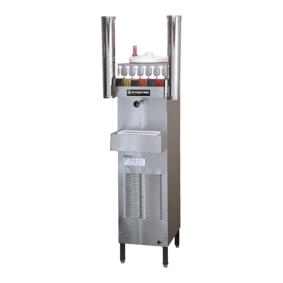
Page 10: Model E157 - Front
Figure 1 Model E157 - Front Figure 3 Model E257/F257 - Front NOTE: Figures in parenthesis are in centimeters. Figure 2 Model E157 - Side Figure 4 Model E257/F257 - Side... -
Page 11: Section 2 - Installation Instructions
2.1 SAFETY PRECAUTIONS Do not attempt to operate the freezer until the safety precautions and operating instructions in this manual are read and completely understood. Take notice of all warning labels on the freezer (Figures 6 & 7). The labels have been put there to help maintain a safe working environment. -
Page 12: Warning Label Locations - E157
DANGER ELECTRONIC SHOCK HAZARD DISCONNECT FROM THE SOUCE OF ELECTRICAL SUPPLY IN BUILDING BEFORE SERICING UNIT 321105 723529 Figure 6 Warning Label Locations - E157 CAUTION THIS DEVICE MUST BE PLUGGED INTO A GROUNDED RECEPTACLE TO PREVENT SHOCK HAZARD. 324113... -
Page 13: Warning Label Locations - E257/F257
IMPORTANT NOTICE TO OPERATOR BEFORE INSTALLING EQUIPMENT, READ THE OWNER'S MANUAL CAREFULLY. TAKE NOTE OF ALL INSTRUCTIONS AND CAUTION DECALS ON THIS EQUIPMENT. GO OVER THE MANUAL THOROUGHLY AND POINT OUT ALL DECALS TO YOUR EMPLOYEES, SO THEY UNDERSTAND HOW TO SAFELY OPERATE THIS EQUIPMENT. -
Page 14: Space & Ventilation Requirements
D. The floor model freezers are equipped with air-cooled condensers and require correct ventilation. The front of the freezer is the air intake and must be unobstructed. Air discharges out of the rear of the unit. Do not obstruct the discharge. Allow a 6" (15.2 cm) clearance behind the unit (Fig. -
Page 15: Adjusting Cup Dispensers
2.4 ADJUSTING CUP DISPENSERS To adjust the cup dispensers, install the size cup desired into the dispenser and turn the wing nuts on the dispenser mounting bracket until enough tension is applied to the rim of the cup to keep it from dropping out (Fig. 11). Do not over- tighten the wing nuts. -
Page 17: Section 3 - Initial Set-Up And Operation
3.1 OPERATOR'S SAFETY PRECAUTIONS A. Know the freezer. Read and understand the Operating Instructions. B. Notice all warning labels on the freezer. C. Wear proper clothing. Avoid loose fitting garments, and remove watches, rings or jewelry which could cause a serious accident. D. -
Page 18: Draining The Freezer For Disassembling And Cleaning
A. STIRRING ONLY-OFF-STIRRING & FREEZING SWITCH The STIRRING ONLY-OFF-STIRRING & FREEZ- ING switch is a three-position toggle switch used to control the operation of the refrigeration system and agitator. When the switch is placed in the STIR- RING ONLY position, the refrigeration system will be off and the agitator will rotate for cleaning, or if stirring is required when the store is closed. -
Page 19: Removing Sani-Tray And Cover
Figure 13 Removing Drip Tray and Cover Figure 14 Draining Product Inspection for worn or broken parts should be made during every disassembly of the freezer for cleaning or other purposes. All worn or broken parts should be replaced to ensure safety to both the operator and the customer, and to maintain good freezer performance as well as a quality product. -
Page 20: Removing Spigot Assembly
Figure 15 Removing Spigot Assembly O-RING #624607 SPLASH DEFLECTOR* #1120918 SHAFT & PLUG ASSEMBLY #1147688 Cut-away View of Spigot Assembly Figure 16 Removing Spigot O-Ring from Spigot body SPRING #694400 RETAINER CAP #232002 *Note: End of splash deflector with larger opening faces the spring. -
Page 21: Removing Drive Cap And O-Ring
1. With a clean, dry towel, wipe excess lubricant from the spigot assembly and o-ring. Firmly grasp the spigot assembly with both hands and squeeze the o-ring upward (Fig 16). When a loop is formed, roll the o-ring out of the groove toward the end of the spigot assembly. (See Fig. -
Page 22: Removing Divider Plate From Agitator Fingers
5. Unscrew the divider plate from the agitator fingers and remove (Fig.21). Figure 21 Removing Divider Plate from Agitator Fingers 6. Remove the drive shaft by pulling straight up and out of the vertical center post (Fig.22). Figure 22 Removing Drive Shaft Figure 23 Exploded View of Divider Plate and Agitator Assembly... -
Page 23: Sanitizing The Freezers And Freezer Parts
3.5 SANITIZING THE FREEZER AND FREEZER PARTS After the freezer parts have been soaked and washed in warm, soapy water, they should be rinsed thoroughly in clean water. All parts must be sanitized before assembling with a USDA certified food grade sanitizing solution (50 parts per million of free available chlorine or equivalent is accept- able). -
Page 24: Installing Divider Plate And Agitator Assembly
2. Install the drive shaft into the center post by rotating and pressing down lightly on the shaft until the shaft drops down and engages with the gear box shaft. 3. Replace the plastic lower bushing to the bottom of the vertical center post. -
Page 25: Mix Information
B. Assemble O-rings onto the spigot plungers without lubricant. Then apply a thin film of sanitary lubricant to the exposed surfaces of the O-rings. 1. Insert the spigot assembly into the product outlet. 2. Slide the spigot retaining clip into position. C. -
Page 26: Extended Storage
A. DAILY 1. The exterior should be kept clean at all times to preserve the lustre of the stainless steel. A mild alkaline cleanser is recommended. Use a soft cloth or sponge to apply the cleanser. CAUTION DO NOT USE ACID CLEANERS, STRONG CAUSTIC COMPOUNDS OR ABRASIVE MATERIALS TO CLEAN ANY PART OF THE FREEZER EXTERIOR OR PLASTIC PARTS. -
Page 27: External Parts To Be Cleaned
CUP DISPENSERS AND LIDS COVERS LIQUID LEVEL INDICATOR FLAVOR BOTTLES DRIP TRAY SUPPORT, DRIP TRAY, DRIP TRAY GRID ALL PANELS Figure 28 External Parts To Be Cleaned... -
Page 29: Section 4 - Replacement Parts & Reference Drawings
DECAL MANUAL RESET 324393 DECAL STOELTING SWIRL 324548 DECAL ADEQUATE VENTILATION - E257/F257 Floor Model 324585 DECAL REFRIGERATION CHARGE 324649 DECAL ADEQUATE VENTILATION - E157 - Counter Model 723516 TAG ATTN: SET TIMER 723526 TAG READ MANUAL 723529 TAG CAUTION 723537... -
Page 30: Exploded Views And Parts Lists (E157, E257, F257)
4.2 Explosed Views and Parts Lists Model E157 Exploded View... - Page 31 Model E157 Parts List...
- Page 32 Model E257 Exploded View...
- Page 33 Model E257 Parts List...
- Page 34 Model F257 Exploded View...
- Page 35 Model F257 Parts List...
-
Page 37: Addendum Fill-O-Matic
The Fill-O-Matic is a transfer pump designed to keep the freezer full of product. A. Pump Hose Removal WARNING DISCONNECT THE FREEZER FROM ELECTRI- CAL SUPPLY SOURCE BEFORE SERVICING! 1. Remove the two phillips head screws from the rear panel and pull the rear panel down and out. 2. - Page 39 PLIED WARRANTY OF MERCHANTABILITY OR FITNESS FOR PARTICULAR PURPOSE. 3. Remedies: Stoelting’s sole obligations, and Buyer’s sole remedies, for any breach of this warranty shall be the repair or (at Stoelting’s option) replacement of the affected component at Stoelting’s plant in Kiel, Wisconsin, or (again, at Stoelting’s option) refund of the purchase price of the affected equipment, and, during the first ninety (90) days of...