
Related Manuals for Contec CONPROSYS nano CPSN-MCB271-S1-041


Summary of Contents for Contec CONPROSYS nano CPSN-MCB271-S1-041
- Page 1 CONPROSYS nano Remote I/O CPU Unit CPSN-MCB271-S1-041 Reference Manual (Hardware) CONTEC CO., LTD.
- Page 2 Check Your Package Thank you for purchasing the CONTEC product. This product consists of the items listed below. Check, with the following list, that your package is complete. If you discover damaged or missing items, contact your retailer. Product Configuration List - Product [CPSN-MCB271-S1-041]…1...
-
Page 3: Copyright
No part of this document may be copied or reproduced in any form by any means without prior written consent of CONTEC CO., LTD. CONTEC CO., LTD. makes no commitment to update or keep current the information contained in this document. -
Page 4: Table Of Contents
Table of Contents Check Your Package ..........................i Copyright ............................ii Trademarks ............................ii Table of Contents ..........................iii Before Using the Product About the Unit ............................. 1 Hardware Features........................1 Software Features ......................... 2 How to use............................ 2 Model details ..........................3 Customer Support.......................... - Page 5 Push Switch (SW) ........................33 USB Port (USB) ......................... 33 LAN Port (LAN) ........................34 Expansion slot ..........................35 microSD Card Slot ........................35 System Reference Specifications ............................ 37 Power Requirements........................38 Physical Dimensions ........................39 List of Optional Products DIN rail fitting power supply .....................
-
Page 6: Before Using The Product
1 Before Using the Product 1. Before Using the Product This chapter provides necessary information before using the product. About the Unit This product is a remote I/O model CPU unit that has RS-232C and LAN interfaces in addition to four expansion slots. -
Page 7: Software Features
(standard COM). Applications can be created with the OS standard Win32 API communication function. How to use Information regarding how to use this product is given in the CPSN-MCB271 Reference Manual (Software), so check the System Setup Guide from the CONTEC website. The name of the documents Contents How to get... -
Page 8: Model Details
1 Before Using the Product Model details CPSN - MCB 2 7 1 - S 1 - 0 4 1 CONPROSYS nano Series Item Contents MCB: Standard Backplane Model Model 2: ARM Cortex M3 Memory 7: 16M Byte Version 1: The 1 Model S: Serial (RS-232C/RS-422/485) Interface... -
Page 9: Customer Support
You can download updated driver software and differential files as well as sample programs in several languages. Note: For product information Contact your retailer if you have any technical questions regarding a CONTEC product or need its price, delivery time, or estimate information. Limited Two-Year Warranty CONTEC products are warranted by CONTEC CO., LTD. -
Page 10: Safety Precautions
1 Before Using the Product Safety Precautions Understand the following definitions and precautions to use the product safely. Safety Information This document provides safety information using the following symbols to prevent accidents resulting in injury or death and the destruction of equipment and resources. Understand the meanings of these labels to operate the equipment safely. -
Page 11: Handling Precautions
1 Before Using the Product Handling Precautions DANGER Do not use the product in locations exposed to a flammable or corrosive gas. It may cause explosion, fire, electrical shock, or malfunction. Do not allow the device to come into contact with foreign substances (metal particles, flammable substances, liquids, etc.) Otherwise, it can cause fire or electrical shock. - Page 12 When removing connectors or cables, always unplug the power cable of CPU unit and confirm the LEDs are turned off. Do not modify the product. CONTEC will bear no responsibility for any problems, etc., resulting from modifying the product. In the event of failure or abnormality (foul smells or excessive heat generation), unplug the power cable of CPU unit immediately and contact your retailer.
- Page 13 When disposing of the product, follow the disposal procedures stipulated under the relevant laws and municipal ordinances. Regardless of the foregoing statements, CONTEC is not liable for any damages whatsoever (Including damages for loss of business profits) arising out of the use or inability to use this CONTEC product or the information contained herein.
-
Page 14: Setup
2 Setup 2. Setup Setup Procedure Follow the steps below to set up. STEP1 Installation procedure Proceed accordingly with the instruction to set up the product correctly. STEP2 Cable connection STEP3 Turning on the power. Reconfirm that you have correctly followed steps 1and 2. Then, turn on the power. If you find any errors or abnormalities after turning on the power, turn it off immediately and check whether the setup has been properly conducted. -
Page 15: Installation
2 Setup Installation Mounting on and Removing from the DIN Rail or the wall Before mounting the product on the DIN rail, you need to unlock the fixed hook of the product. If you plan to mount the product on the wall, appropriate commercial screws are necessary. Unlock a fixed hook (1) Insert a slotted screwdriver (the point should be smaller than 7mm) into a hole. - Page 16 2 Setup Figure 2.3. Unlocking the fixed hook < 3 / 3 > CPSN-MCB271-S1-041 Reference Manual (Hardware)
- Page 17 2 Setup Mount on the DIN Rail (1) Pull down the fixed hook at the bottom to unlock. Figure2.4. Mounting on the DIN Rail < 1 / 3 > (2) Hang the product on the upper part of the DIN rail, and press it to the lower side of the DIN rail. Figure2.5.
- Page 18 2 Setup (3) Push up the hook to lock. Figure2.6. Mounting on the DIN Rail < 3 / 3 > CAUTION Confirm whether the product has been securely mounted onto the DIN rail. CPSN-MCB271-S1-041 Reference Manual (Hardware)
- Page 19 2 Setup Remove from the DIN Rail (1) Pull down the fixed hook at the bottom to unlock. Figure 2.7. Removing from the DIN Rail < 1 / 2 > (2) Pull the lower part of the product toward you and lift it up. Figure 2.8.
- Page 20 2 Setup Mounting on the wall (1) Use the three M3 screws to mount the product on the wall. (2) The tightening torque should be within 6 kgf·cm. The excessive torque could damage the product. (3) When using the helical spring lock washers, use the ones with the diameter smaller than 8mm. Figure 2.9.
-
Page 21: Installation Conditions
2 Setup Installation Conditions Installation orientation You can position the product in the orientation shown below. Other orientations could cause problems such as malfunction due to inadequate heat dissipation. Vertical installation (Installation angle 0°) Figure 2.10. Installation orientation (Installation angle 0 °... - Page 22 2 Setup Horizontal installation Figure 2.12. Installation orientation (Horizontal) Make sure to gain proper space between the product and devices that generate heat or exhaust air so that the ambient temperature stays in the range specified in the environment requirement. Also, the temperature range in the environment requirements varies depending on the installation orientation, so check the operating temperature range in "Chapter 4 System Reference".
- Page 23 2 Setup Spaces between the product and surrounding objects (Exemplar) Measurement points [m m ] Figure 2.13. Distances between the product and its vicinity (Exemplar) CPSN-MCB271-S1-041 Reference Manual (Hardware)
-
Page 24: Installation And Removal Of I/O Module And Blank Panels
2 Setup Installation and Removal of I/O module and blank panels CAUTION Always confirm the PWR-LED is turned off before installing or removing the module. Installation procedure (1) Paying attention to the horizontal orientation of the I/O module, insert the resin groove into the rail of the CPU unit that has been installed on a DIN rail or that has been screwed into place, and then push the I/O module in until it clicks. - Page 25 2 Setup Removal procedure (1) Press in the hooks at the top and bottom of the I/O module, and then pull it toward you and out of the CPU unit that has been installed on a DIN rail or that has been screwed into place.
-
Page 26: Inserting And Removing The Microsd
2 Setup Inserting and Removing the microSD CAUTION Always confirm the PWR-LED is turned off before inserting or removing the microSD. - Inserting procedure (1) Slide down the cover of microSD socket. Figure 2.16. Inserting the microSD<1/5> (2) Open the cover up. Figure 2.17. - Page 27 2 Setup (3) Insert the microSD card into the cover. Figure 2.18. Inserting the microSD <3/5> (4) Close the cover. Figure 2.19. Inserting the microSD <4/5> (5) Slide the cover up to lock it in place. Figure 2.20. Inserting the microSD <5/5> CPSN-MCB271-S1-041 Reference Manual (Hardware)
- Page 28 2 Setup - Removing procedure (1) Slide down the cover of microSD socket. Figure 2.21. Removing the microSD<1/5> (2) Open the cover up. Figure 2.22. Removing the microSD<2/5> (3) Remove the microSD card from the cover. Figure 2.23. Removing the microSD <3/5> CPSN-MCB271-S1-041 Reference Manual (Hardware)
- Page 29 2 Setup (4) Close the cover. Figure 2.24. Removing the microSD <4/5> (5) Slide the cover up to lock it in place. Figure 2.25. Removing the microSD <5/5> CPSN-MCB271-S1-041 Reference Manual (Hardware)
-
Page 30: Cable Connection
2 Setup Cable Connection Cable Connection Regarding connection When connecting the product to an external device, use the supplied connector plug. For wiring connector, strip off the covered part of a wire rod (8mm ± 0.5mm) and insert it to the opening. -
Page 31: Power
In addition, the power supply must fulfill the following requirements. - Rising time for up to 24 voltage: 2 milliseconds up till 30 milliseconds Recommended power supply is CPS-PWD-30AW24-01 (by CONTEC). CAUTION If the maximum output current of the external power supply is smaller than the maximum consumption current of this product, the abnormal operations might occur due to the inrush current at the start-up time or the load fluctuation. -
Page 32: Rs-232C (Com)
2 Setup RS-232C (COM) When using an RS-232C interface, different cables may be required depending on the types of device to which you are connecting (computer or modem, etc.). Check the requirements of the external device and select either a straight-through or crossed (null modem) cable as appropriate. If special treatment of the signal lines in the connector is required, ensure that this is done in accordance with the specifications. -
Page 33: Software Setup
2 Setup See the table below for baud rate that you can set with this product. Table 2.1. Baud Rate List Baud Rate(bps) Error(%) 0.000% 134.5 0.372% 0.000% 0.000% 0.000% 1200 0.000% 1800 0.000% 2000 0.071% 2400 0.000% 3600 0.000% 4800 0.000% 7200... -
Page 34: Nomenclature And Functions
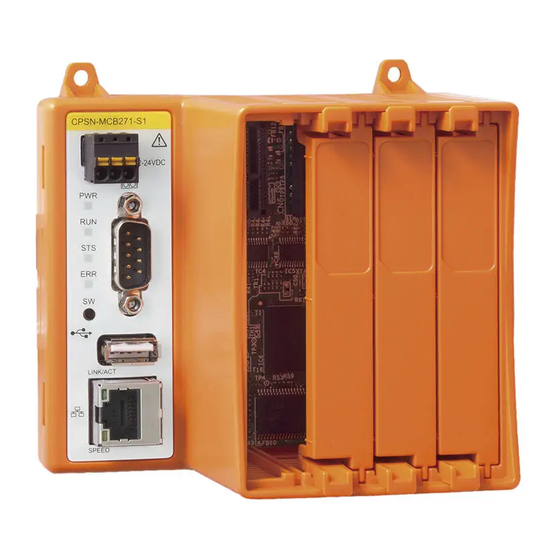
3 Nomenclature and Functions 3. Nomenclature and Functions Nomenclature of Components Component names of the products are shown in Figure 3.1 and Figure 3.2. ① ⑦ ② ③ ⑧ ⑨ ④ ⑤ LINK/AC T ⑥ SPEED Figure 3.1. CPSN-MCB271-S1 -041 Nomenclature of components (1) Power Connector : Use the power connector (3 pin connector), included in this package. -
Page 35: Component Functions
3 Nomenclature and Functions Component Functions Power Connector (12 - 24VDC) Use the 3-pin connector, included in this package. Connector type : DEGSON 15EDGKD-3.5-03P-13-00A(H) (or equivalent) Table 3.1. Power connector Pin No Signal name Meaning Frame ground Power supply (GND) Power supply (12 - 24VDC) CPSN-MCB271-S1-041 Reference Manual (Hardware) -
Page 36: Led
3 Nomenclature and Functions This product is equipped with LEDs (PWR [power], RUN, STS [status], and ERR [error]) that indicate the status. Table 3.2. LED Meaning Operation Initialization is complete. No power supplied. Flashing Initialization is in progress. Continuous PWR(Green) flashing An initialization error occurred. -
Page 37: Rs-232C Interface (Com)
3 Nomenclature and Functions RS-232C Interface (COM) This product has 1port of RS-232C compliant serial ports of a baud rate 921,600bps (Maximum). Table 3.3. Serial Ports connector No.4-40UNC Inch nut Pin No. Signal Direction Meaning name Input Carrier detection Input Received data Output Transmitted data... -
Page 38: Push Switch (Sw)
3 Nomenclature and Functions Push Switch (SW) This controls the product's power supply. Start in recovery mode: Use this procedure if you need to recover the product when the firmware is corrupted. (Procedure) (1) While holding down the push switch, turn the power ON. (2) When PWR (green LED) lights and RUN (green LED) turns off, the product starts operating in recovery mode. -
Page 39: Lan Port (Lan)
3 Nomenclature and Functions LAN Port (LAN) This product have 1 port of Ethernet. - Network type : 10BASE-T/100BASE-TX - Transmission speed : 10M/100M bps - Maximum network path length : 100m /segment Table 3.5. LAN port Link /Act Speed Pin No. -
Page 40: Expansion Slot
3 Nomenclature and Functions Expansion slot This product has four I/O slots in which you can install I/O modules. These slots are used to supply power to and communicate with the I/O modules. CAUTION Do not install or remove I/O modules while power is being supplied to this product. Be sure to check that the LEDs on the main unit are off before installing or removing modules. - Page 41 3 Nomenclature and Functions CPSN-MCB271-S1-041 Reference Manual (Hardware)
-
Page 42: System Reference
4 System Reference 4. System Reference Specifications Table 4.1. Function specifications <1/2> Item CPSN-MCB271-S1-041 ARM Cortex-M3 180MHz Memory On Board 16MB SDRAM On-Board 4MB NOR Flash for OS FeRAM On-Board 32kB Transmission standard 10BASE-T/100BASE-TX The number of channels Connector RJ-45 Connector Speed(Orange), Link / Act(Green) Transmission standard USB2.0 standard follow... -
Page 43: Power Requirements
Before you restart the power, give the product for at least one second (or more) of the power OFF time after PWR-LED is turned off. When you use with the CPS-PWD-30AW24-01 (by CONTEC), instantaneous voltage drop allowed time will be 20 millisecond or less. -
Page 44: Physical Dimensions
4 System Reference Physical Dimensions Figure 4.1. Physical dimensions CPSN-MCB271-S1-041 Reference Manual (Hardware) - Page 45 4 System Reference CPSN-MCB271-S1-041 Reference Manual (Hardware)
-
Page 46: List Of Optional Products
: with digital output (output 8 channels, No built-in power supply) - CPSN-DI-08BL : with digital output (output 8 channels, built-in power supply) - CPSN-AI-1208LI : with analog input - CPSN-COM-1PD : with RS-422A/485 (1channel) * Visit the Contec website regarding information on the optional products. CPSN-MCB271-S1-041 Reference Manual (Hardware) - Page 47 CONTEC CO., LTD. January 2018 Edition 3-9-31, Himesato, Nishiyodogawa-ku, Osaka 555-0025, Japan https://www.contec.com/ No part of this document may be copied or reproduced in any form by any means without prior written consent of CONTEC CO., LTD. [01122018] [01122018] Management No. NA05978 Parts No.