Table of Contents
Advertisement
Advertisement
Table of Contents

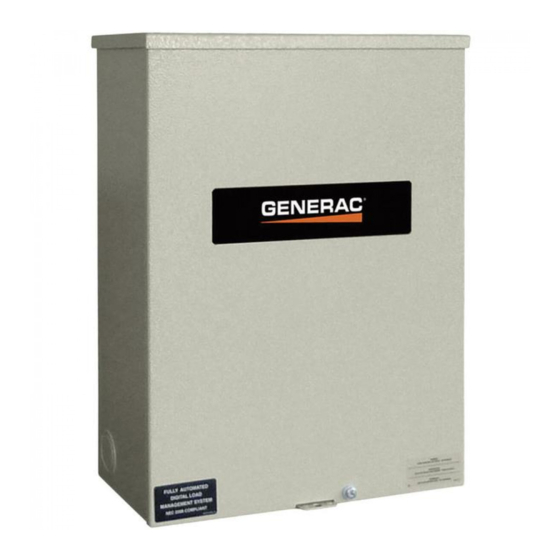
Summary of Contents for Generac Power Systems RTS Series
- Page 1 Owner's Manual 600 and 800 Amp RTS Automatic Transfer Switch...
- Page 2 Safety Rules SAVE THESE INSTRUCTIONS! Read the following information carefully before attempting to install, operate or service this equipment. Also read the instructions and information on tags, decals, and labels that may be affixed to the transfer switch. Replace any decal or label that is no longer legible. DANGER! Connection of a generator to an electrical system normally supplied by an electric util- ...
-
Page 3: Table Of Contents
Table of Contents • If work must be done on this equipment while standing on metal Safety Rules ..........Inside Front Cover or concrete, place insulative mats over a dry wood platform. General Information ..............2 Work on this equipment only while standing on such insulative mats. -
Page 4: Safety Rules
General Information INTRODUCTION TRANSFER SWITCH DATA This manual has been prepared especially for the purpose of famil- LABEL iarizing personnel with the design, application, installation, opera- A DATA LABEL is permanently affixed to the transfer switch enclo- tion and servicing of the applicable equipment. Read the manual sure. -
Page 5: Installation
Installation INTRODUCTION TO 2.4.1 3-POLE MECHANISM INSTALLATION These switches (Figure 2.1) are used with a three phase system, when the three phase NEUTRAL line is to be connected to a This equipment has been wired and tested at the factory. Installing NEUTRAL lug and is not to be switched. -
Page 6: Connecting Control Wires
Operation Proper conductor tightening torque values are on the decal inside Figure 2.2 – Auxiliary Contacts the enclosure door. Connect power source load conductors to clearly marked transfer mechanism terminal lugs as follows Connect UTILITY (NORMAL) power source cables to switch terminals N1, N2, (N3). -
Page 7: Manual Operation
Operation MANUAL OPERATION 3.2.1 TRIP TO NEUTRAL POSITION Remove handle from the square lug at the upper left corner of the switch. Insert a screwdriver into the “T” hole and push inward. The main contact should trip to the neutral position and the word OFF Do NOT manually transfer under load. -
Page 8: Close To Emergency Source Side
Operation 3.2.2 CLOSE TO EMERGENCY SOURCE SIDE With handle attached to the actuating shaft. Move manual handle upward as indicated by arrow in illustration until it stops. DO NOT Before proceeding, verify the position of the switch by observing FORCE. Confirm main contacts close to UTILITY source when window “A”... -
Page 9: 3.3.2 Generator Voltage Checks
Operation Three-phase only. Locate the 3 phase power monitor relay. With an accurate AC voltmeter and frequency meter, check the Verify the following: no-load, voltage and frequency. LED Green and ON (For an explanation of all of the LED func- Single-phase generator supply: tions, see the decal on the side of the power monitor.) Measure across ATS terminal lugs E1 to E2;... -
Page 10: Generator Tests Under Load
Operation GENERATOR TESTS UNDER LOAD Set the generator's main circuit breaker to its OFF or OPEN position. Manually actuate the transfer switch main contacts to their emergency (Standby) position. Refer to “Manual Operation”. To start the generator, set the AUTO/OFF/MANUAL switch to MANUAL. -
Page 11: Interconnection Diagram
Interconnection Diagram Drawing No. 0J0911-C A7822-S 600MCM WS16-0F... -
Page 12: Installation Diagram
Installation Diagram Drawing No. 0J0915-A... - Page 13 Installation Diagram Drawing No. 0J0915-A...
-
Page 14: Notes
Notes... - Page 15 Notes...
- Page 16 Part No. 0J0917 Revision C (08/06/13) Printed in U.S.A.
- Page 20 0J0901 E NCL NEMA 3R 36 X 60 X 20 RTS 0F6521 DECAL RTS T RANS FER S W NE MA 3R 038150 WASHER FLAT #8 ZINC 095282 DECAL LI VE CIRCUIT 022264 WASHER LOCK #8-M4 0E8594 DECAL E NCLOSURE NOTE NE MA 3R 051715 NUT HEX M4-0.


