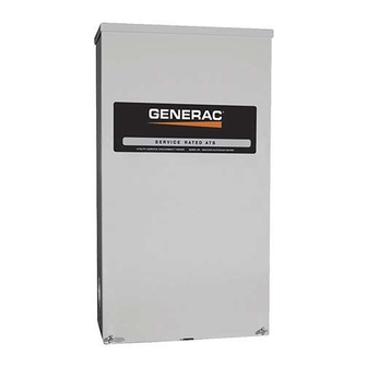
Summary of Contents for Generac Power Systems RTS
- Page 1 RTS Automatic Transfer Switch TECHNICAL MANUAL A new standard of reliability This manual should remain with the unit.
- Page 2 Generac Power Systems, Inc., hereafter referred to as the “manu- This symbol points out important safety informa- facturer”, cannot anticipate every possible circumstance that...
-
Page 3: Table Of Contents
Table of Contents Safety Rules ..........Inside Front Cover • If work must be done on this equipment while standing on metal or concrete, place insulative mats over a dry wood platform. Section 1 — General Information ..........2 Work on this equipment only while standing on such insulative 1.1 Introduction ................ -
Page 4: Safety Rules
Section 1 — General Information RTS “HS” Type Transfer Switch INTRODUCTION TRANSFER SWITCH DATA This manual has been prepared especially for the purpose of famil- DECAL iarizing personnel with the design, application, installation, opera- A DATA DECAL is permanently affixed to the transfer switch enclo- tion and servicing of the applicable equipment. -
Page 5: Section 2 - Installation
Section 2 — Installation RTS “HS” Type Transfer Switch INTRODUCTION TO 2.4.1 2-POLE MECHANISM INSTALLATION These switches (Figure 2.1) are used with a single-phase system, when the single-phase NEUTRAL line is to be connected to a This equipment has been wired and tested at the factory. Installing Neutral Lug and is not to be switched. -
Page 6: Connecting Start Circuit Wires
Section 3 — Operation RTS “HS” Type Transfer Switch MANUAL OPERATION Connect power source load conductors to clearly marked transfer mechanism terminal lugs as follows: DANGER Connect UTILITY (NORMAL) power source cables to switch terminals N1, N2. Do NOT manually transfer under load. -
Page 7: Voltage Checks
Section 3 — Operation RTS “HS” Type Transfer Switch Figure 3.1 — Actuating Transfer Switch Attach handle to actuating shaft. NOTE: Return handle to storage position in enclosure when finished with manual transfer. Move handle Move handle UP for the... -
Page 8: Generator Tests Under Load
Section 3 — Operation RTS “HS” Type Transfer Switch Set the generator’s main circuit breaker (CB1) to its OFF or When checkout under load is complete, set main circuit OPEN position. breaker of the generator to its OFF or OPEN position. -
Page 9: Section 4 - Notes
Section 4 — Notes RTS “HS” Type Transfer Switch... - Page 10 Section 4 — Notes RTS “HS” Type Transfer Switch...
- Page 11 Section 4 — Notes RTS “HS” Type Transfer Switch...
-
Page 12: Section 5 - Installation Diagram
Section 5 — Installation Diagram RTS “HS” Type Transfer Switch Drawing No. 0G6832-A... -
Page 13: Section 6 - Electrical Data
Section 6 — Electrical Data RTS “HS” Type Transfer Switch Transfer Switch Interconnections - Drawing No. 0F6941-A... - Page 14 Section 6 — Electrical Data RTS “HS” Type Transfer Switch Electrical Schematic - Drawing No. 0F6768-A...
- Page 15 Section 6 — Electrical Data RTS “HS” Type Transfer Switch Electrical Schematic - Drawing No. 0F6768-A...
-
Page 16: Section 7 - Exploded Views & Parts Lists
Section 7 — Exploded Views and Parts List RTS “HS” Type Transfer Switch 100A Transfer Switch Assembly – Drawing No. 0G6023$-D... - Page 17 Section 7 — Exploded Views and Parts List RTS “HS” Type Transfer Switch 100A Transfer Switch Assembly – Drawing No. 0G6023$-D ITEM PART NO. QTY. DESCRIPTION 0C2237 TR SW-HSB 100A 2P 250V 074908 SCREW HHTT M5-0.8 X 10 BP 0G2000...
- Page 18 Section 7 — Exploded Views and Parts List RTS “HS” Type Transfer Switch 200A Transfer Switch Assembly – Drawing No. 0G6037$-D...
- Page 19 Section 7 — Exploded Views and Parts List RTS “HS” Type Transfer Switch 200A Transfer Switch Assembly – Drawing No. 0G6037$-D ITEM PART NO. QTY. DESCRIPTION 0D9618 XFRSW HSB 200A 2P 250V 074908 SCREW HHTT M5-0.8 X 10 BP 0E3375...
-
Page 20: Section 8 - Warranty/Service
GENERAC POWER SYSTEMS, INC. WARRANTY/SERVICE Generac Power Systems, Inc. will warrant from the date of purchase that our transfer switch will be free from defects in material and workmanship for the items and periods set forth in the warranty statement found in the owners manual of the Generac Power Systems Inc.


