Table of Contents
Advertisement
Quick Links
Para español , visita:
http://www.generac.com/service‐support/product‐support‐lookup
SAVE THIS MANUAL FOR FUTURE REFERENCE
Owner's Manual
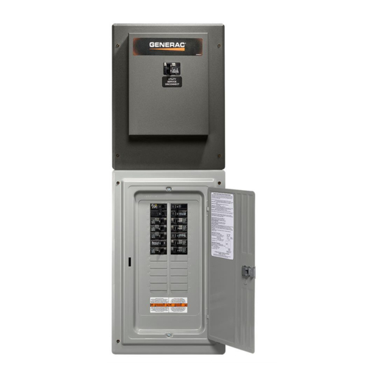
Automatic Transfer Switch
with Integrated Load Center
100–200 Amp, Service Entrance
Model Number
RTG24SHA1 (100A)
RTG42SHA1 (200A)
MODEL NUMBER: _________________________
SERIAL NUMBER: _________________________
DATE PURCHASED:________________________
Register your Generac product at:
WWW.GENERAC.COM
888-436-3722
For
Advertisement
Table of Contents

Related Manuals for Generac Power Systems RTG24SHA1


Summary of Contents for Generac Power Systems RTG24SHA1
- Page 1 Owner’s Manual Automatic Transfer Switch with Integrated Load Center 100–200 Amp, Service Entrance Model Number RTG24SHA1 (100A) RTG42SHA1 (200A) MODEL NUMBER: _________________________ SERIAL NUMBER: _________________________ DATE PURCHASED:________________________ Register your Generac product at: WWW.GENERAC.COM 888-436-3722 Para español , visita: http://www.generac.com/service‐support/product‐support‐lookup SAVE THIS MANUAL FOR FUTURE REFERENCE...
- Page 2 WARNING California Proposition 65. Engine exhaust and some of its constituents are known to the state of California to cause cancer, birth defects, and other reproductive harm. (000004) WARNING California Proposition 65. This product contains or emits chemicals known to the state of California to cause cancer, birth defects, and other reproductive harm.
-
Page 3: Table Of Contents
Table of Contents Section 1: Introduction and Safety Section 4: Operation Introduction ............1 Functional Tests and Adjustments ....13 Safety Rules ............1 Manual Operation ..........13 Close to Utility Source Side ........13 Safety Symbols and Meanings ......1 Close to Generator Source Side ........14 Electrical Hazards .......... - Page 4 Table of Contents This page intentionally left blank. Automatic Transfer Switch Owner’s Manual...
-
Page 5: Section 1: Introduction And Safety
Section 1: Introduction and Safety Introduction Safety Rules Thank you for purchasing a Generac Power Systems Inc. The manufacturer cannot anticipate every possible product. This unit has been designed to provide high circumstance that might involve a hazard. The warnings... -
Page 6: Electrical Hazards
Introduction and Safety Electrical Hazards DANGER DANGER Electrocution. High voltage is present at Equipment malfunction. Installing a dirty or damaged transfer switch and terminals. Contact with live transfer switch will cause equipment malfunction and terminals will result in death or serious injury. will result in death or serious injury. -
Page 7: General Hazards
Introduction and Safety General Hazards DANGER DANGER Electrocution. In the event of electrical accident, Electrical backfeed. Use only approved switchgear to immediately shut power OFF. Use non-conductive isolate generator from the normal power source. implements to free victim from live conductor. Apply Failure to do so will result in death, serious injury, first aid and get medical help. - Page 8 Introduction and Safety This page intentionally left blank. Automatic Transfer Switch Owner’s Manual...
-
Page 9: Section 2: General Information
General Information Section 2: General Information Introduction This UL listed transfer switch is for use in optional standby systems only (NEC article 702). Thank you for purchasing a Generac transfer switch. This A 100A rated switch is suitable for use on utilty services manual has been prepared especially for the purpose of capable of delivering not more than 10,000 RMS familiarizing personnel with the design, application,... -
Page 10: Load Center Circuit Breakers
General Information Transfer Switch Data Decal Load Center Circuit Breakers This switch is listed for use with the following one inch A data decal is permanently affixed to the transfer switch breakers: enclosure. Use this transfer switch only with the specific limits shown on the data decal and on other decals and Manufacturer SCCR Amperage Rating... -
Page 11: Smart A/C Module (Sacm)
General Information Smart A/C Module (SACM) Figure 2-2. Up to four air conditioner loads can be managed by the SACM. The SACM manages, or temporarily disconnects, the connected loads in the event of a drop in generator frequency (overload). Loads to be managed are in 4 priority levels on the module. - Page 12 General Information This page intentionally left blank. Automatic Transfer Switch Owner’s Manual...
-
Page 13: Section 3: Installation
Installation Section 3: Installation Introduction to Installation This transfer switch is mounted in a NEMA 1 type enclosure. It can only be mounted indoors and should be This equipment has been wired and tested at the factory. based on the layout of installation, convenience and Installing the switch includes the following procedures: proximity to the utility supply and load center. -
Page 14: Installing Branch Circuit Conductors
Installation Connecting Power Source and 4. See Figure 3-2. Insert tab on each breaker (A) into the hook on the bus (B). Push the breaker into the Generator Power Supply bus until it snaps into place. DANGER Electrocution. Turn utility and emergency power supplies to OFF before connecting power source and load lines. -
Page 15: Connecting Start Circuit Wires
Installation Connecting Smart A/C Module Conductor sizes must be adequate to handle the maximum current to which they will be subjected, based (SACM) on the 75°C column of tables, charts, etc. used to size Figure 3-4. The Smart A/C Module (SACM) can conductors. -
Page 16: Auxiliary Contact
Installation Thermostat 1 0 GROUND 194 +12V Air Conditioner 1 23 TRANSFER 00 NEUTRAL Thermostat 4 A/C 1 Air Conditioner 4 A/C 2 A/C 1 Thermostat 2 A/C 3 A/C 2 A/C 3 Air Conditioner 2 A/C 4 A/C 4 Thermostat 3 Air Conditioner 3 003693... -
Page 17: Section 4: Operation
Operation Section 4: Operation Functional Tests and Adjustments • Manual operation handle in the DOWN position— LOAD terminals (T1, T2) connected Following transfer switch installation and interconnection, EMERGENCY terminals (E1, E2). inspect the entire installation carefully. A competent, qualified electrician should inspect it. The installation CAUTION should comply strictly with all applicable codes, standards, and regulations. -
Page 18: Close To Generator Source Side
Operation Close to Generator Source Side DANGER Figure 4-1. Before proceeding, verify the position of the switch by observing the position of the manual Electrocution. High voltage is present at operation handle. If the handle is DOWN, the contacts transfer switch and terminals. Contact with live terminals will result in death or serious injury. -
Page 19: Checking Automatic Operation
Operation Installation Summary • Verify that the gas pressure remains within acceptable parameters (see the generator 1. Verify the installation has been properly performed Installation Guidelines manual). as outlined by the manufacturer and that it meets • Let the generator run under rated load for at all applicable laws and codes. -
Page 20: Testing The Smart Management Module
Operation Testing The Smart Management Module Refer to the SMM Owner’s/Installation Manual for testing that product. Automatic Transfer Switch Owner’s Manual... -
Page 21: Section 5: Drawings And Diagrams
Drawings and Diagrams Section 5: Drawings and Diagrams Installation Drawings Installation Drawing No. 10000005900 (100A) Automatic Transfer Switch Owner’s Manual... -
Page 22: Installation Drawing No. 10000005900 (200A)
Drawings and Diagrams Installation Drawing No. 10000005900 (200A) Automatic Transfer Switch Owner’s Manual... -
Page 23: Interconnection Drawings
Drawings and Diagrams Interconnection Drawings Interconnection Drawing 10000005901—Air-Cooled 100A Generator (page 1 of 2) INTERCONNECTION DRAWING REVISION: "A" AIR COOLED GENERATOR - RTG24SHA1 DRAWING #: 10000005901 DATE: 08/31/16 Automatic Transfer Switch Owner’s Manual... -
Page 24: Interconnection Drawing 10000005901-Air-Cooled 100A Generator
Drawings and Diagrams Interconnection Drawing 10000005901—Air-Cooled 100A Generator (page 2 of 2) INTERCONNECTION DRAWING REVISION: "A" AIR COOLED GENERATOR - RTG24SHA1 DRAWING #: 10000005901 DATE: 08/31/16 Automatic Transfer Switch Owner’s Manual... -
Page 25: Interconnection Drawing 10000005901-Air-Cooled 200A Generator
Drawings and Diagrams Interconnection Drawing 10000005901—Air-Cooled 200A Generator (page 1 of 2) INTERCONNECTION DRAWING REVISION: "A" AIR COOLED GENERATOR - RTG42SHA1 DRAWING #: 10000005901 DATE: 08/31/16 Automatic Transfer Switch Owner’s Manual... -
Page 26: Interconnection Drawing 10000005901-Air-Cooled 200A Generator
Drawings and Diagrams Interconnection Drawing 10000005901—Air-Cooled 200A Generator (page 2 of 2) INTERCONNECTION DRAWING REVISION: "A" AIR COOLED GENERATOR - RTG42SHA1 DRAWING #: 10000005901 DATE: 8/31/16 Automatic Transfer Switch Owner’s Manual... -
Page 27: Interconnection Drawing 10000005855-Liquid-Cooled 100A Generator
Drawings and Diagrams Interconnection Drawing 10000005855—Liquid-Cooled 100A Generator (page 1 of 2) INTERCONNECTION DRAWING REVISION: "A" LIQUID COOLED GENERATOR - RTG24SHA1 DRAWING #: 10000005855 DATE:08/31/16 Automatic Transfer Switch Owner’s Manual... -
Page 28: Interconnection Drawing 10000005855-Liquid-Cooled 100A Generator
Drawings and Diagrams Interconnection Drawing 10000005855—Liquid-Cooled 100A Generator (page 2 of 2) INTERCONNECTION DRAWING REVISION: "A" LIQUID COOLED GENERATOR - RTG24SHA1 DRAWING #: 10000005855 DATE: 08/31/16 Automatic Transfer Switch Owner’s Manual... -
Page 29: Interconnection Drawing 10000005855-Liquid-Cooled 200A Generator
Drawings and Diagrams Interconnection Drawing 10000005855—Liquid-Cooled 200A Generator (page 1 of 2) INTERCONNECTION DRAWING REVISION: "A" LIQUID COOLED GENERATOR - RTG42SHA1 DRAWING #: 10000005855 DATE:08/31/16 Automatic Transfer Switch Owner’s Manual... -
Page 30: Interconnection Drawing 10000005855-Liquid-Cooled 200A Generator
Drawings and Diagrams Interconnection Drawing 10000005855—Liquid-Cooled 200A Generator (page 2 of 2) INTERCONNECTION DRAWING REVISION: "A" LIQUID COOLED GENERATOR - RTG42SHA1 DRAWING #: 10000005855 DATE: 08/31/16 Automatic Transfer Switch Owner’s Manual... - Page 32 ©2016 Generac Power Systems, Inc. Generac Power Systems, Inc. All rights reserved S45 W29290 Hwy. 59 Specifications are subject to change without notice. Waukesha, WI 53189 No reproduction allowed in any form without prior written 1-888-GENERAC (1-888-436-3722) consent from Generac Power Systems, Inc. www.generac.com...