Advertisement
Table of Contents
- 1 Table of Contents
- 2 Warning Decal Placement
- 3 Important Precautions
- 4 Before You Begin
- 5 Part Identification Chart
- 6 Assembly
- 7 The Chest Heart Rate Monitor
- 8 How to Use the Trainer
- 9 Fcc Information
- 10 Maintenance and Troubleshooting
- 11 Exercise Guidelines
- 12 Part List
- 13 Exploded Drawing
- 14 Ordering Replacement Parts
- 15 Limited Warranty
- Download this manual
proform.com
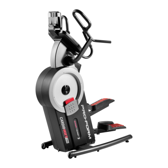
Model No. PFEL01415.5
Serial No.
Write the serial number in the space
above for reference.
ACTIVATE YOUR
WARRANTY
To register your product and
activate your warranty today,
go to my.proform.com.
CUSTOMER CARE
For service at any time, go to
proformservice.com.
Or call 1-888-533-1333
Mon.–Fri. 6 a.m.–6 p.m. MT
Sat. 8 a.m.–12 p.m. MT
Please do not contact the store.
CAUTION
Read all precautions and
instructions in this manual before
using this equipment. Keep this
manual for future reference.
Serial
Number
Decal
USER'S MANUAL
Advertisement
Table of Contents

Related Manuals for Pro-Form Cardio Hit Pro


Summary of Contents for Pro-Form Cardio Hit Pro
- Page 1 proform.com USER’S MANUAL Model No. PFEL01415.5 Serial No. Write the serial number in the space above for reference. Serial Number Decal ACTIVATE YOUR WARRANTY To register your product and activate your warranty today, go to my.proform.com. CUSTOMER CARE For service at any time, go to proformservice.com.
-
Page 2: Table Of Contents
TABLE OF CONTENTS WARNING DECAL PLACEMENT ............. . .2 IMPORTANT PRECAUTIONS . -
Page 3: Important Precautions
IMPORTANT PRECAUTIONS WARNING: To reduce the risk of burns, fire, electric shock, or injury to persons, read all important precautions and instructions in this manual and all warnings on your trainer before using your trainer. ICON assumes no responsibility for personal injury or property damage sustained by or through the use of this product. - Page 4 18. The trainer does not have a freewheel; the 20. Over exercising may result in serious injury pedals will continue to move until the fly- or death. If you feel faint, if you become short wheel stops. Reduce your pedaling speed in of breath, or if you experience pain while a controlled way.
- Page 5 STANDARD SERVICE PLANS...
-
Page 6: Before You Begin
BEFORE YOU BEGIN Thank you for selecting the revolutionary PROFORM reading this manual, please see the front cover of this ® CARDIO HIIT PRO TRAINER. The CARDIO HIIT PRO manual. To help us assist you, note the product model TRAINER trainer provides an impressive selection number and serial number before contacting us. -
Page 7: Part Identification Chart
PART IDENTIFICATION CHART Use the drawings below to identify the small parts needed for assembly. The number in parentheses below each drawing is the key number of the part, from the PART LIST near the end of this manual. The number following the key number is the quantity needed for assembly. -
Page 8: Assembly
ASSEMBLY • To hire an authorized service technician to • To identify small parts, see page 7. assemble this product, call 1-800-445-2480. • In addition to the included tool(s), assembly • Assembly requires two persons. requires the following tools: one Phillips screwdriver •... - Page 9 2. Identify the Right and Left Stabilizers (8, 9), and orient them as shown. Have a second person hold the Frame (1) and tip it to the left. IMPORTANT: Be careful not to damage the Shields (50, 51). Attach the Right Stabilizer (8) to the Frame (1) with four M10 x 20mm Screws (110);...
- Page 10 4. Attach the Right Pedal Base (2) to the Right Pedal Leg (24) with four M8 x 20mm Screws (102); start all the Screws, and then tighten them. Attach the Left Pedal Base (not shown) to the Left Pedal Leg (not shown) in the same way. 5.
- Page 11 6. See the upper drawing. With the help of a second person, orient the Console (5), the Console Cover (7), and the Console Bracket (4) as shown. Then, route the wires (A) on the Console through the Console Cover and the Console Bracket;...
- Page 12 8. While a second person holds the Console Bracket (4) near the Frame (1), connect the wires on the Console to the Main Wire (115) and to the Left and Right Pulse Wires (117, 125). Avoid pinching Tip: Avoid pinching the wires. Attach the the wires Console Bracket (4) to the Frame (1) with two M8 x 86mm Screws (109) and two M8 x 15mm...
- Page 13 10. Identify the Rear and Front Pivot Covers (65, 66). Press a set of Rear and Front Pivot Covers (65, 66) together around the Right Handlebar (10) near the bend (A). Then, attach them to each other with two M4 x 22mm Screws (107). See the inset drawing.
-
Page 14: The Chest Heart Rate Monitor
THE CHEST HEART RATE MONITOR HOW TO PUT ON THE HEART RATE MONITOR • Store the heart rate monitor in a warm, dry place. Do not store the heart rate monitor in a plastic bag or If the heart rate monitor looks like the one shown in other container that may trap moisture. -
Page 15: How To Use The Trainer
HOW TO USE THE TRAINER HOW TO PLUG IN THE POWER CORD A temporary adapter may 2-pole Receptacle This product must be grounded. If it should mal- be used to function or break down, grounding provides a path of connect the least resistance for electric current to reduce the risk power cord Adapter... - Page 16 HOW TO MOVE THE TRAINER HOW TO EXERCISE ON THE TRAINER Due to the size and weight of the trainer, moving To mount the trainer, hold the handlebars (C) or the it requires two persons. Stand in front of the trainer, pulse grips (D) and step onto the pedal (E) that is in hold the console bracket (A), and place one foot the lower position.
- Page 17 HOW TO LEVEL THE TRAINER HOW TO USE THE TABLET HOLDER If the trainer IMPORTANT: The tablet holder (G) is designed for use with most full-size tablets. Do not place rocks slightly on any other electronic device or object in the tablet your floor during use, turn one holder.
- Page 18 CONSOLE DIAGRAM FEATURES OF THE CONSOLE When you use the manual mode of the console, you can change the resistance of the pedals with the touch The advanced console offers an array of features of a button. designed to make your workouts more effective and enjoyable.
- Page 19 HOW TO TURN ON THE POWER HOW TO USE THE TOUCH SCREEN IMPORTANT: If the trainer has been exposed to The console features a tablet with a full-color touch cold temperatures, allow it to warm to room tem- screen. The following information will help you use the perature before you turn on the power.
- Page 20 HOW TO SET UP THE CONSOLE To use the manual mode, see this page. To use a map workout or an onboard workout, see page Before you use the trainer for the first time, set up the 22. To create a draw-your-own-map workout, see page 24.
- Page 21 4. Follow your progress. with your palms resting against the contacts. Avoid moving your hands or gripping the contacts The console offers several display modes. The tightly. display mode that you select will determine which When your pulse is detected, your heart rate workout information is shown.
- Page 22 HOW TO USE A MAP WORKOUT OR AN ONBOARD To draw your own map for a workout, see HOW TO WORKOUT CREATE A DRAW-YOUR-OWN-MAP WORKOUT on page 24. 1. Touch the screen or press any button on the console to turn on the console. When you select a workout, the screen will show an overview of the workout that includes details See HOW TO TURN ON THE POWER on...
- Page 23 5. Follow your progress. If the resistance level is too high or too low, you can manually override the setting by pressing the Resistance buttons. If you press a Resistance See step 4 on page 21. button, you can then manually control the resis- tance level (see step 3 on page 20).
- Page 24 HOW TO CREATE A DRAW-YOUR-OWN-MAP If you make a mistake, touch Undo on the left side WORKOUT of the screen. 1. Touch the screen or press any button on the The screen will display the elevation and distance console to turn on the console. statistics for your workout.
- Page 25 HOW TO USE AN IFIT WORKOUT 4. Select an iFit workout that you have previously added to your schedule on iFit.com. To use an iFit workout, the console must be connected IMPORTANT: Before iFit workouts will load, you to a wireless network (see HOW TO CONNECT TO A must add them to your schedule on iFit.com WIRELESS NETWORK on page 27).
- Page 26 HOW TO CHANGE CONSOLE SETTINGS 3. View the console tour presentation. IMPORTANT: Some of the settings and features To view a tour presentation that will guide you described may not be enabled. Occasionally, a through the features of the console, touch How It firmware update may cause your console to function Works.
- Page 27 HOW TO CONNECT TO A WIRELESS NETWORK Note: You must have your own wireless network and an 802.11b/g/n router with SSID broadcast To use iFit workouts and to use several other features enabled (hidden networks are not supported). of the console, the console must be connected to a wireless network.
-
Page 28: Fcc Information
HOW TO USE THE SOUND SYSTEM HOW TO CONNECT AN HDMI CABLE To play music or audio books through the console To show your console screen on a TV or monitor, plug sound system while you exercise, plug a 3.5 mm male an HDMI cable (not included) into the port on the con- sole and into a port on your TV or monitor;... -
Page 29: Maintenance And Troubleshooting
MAINTENANCE AND TROUBLESHOOTING MAINTENANCE If the console does not boot up properly, or if the con- Regular maintenance is important for optimal sole freezes and does not performance and to reduce wear. Inspect and properly respond, reset the console tighten all parts each time the trainer is used. Replace to the factory default set- any worn parts immediately. - Page 30 HOW TO ADJUST THE REED SWITCH HOW TO ADJUST THE DRIVE BELT If the console does not display correct feedback, the If the pedals slip while you are pedaling, even while reed switch should be adjusted. To adjust the reed the resistance is adjusted to the highest level, the drive switch, first unplug the power adapter.
-
Page 31: Exercise Guidelines
EXERCISE GUIDELINES Burning Fat—To burn fat effectively, you must exer- WARNING: cise at a low intensity level for a sustained period of Before beginning this time. During the first few minutes of exercise, your or any exercise program, consult your physi- body uses carbohydrate calories for energy. -
Page 32: Part List
PART LIST Model No. PFEL01415.5 R0718A Key No. Qty. Description Key No. Qty. Description Frame Right Shield Right Pedal Base Front Cover Left Pedal Base Rear Cover Console Bracket Accessory Tray Base Console Stabilizer Cap Tablet Holder Foot Console Cover Wheel Right Stabilizer Right Wheel Cover... - Page 33 Key No. Qty. Description Key No. Qty. Description M4 x 16mm Flat Head Screw Power Cord M8 x 20mm Screw Crank Cover Disc Cap Screw Slant Cap M6 x 110mm Screw Pulley Magnet M8 x 25mm Screw Power Board M4 x 16mm Screw Chest Heart Rate Monitor M4 x 22mm Screw Grommet...
-
Page 34: Exploded Drawing
EXPLODED DRAWING A Model No. PFEL01415.5 R0718A... - Page 35 EXPLODED DRAWING B Model No. PFEL01415.5 R0718A...
-
Page 36: Ordering Replacement Parts
ORDERING REPLACEMENT PARTS To order replacement parts, please see the front cover of this manual. To help us assist you, be prepared to provide the following information when contacting us: • the model number and serial number of the product (see the front cover of this manual) •...