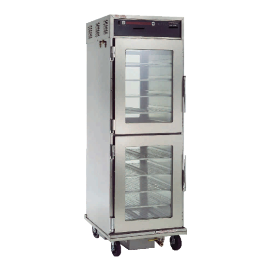
Henny Penny HHC-980 Technical Manual
Humidified holding cabinets
Hide thumbs
Also See for HHC-980:
- User manual (1 page) ,
- Operator's manual (38 pages) ,
- Operator's manual (28 pages)

Related Manuals for Henny Penny HHC-980


Summary of Contents for Henny Penny HHC-980
- Page 1 Henny Penny Humidified Holding Cabinets Model HHC-980 Model HHC-983 TECHNICAL MANUAL...
- Page 3 During this time, any frypot that fails due to manufacturing or workmanship issues will be replaced at no char g e for parts, labor , or freight. Henny Penny will either install a new frypot at no cost or provide a new or reconditioned replacement fryer at no cost.
-
Page 4: Table Of Contents
Model HHC-980/983 TABLE OF CONTENTS Section Page Section 1. TROUBLESHOOTING 1-1. Introduction ......................... 1-1. Safety .......................... 1-3. Troubleshooting ......................1-4. Error Codes and Warnings ..................1-5. Info Mode ........................Section 2. LEVEL 2 PROGRAMMING 2-1. Introduction ......................... 2-2. Tech Mode ........................ -
Page 5: Section 1. Troubleshooting
Model HHC-980/983 SECTION 1. TROUBLESHOOTING This section provides troubleshooting information in the form 1-1. INTRODUCTION of an easy to read table. If a problem occurs during the first operation of a cabinet, recheck the installation per the Installation Section of the Operator’s Manual... - Page 6 Model HHC-980/983 1-3. TROUBLESHOOTING (continued) Problem Cause Correction OPERATION A. Product not • Doors left open • Keep doors closed except holding temperature to load and serve product • Product held too long • Hold product only for recom- mended times •...
- Page 7 Model HHC-980/983 1-3. TROUBLESHOOTING (continued) Problem Cause Correction OPERATION (Continued) C. Product dry • Bad float switch (E-18) • Replace float switch • Bad water heater high limit • Replace high limit • Bad water heater • Check heater and replace if bad;...
- Page 8 Model HHC-980/983 1-3. TROUBLESHOOTING (continued) Problem Cause Correction HEATING SYSTEM (Continued) C. Unit Overheating • Blower not working • Check blower and replace if bad; (“E-5”) see Tech Mode item 18. • Bad control board • Replace control board • Relay stuck closed...
-
Page 9: Error Codes And Warnings
Model HHC-980/983 The display shows the following error codes and warnings 1-4. ERROR CODES AND when a fault is detected, along with an alarm sound. Both the WARNINGS heat and humidity systems shut down, except when specified otherwise. Display Cause Panel Board Correction “E-4... - Page 10 Model HHC-980/983 1-4. ERROR CODES AND WARNINGS (Continued) Display Cause Panel Board Correction • Turn switch to OFF position, then back to “ E-6B AIR TEMP SENSOR • Faulty air temperature ON; if the display shows “E-6”, the FAILED SHORTED”...
- Page 11 Model HHC-980/983 1-3. ERROR CODES AND WARNINGS (Continued) Display Cause Panel Board Correction “E-41 SYSTEM DA TA LOST” • Memory Scrambled • Turn switch to OFF position, then back to ON; if the display shows “E-41”, the control should be re-initialized (see Pro- gramming Section);...
-
Page 12: Info Mode
Model HHC-980/983 This mode records historic information on the holding cabinet 1-4. INFO MODE and operator performance, which could help in troubleshooting a problem. Press at the same time and “*INFO MODE*” shows on display. Press to access the steps and press to view the statistics within each step. - Page 13 Model HHC-980/983 1. E-LOG (error code log) 1-4. INFO MODE (Continued) Press and “1A. (date & time) *NOW* shows in display. This is the present date and time. Press and if a error was recorded, “1B. (date, time, and error code information)” shows in display. This is the latest error code that the controls recorded.
- Page 14 Model HHC-980/983 1-4. INFO MODE (Continued) 3. OUTPUTS/INPUTS (Continued) d. “S_F_W_A_ P_ F_” shows in the display. If the output or input signal is detected, “*” shows beside the letter. Ex: “S*”. If the control senses a problem with the output, “*”...
-
Page 15: Section 2. Level 2 Programming
Model HHC-980/983 SECTION 2. LEVEL 2 PROGRAMMING The Tech Mode and Stats Mode in the Level 2 Programming 2-1. INTRODUCTION Section, have information that could help in troubleshooting a problem with the unit. 2-2. TECH MODE Press and hold until “L-2 LEVEL 2”, followed by, “SP PROG”, shows in display. - Page 16 Model HHC-980/983 2-2. TECH MODE (Continued) T-1: Software This section shows “PN/ID/SRL” Press . Henny Penny eprom part number is displayed. Press . Customer ID (i.e. Pizza Hut) is displayed Press . Software revision is displayed. T-2: Cabinet Version Shows the model number, e.i. HHC-983...
- Page 17 Model HHC-980/983 2-2. TECH MODE (Continued) T10: Air Temperature - Calibration/Offset/Highest A user calibration to make sure the display shows the actual air temperature Press and hold and use to set the display to match the actual temperature. (+/-15 Press and hold to change the amount of the offset.
- Page 18 T19: Total Initialization Completely resets any accumulated information and changed settings in the controls; contact Henny Penny Corp. before completing this step!
-
Page 19: Stats Mode
Model HHC-980/983 Press and hold until “L-2 LEVEL 2”, followed by, 2-3. STATS MODE “SP PROG”, shows in display. Press 4 times and “STATS”, followed by, “ENTER CODE” shows in display. Enter code, to access the following items: ST-1 Power live hours... - Page 20 Model HHC-980/983 2-3. STATS MODE (Continued) ST-1: Power Live Hours Shows the number of hours the unit has been plugged in ST-2: Power On Hours Shows the number of hours the control has been on ST-3: Power Ups Count Shows the number of times the control has been turned on...
- Page 21 Model HHC-980/983 2-3. STATS MODE (Continued) ST-13: Highest Humidity Value Shows the highest humidity value sensed by the humidity sensor ST-14: Highest CPU Temperature Shows the highest control board temperature sensed by the control ST-15: Water heater (too hot) cycle count...
-
Page 22: Data Logging And Manufacturing Mode
Allows the user to reset all data stored in the Stats Mode; press and hold for 3 seconds The Data Logging and Manufacturing Modes are mainly for 2-4. DATA LOGGING AND Henny Penny use only. For more information on these modes, MANUFACTURING contact the Service Department at 1-800-417- 8405, or MODE 1-937-456-8405. -
Page 23: Section 3. Maintenance
Model HHC-980/983 SECTION 3. MAINTENANCE This section provides procedures for the checkout and re- 3-1. INTRODUCTION placement of the various parts used within the merchandiser. Before replacing any parts, refer to the Troubleshooting sec- tion. It will aid you in determining the cause of the malfunc- tion. - Page 24 Model HHC-980/983 3-3. HUMIDITY SENSOR CALIBRATION AND REPLACEMENT (Continued) 4. Pull the sensor assembly from the box and disconnect the wires. Figure 3-3. 5. Connect wires of new sensor and attach the sensor to the box. Follow the calibration instructions below before re- attaching the sensor cover.
- Page 25 Model HHC-980/983 6. Using the hidden buttons, (Figure 3-5), enter code of 3-3. HUMIDITY SENSOR 11221122. (Hidden buttons 1 through 5 left to right) CALIBRATION AND REPLACEMENT (Continued) Figure 3-5 7. Press to step through menu to step 13. 8. Insert the two prongs of the calibration board marked 20% into the humidity sensor.
-
Page 26: Fuse And Fuse Holder Assembly
Model HHC-980/983 If the unit (non-CE) is completely inoperative, but power exists 3-4. FUSE AND FUSE at the wall receptacle, check the 15 amp fuse(s) and fuse HOLDER ASSEMBLY holder(s) as follows: To avoid electrical shock or property damage, move the power switch to OFF and disconnect main circuit breaker, or unplug cord at wall receptacle. -
Page 27: Power Switch Replacement
Model HHC-980/983 3-5. POWER SWITCH REPLACEMENT To avoid electrical shock or property damage, move the power switch to OFF and disconnect main circuit breaker, or unplug cord at wall receptacle. 1. Using a Phillip’s head screwdriver, remove the four screws securing the front panel. -
Page 28: Air Temperature Probe Replacement
Model HHC-980/983 3-6. AIR TEMPERATURE PROBE REPLACEMENT To avoid electrical shock or property damage, move the power switch to OFF and disconnect main circuit breaker, or unplug cord at wall receptacle. 1. Using a Phillip’s head screwdriver, remove the four screws securing the front panel. - Page 29 Model HHC-980/983 RTD Resistance Chart...
-
Page 30: Transformer Replacement
Model HHC-980/983 3-7. TRANSFORMER REPLACEMENT To avoid electrical shock or property damage, move the power switch to OFF and disconnect main circuit breaker, or unplug cord at wall receptacle. 1. Using a Phillip’s head screwdriver, remove the four screws securing the front panel. -
Page 31: Relay Replacement
Model HHC-980/983 3-8. RELAY REPLACEMENT To avoid electrical shock or property damage, move the power switch to OFF and disconnect main circuit breaker, or unplug cord at wall receptacle. Checkout: 1. Using a Phillip’s head screwdriver, remove the four screws securing the front panel. -
Page 32: Module Top Removal
Model HHC-980/983 3-8. RELAY REPLACEMENT (Continued) 7. Label wires and then remove wires from relay using a Phillip’s head screwdriver. Figure 3-18. 8. Using a Phillip’s head screwdriver, remove the 2 screws securing the relay and remove relay from unit. Figure 3-19. -
Page 33: Cooling Fan Replacement
Model HHC-980/983 3-10. COOLING FAN REPLACEMENT To avoid electrical shock or property damage, move the power switch to OFF and disconnect main circuit breaker, or unplug cord at wall receptacle. 1. Refer to section 3-10 for module top removal. Figure 3-22 2. -
Page 34: Blower Motor Replacement
Model HHC-980/983 3-12. BLOWER MOTOR REPLACEMENT To avoid electrical shock or property damage, move the power switch to OFF and disconnect main circuit breaker, or unplug cord at wall receptacle. 1. Follow the instructions in section 3-10 on removing the module top. -
Page 35: Air Heater Replacement
Model HHC-980/983 3-13. AIR HEATER REPLACEMENT To avoid electrical shock or property damage, move the power switch to OFF and disconnect main circuit breaker, or unplug cord at wall receptacle. 1. Follow the instructions in section 3-10 on removing the module top. -
Page 36: Complete Panel Or Pc Board Replacement
Model HHC-980/983 3-15. COMPLETE PANEL OR PC BOARD REPLACEMENT To avoid electrical shock or property damage, move the power switch to OFF and disconnect main circuit breaker, or unplug cord at wall receptacle. The complete control panel assembly can be replaced, or just the PC board. -
Page 37: Float Switch Replacement
Model HHC-980/983 3-16. FLOAT SWITCH REPLACEMENT To avoid electrical shock or property damage, move the power switch to OFF and disconnect main circuit breaker, or unplug cord at wall receptacle. 1. Disconnect water supply at side of cabinet. Open drain valve and empty water pan into a shallow pan or floor drain. -
Page 38: High Limit - Water Heater Replacement
Model HHC-980/983 3-17. HIGH LIMIT - WATER HEATER REPLACEMENT To avoid electrical shock or property damage, move the power switch to OFF and disconnect main circuit breaker, or unplug cord at wall receptacle. 1. Disconnect water supply at side of cabinet. Open drain valve and empty water pan into a shallow pan or floor drain. -
Page 39: Water Heater Replacement
Model HHC-980/983 3-18. WATER HEATER REPLACEMENT To avoid electrical shock or property damage, move the POWER switch to OFF and disconnect main circuit breaker, or unplug cord at wall receptacle. 1. Open drain valve and empty water pan into a shallow pan or floor drain. - Page 40 Model HHC-980/983 3-18. WATER HEATER REPLACEMENT 8. Locate the aluminum, octagon plate in the kit. Make sure the (Continued) surface is free of debris and place the plate over the 4 long studs. Figure 3-49. 9. Install new heater, making sure the flat side is towards the plate and the soldered wires are exposed, as shown in Figure 3-50.
-
Page 41: Drain Valve Replacement
Model HHC-980/983 3-19. DRAIN VALVE REPLACEMENT To avoid electrical shock or property damage, move the power switch to OFF and disconnect main circuit breaker, or unplug cord at wall receptacle. 1. Disconnect water supply at side of cabinet. Open drain valve and empty water pan into a shallow pan or floor drain. -
Page 42: Cleaning Water Strainer
Model HHC-980/983 3-20. CLEANING WATER STRAINER (Auto-fill units) 1. Disconnect water supply at side of cabinet. 2. Remove the hex cap at the bottom of the water strainer. Figure 3-50. 3. Remove the screen from inside the strainer and clean. -
Page 43: Water Valve (Solenoid) Replacement
Model HHC-980/983 3-21. WATER VALVE (SOLENOID) REPLACEMENT (Auto-fill units) (Continued) Hot water! Do not place your hand under the drain while draining the unit. Failure to follow this warning could result in severe burns and injury. 2. Remove all doors and racks from unit and carefully lay the unit on its back. -
Page 44: Door Gasket Replacement
Model HHC-980/983 3-21. WATER VALVE (SOLENOID) REPLACEMENT (Auto-fill units) (Continued) 7. Remove the fittings from both ends of the solenoid. Figure 3-56. 8. Put pipe sealant on threads and place fittings in new solenoid, making sure the strainer goes to the IN side of the solenoid. - Page 45 Model HHC-980/983 3-23...
- Page 46 Model HHC-980/983 3-24...
- Page 47 Model HHC-980/983 27485 - 120/60/1 3-25...
- Page 48 Model HHC-980/983 27486 - 208/240/60/1 3-26...
- Page 49 Model HHC-980/983 27487 - 230/50/1 3-27...
- Page 50 Model HHC-980/983 68491 3-28...
- Page 51 Model HHC-980/983 67702 ( SPO-has vent position switch) 3-29...
-
Page 52: Section 4. Parts Information
This section lists the replaceable parts of the Henny Penny 4-1. INTRODUCTION HHC-980/983 units. Use only genuine Henny Penny parts in your cabinet. Using a 4-2. GENUINE PARTS part of lesser quality or substitute design may result in damage to the unit, or personal injury . - Page 53 Model HHC-980/983 Quantity Item No. Part No. Description √ √ √ √ √ 1 63419 Speaker Assembly √ √ √ √ √ 2 63460 Transformer Assembly - 120V Pri. √ √ √ √ √ 2 63459 Transformer Assembly - 208/240V Pri.-24V Sec.
- Page 54 √ √ √ √ √ 1 14864 Kit - Control Board - 983 √ √ √ √ √ 2 63464 Power Switch 65113 Decal - HHC-980 65114 Decal - HHC-983 32768 Assy - 980 Glass Door - RH Top 1 or 2 32769...
- Page 55 Model HHC-980/983 Quantity Item No. Part No. Description √ √ √ √ √ 1 18364 Fuse Holder Assembly √ √ √ √ √ 1 EF02-007 Fuse - 15 Amp √ √ √ √ √ 1 EF02-006 Fuse Holder 26906 Power Cord Assembly - 120V -20A...
- Page 56 Model HHC-980/983 Quantity Item No. Part No. Description √ √ √ √ √ 1 14390 Kit - Humidity Sensor √ √ √ √ √ 2 64283 Probe-Air Temp √ √ √ √ √ 3* 14391 Kit - Calibration Board √ √ √ √ √ recommended parts...
- Page 57 Model HHC-980/983 Quantity Item No. Part No. Description 27155 Caster 27321 Caster - Dual 2 in. - Swivel (under counter models) FP01-127 1/2 x 1/2 90 Degree Street FP01-167 Elbow - 90 Deg. 1/2 x 3/3 BR Street (countertop models)
- Page 58 Model HHC-980/983 AUTO-WATER FILL UNITS Quantity Item No. Part No. Description FP01-152 Fitting -3/8 Hose Barb -1/8 NPT √ √ √ √ √ 2 14965 Solenoid - 120V √ √ √ √ √ 2 14967 Solenoid - 208V √ √ √ √ √ 2...
- Page 59 Model HHC-980/983 Quantity Item No. Part No. Description √ √ √ √ √ 1 25643 Gasket - Door - 980 2 or 4 √ √ √ √ √ 1 25793 Gasket - Door - 983 24909 Assy. - 983 Air Duct (use w/pizza trays) 68012 Assy.
- Page 60 Model HHC-980/983 Under Counter 983 Quantity Item No. Part No. Description 27357 Hanger - Drain Valve 26968-004 16 in. Hose - HHC-983 - 27359 under counter models) Valve - Drain (countertop & 26968-001 Hose - Water - 980/983 - 13 in.