Table of Contents
Advertisement
Quick Links
Advertisement
Table of Contents

Related Manuals for Toro TS170


Summary of Contents for Toro TS170
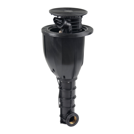
- Page 1 TS170 Large Area Sprinkler Operating Manual...
-
Page 2: Table Of Contents
5. Assembly, set-up and installation 5.1 Hazard warnings 5.2 Installation instructions 5.3 TS170 pop-up sprinkler installation diagram 5.4 Installation scheme for TS170 with rubber infill lawn 5.5 External start using key switch 5.6 Cabling 6. Startup and Operation 6.1 Potential danger 6.2 Startup... -
Page 3: General
1. General We presume that you are experienced in the field of irrigation. We have therefore kept these instructions brief and included only the information that it is imperative for you to have to use this product. Any warranty claims can be accepted only if the sprinkler is used in accordance with these operating instructions and if any defect emerges within the warranty period. -
Page 4: Proper Use
2.2 Proper use The sprinkler is used for the even distribution of water onto lawns, green spaces and sports fields laid with natural or artificial grass. The water should be pre-cleaned and free of any coarse or fibrous contamination. The water and ambient temperatures must be below the limits specified in the technical data. 2.3 Clearly improper use •... -
Page 5: Description
3. Description Jet direction 3.1 View from above (VIH models) Securing screw Manual ON/OFF/Auto control module Securing screw Plug for decoder control Securing screw Cover Cover for cable 3.2 Side view (VIH models) compartment Housing Manual control Cable inlet openings Guide Housing Main water connection (2”) -
Page 6: Special Tools
3.3 Special tools RT17839 TS170 Retaining Ring Remove retaining ring Removal Hook RT17844 TS170 Retaining Ring Pliers Fit and replace retaining ring RT25359 TS170 Valve Lifter Remove valve ZB98236 TS170 Face Hole Key Piston motor cover RB25380 TS170 Flush Insert... -
Page 7: Assembly, Set-Up And Installation
For the thread seal, use hemp and sealing compound, e.g. Fermit Spezial. • The pop-up sprinkler should be fitted in accordance with the 'TS170 pop-up sprinkler installation diagram' (see next page). In order to avoid any load pressure on the main line, you should definitely use a flexible connection. - Page 8 5.3 TS170 pop-up sprinkler arrangement Detail X: Sprinkler arrangement upon installation TS170 sprinkler has to be installed in that way, that the top accessible cable box is on the side of the irrigated area.
-
Page 9: Installation Scheme For Ts170 With Rubber Infill Lawn
5.4 Installation scheme for TS170 with rubber infill lawn... - Page 10 WARNING! Do not plug the drainage holes during adhesive bonding of the synthetic turf. 5.4.2 Operating instructions for TS170 pop-up sprinkler with filled synthetic turf Operation of the manual control using an engineered flat-blade screwdriver (.04” x .35”). Manual control can be opened by turning the engineered flat-blade screwdriver through the cross shaped rubber protection see 6.2.
-
Page 11: External Start Using Key Switch
Watering begins only when the operator gives the all-clear by turning the key. 5.6 Cabling 3-core cable laid during installation to the TS170 pop-up sprinkler’s electrical connection. The cable is pulled through the right or left opening on the bottom of the housing into the cable compartment. - Page 12 The DBR/Y-6 cable connector kit (article no.: ZH90032) for connecting the control cable to the coil fitted inside the sprinkler. Opening the cover of the cable compartment and attach cable connector. The cables remain in the compartment provided for the purpose and get closed off with the cover for the cable shaft.
- Page 13 Cable plan (schematic only) Toro controller Control cable specification: Suitable for underground installation PVC insulated and EPDM sheathed cable, NYY For TS170: 2x2.5mm2 RE...
-
Page 14: Startup And Operation
6. Startup and Operation 6.1 Potential danger When it starts up, the pop-up sprinkler rises up out of the housing and builds up full pres- sure within about 5 seconds. The jet of water emitted can cause injury. For this reason the following guidance must be followed when and operating the sprinkler: •... - Page 15 a) Check electrical function: Before any water supply to the sprinkler is opened, activate the coil by means of the controller. If you hear a ‘clicking’ sound from the coil, the electrics are working properly. (The click is produced by the movement of the armature.) b) Ensure that <Manual opening>...
- Page 16 The following points 6.3, 6.4 and 6.5 should ideally be carried out with the sprinkler running. First fold out the safety catch to the side of the sprinkler head (below) so that no limbs (e.g. fingers) can get jammed if the sprinkler should unexpectedly close. Cover Safety catch folded out...
-
Page 17: Setting The Arc
6.3 Setting the Arc With this pop-up sprinkler the arc setting is infinitely variable. You can adjust the area to be watered by pulling on the relevant end of the top or bottom spring stop. Setting the arc angle Infinitely variable setting is possible by pulling (not pressing) on the relevant and of WARNING! the top or bottom spring stop Spring stop... -
Page 18: Full-Circle Irrigation
6.4 Full-circle irrigation For full-circle irrigation the spring stops need to be removed. First, the sprinkler module needs to be removed from the housing. (See point 8.3). Pull spring stop apart at both ends only to such extent that they can just be slid off. WARNING! If the spring stops get overextended, it will not be possible to use them any more for back-and-forth operation. -
Page 19: Regulating The Speed
6.5 Regulating the speed Turning the regulating screw to the right reduces the rotational speed. It is possible for the sprinkler to be completely stopped when the speed-regulating screw is turned to the right. If you turn it to the left, the rotational speed gets increased again. Irrigate at reduced speed only if the water is clear. -
Page 20: Preparing For Winter
During times of possible frost please ensure that there is no standing water in the sprinkler. The TS170 sprinkler has an automatic emptying system. The sprinkler has a discharge valve and can thus be emptied by gravity. To do this, the water is let out at the deepest point of the main pipe, as a result of which the sprinkler empties itself. - Page 21 Tighten cover using face spanner ZB98236 and approximately 10Nm of torque. That means, with a lever length of 4”, you need to apply a force of 100N to the spanner. After the third or fourth winter, there should be no further expansion. If the lock screw cannot be screwed in, it will hit a WARNING!
-
Page 22: Maintenance And Repair Work
8 Maintenance and repair work An unexpected jet of water can cause serious injury. Prior to any maintenance or repair work ensure that the water supply is securely turned off. 8.1 Maintenance • After one year of use, tighten the M6 flange screws (8 of them) using a 10mm box spanner to ensure that the sprinkler module is fixed firmly in place. - Page 23 When changing the main nozzle the nozzle’s thread should be cleaned and greased. This enables the nozzle to be easily loosened by hand (using the assembly key RB25189) and just as easily tightened again. When fitting the nozzle make sure that the fun- nel gets pushed on in the right position.
-
Page 24: Removing The Valve Insert
8.3 Removing the Valve Insert The sprinkler module needs to be taken out of the housing in order to carry out the repairs described below. • Unscrew cover using 5mm Allen key. • Remove the 8 flange screws using a 10mm box spanner Flange screw tightening torque: 9 •... -
Page 25: Fitting The Valve Insert
8.4 Fitting the valve insert • Fitting the valve using valve lifter RT25359. • Prior to fitting, check valve for any damage to the membrane. • Check for any dirt and clear away. • Screw the valve insert with the stainless steel onto the valve lifter. The chambered surface of the stain- less steel must point to the valve insert. - Page 26 • When replacing the control unit, cut off the hoses as close as possible to the unit’s grommet. Control unit Fitting the control unit • When buying a replacement part, the control unit is supplied with plug-and-socket connections. Push hoses into plug-in grommets as far as they will go and ensure that the mounting ring springs back. Please ensure that the hoses are fitted in the correct position.
-
Page 27: Troubleshooting
9. Troubleshooting 9.1 Sprinkler malfunctions Malfunction Cause Remedy Dirty water. Fully open regulating screw, dirt Sprinkler not rotating or only very Speed regulator set to minimum. gets flushed out slowly. Blocked Clean filter Sprinkler not rotating at all. See points 8.4 and 8.5 Defective piston drive Piston drive must be replaced, see repair instructions TDP055e-rep... - Page 28 Notes...
- Page 29 © 2017 The Toro Company • Irrigation Division • www.toro.com Part Number 373-0946 Rev. A...