
Related Manuals for Toro TWRS


Summary of Contents for Toro TWRS
- Page 1 User’s Guide Wireless Rain Sensor Series Rain Sensor, Model TWRS and Rain/Freeze Sensor, Model TWRFS...
-
Page 2: Table Of Contents
Water Delay Feature ..... . 16 Introduction The Toro Wireless RainSensor system, model TWRS for rain sensing and TWRFS for rain and freeze sensing, is a powerful water conservation and management tool that connects your automatic irrigation system to actual environmental factors vital to the health and maintenance of your landscape. - Page 3 The wireless sensor system is comprised of a programmable, weather-resistant receiver module and a sensor module with built-in transmitter. The receiver installs next to the irrigation controller and connects to the controller’s 24 Vac power source and sensor input terminals (if equipped) or splices directly into the irrigation valve common wire.
-
Page 4: Getting Started
Troubleshooting section on page 22 first. If the problem is not listed, or the remedy does not seem to help, call the Toro Irrigation help line at 1-877-345-8676 for assistance. Here’s all there is to it:... - Page 5 Step 3 A sensor installation site is chosen and the system is tested again to verify operation. Step 5 The sensor is installed using the Quick Clip mounting bracket or pipe-mount adapter. Step 4 The sensor is adjusted to the preferred rainfall activation level.
-
Page 6: Receiver Module Features
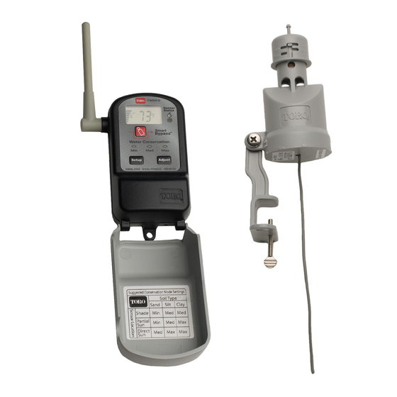
Receiver Module Features 1– Setup Button–Accesses the sensor system operating features. 2– Adjust Button–Scrolls through and selects settings within the system operating features. 3– Mast Antenna–Adjusts easily for best signal reception. 4– Digital Display–High-resolution LCD screen provides visual reference for sensor system operating features. 5–... -
Page 7: Installing The Receiver Module
Installing the Receiver Module Important: Installation of this product must comply with national and local building and electrical codes. For assistance, contact a professional irrigation system contractor in your area. The receiver module is suitable for either indoor or outdoor installation. Select a location next to the controller that provides the following conditions: •... - Page 8 Connecting the Receiver Wires CAUTION: The receiver requires continuous 24 Vac power for operation. Connecting to 110 Vac or higher will result in irreparable damage. Ensure power to the controller has been removed prior to connecting the receiver wires. The sensor system is designed to work with most makes and models of irrigation controllers. •...
- Page 9 For a normally-open sensor, attach the Yellow wire to the remaining sensor terminal. Tape back the Brown wire. See Figure 3. 4. Attach the Red wires to the 24 Vac terminals. Important Most controllers with sensor connections also provide a control switch to bypass sensor operation if necessary.
-
Page 10: Initial Sensor System Test
The Sensor Status indicator will illuminate (Figure 8), the Antenna symbol will flash and the signal bars will appear. Release the test spindle. The TWRS receiver will display alternating boxes (Figure 9) and the TWRFS receiver will display the current air temperature (Figure 10). -
Page 11: Sensor Module Features
Sensor Module Features 1– Rain Threshold Adjustment–Adjusts the rain sensor to accumulate 1/8", 1/4", 1/2" or 3/4" (3mm, 6mm,12mm or 19mm) of rainfall before signaling the receiver to hold watering. (Factory default setting 1/4" (6mm). 2– Sensor Test Spindle–Pressed to manually activate the sensor for setup and test procedures. -
Page 12: Installing The Sensor Module
Installing the Sensor Module Choosing the right installation site for the sensor module is the key to getting the maximum benefit from your sensor system. Select a sensor installation site that provides the following conditions: • Unobstructed exposure to rainfall–away from overhangs, tree branches, etc. •... - Page 13 3. Adjust the Rain sensor to the preferred rainfall threshold activation point. The settings are indicated in 1/8", 1/4", 1/2" and 3/4" on one side of the cap, and 3mm, 6mm, 12mm and 19mm on the other. First, turn the cap to align the stationary pin with the vertical slot.
- Page 14 A pipe-mount adapter is provided to enable sensor installation on a secured section of 1/2" (13mm) diameter Schedule 40 PVC pipe. Note: Metal pipe or conduit may interfere with radio signal transmission and is not recommended. Remove and replace the Quick Clip bracket with the pipe-mount adapter. Ensure the friction washer is installed between the adapter and housing tabs as shown in Figure 14.
-
Page 15: Freeze Sensor Site Selection
CAUTION: The rain/freeze sensor module should be regularly inspected for damage and manually tested to ensure proper operation. The Toro Wireless Rain/Freeze sensor system is NOT intended for farm/crop freeze protection and must not be used for this purpose. Important: Visual checks and prudent manual watering suspension must be used in conjunction with any freeze sensor. -
Page 16: Set Temperature Activation Threshold
Set Temperature Activation Threshold (TWRFS models only) The freeze sensor temperature activation threshold is adjustable from 35°F to 45°F or 2°C to 7°C. When the air temperature reaches the threshold setting, the freeze sensor activates the receiver. The Freeze Sensor Status indicator will turn on. The sensor system will return to the Monitor mode when the outside air temperature rises above the sensor threshold temperature. -
Page 17: Water Conservation Feature
Water Conservation Feature – By simply choosing the Minimum, Medium or Maximum conservation level that corresponds to your landscape’s soil type and the sensor location, a dry-out period, adjusted for actual rainfall duration, is inserted after the sensor system resets to delay the resumption of automatic watering. Each Water Conservation level represents a baseline value that is automatically adjusted to compensate for rainfall duration. -
Page 18: Smart Bypass Feature
Smart Bypass Feature Pressing the Smart Bypass button switches an active sensor system Off and places it in the Bypass mode. When the sensor is bypassed, the controller resumes automatic watering operations as scheduled. The Sensor Status indicator and the Bypass display prompt will flash to indicate when the sensor system is in the Bypass mode. -
Page 19: Signal Strength Display Feature
Signal Strength Display This feature displays sensor signal strength on a digital scale ranging from 0.0 to 10.2 1. Press the Setup button as needed to display the antenna icon and the digital readout. The display will indicate the strength of the last received signal. -
Page 20: Dry Out Feature
Dry Out Feature The Dry Out feature is provided to override the Water Conservation baseline level, allowing the dry-out delay period to be set in 0.5-day increments from 0.5 to 4.0 days. Note: Before using the Dry Out feature, allow the sensor system to normalize by cycling through rain and/or freeze activation several times. - Page 21 Loss of communication If the sensor system does not communicate within a 24-hour period, it will remain in its current state (Active or Monitor). To alert you to this condition, the Attention Required symbol will be displayed. The Antenna symbol and current air temperature (TWRFS only) will be flashing and the signal bar indicator will be cleared.
-
Page 22: Turn Receiver Module Off And On
Turn the Receiver Module Off and On 1. To turn the receiver module Off, press and hold the Adjust button until two dashes are displayed (approximately 5 seconds), then release. 2. To turn the receiver On, press the Setup button two times. The receiver will return to the normal display mode within approximately 10 seconds. -
Page 23: Sensor Module Battery Replacement
Sensor Module Battery Replacement 1. Unscrew and remove the bottom cap from the sensor housing. 2. Grasping the edges of the circuit board assembly, carefully slide the circuit board assembly out of the housing. 3. Remove the battery cover and batteries. 4. -
Page 24: Troubleshooting
If you encounter problems at any point in the installation process, or the components do not seem to function properly, try the Troubleshooting procedures first. If the problem is not listed or the remedy does not resolve the problem, call the Toro Irrigation help line at 1-800-664-4740. Solving Reception Problems The Wireless RainSensor has an operating range of 500' (152.4m) LOS (Line-of-Site). - Page 25 The receiver display is blank. • Check the 24 Vac power connections. The red power wires from the receiver must be connected to the controller’s 24 Vac power source. Make sure the power wires are not connected to the station or pump/master valve terminals. These terminals only provide 24 Vac power when the controller is operating the sprinkler zones.
-
Page 26: Specifications
Specifications Models: TWRS (Wireless RainSensor) and TWRFS (Wireless Rain/Freeze Sensor) Wireless Communication Range: 500' (152.4m) LOS (line-of site) Sensor Type: Industry-standard hygroscopic disc stack with adjustable rainfall sensitivity Sensor Module Batteries: (2) 3V cells - CR2032 (or equivalent) Average Battery Life: 5 years Operating Temperature Range: -20°F to 120°F (-29°C to 49°C) -
Page 27: Warranty Information
This warranty gives you specific legal rights and you may have other rights which vary from state to state. The Toro Wireless RainSensor series is covered by this warranty for a period of five years from the date of installation. -
Page 28: Electromagnetic Compatibility
Important: Changes or modifications to this unit, not expressly approved by the party responsible for compliance, could void the authority to operate the equipment. FCC ID: OF7TWRS IC: 3575A-TWRS © 2005 The Toro Company, Irrigation Division Form Number 373-0332 Rev. A...