Table of Contents
Advertisement
Quick Links
Advertisement
Table of Contents

Related Manuals for KTM 690 Enduro R 2019


Summary of Contents for KTM 690 Enduro R 2019
- Page 1 OWNER'S MANUAL 2019 690 Enduro R Art. no. 3213909en...
- Page 3 DEAR KTM CUSTOMER Congratulations on your decision to purchase a KTM motorcycle. You are now the owner of a state-of-the-art DEAR KTM CUSTOMER sports vehicle that will continue giving you pleasure for a long time if you maintain it properly. We wish you good and safe riding at all times! Enter the serial numbers of your vehicle below.
- Page 4 Reproduction, even in part, as well as copying of all kinds, is permitted only with the express written permission of the copyright owner. ISO 9001(12 100 6061) KTM applies quality assurance processes that lead to the highest possible product quality as defined in the ISO 9001 international quality management standard. Issued by: TÜV Management Service KTM Sportmotorcycle GmbH Stallhofnerstraße 3...
-
Page 5: Table Of Contents
TABLE OF CONTENTS VIEW OF VEHICLE ........20 TABLE OF CONTENTS MEANS OF REPRESENTATION ...... 9 View of vehicle, front left (example) ... 20 Symbols used ........9 View of vehicle, rear right Formats used........10 (example)........22 SAFETY ADVICE.......... 11 SERIAL NUMBERS ........ - Page 6 TABLE OF CONTENTS 6.12 Overview of indicator lamps ....35 PREPARING FOR USE......... 52 6.13 Seat unlocking......... 37 Advice on preparing for first use ..52 6.14 Grab handles ........37 Running in the engine ...... 54 6.15 Passenger foot pegs ......38 Loading the vehicle ......
- Page 7 TABLE OF CONTENTS 10.2 Adjusting the compression damping 11.7 Checking the steering head bearing of the fork ........84 play ..........97 10.3 Adjusting the rebound damping of 11.8 Adjusting the steering head bearing the fork........... 86 play ..........98 10.4 Compression damping of the shock 11.9...
- Page 8 TABLE OF CONTENTS 11.28 Installing the engine guard ..... 125 13.3 Removing the rear wheel ..... 157 13.4 Installing the rear wheel ....159 12 BRAKE SYSTEM ........126 13.5 Checking the rear hub damping 12.1 Anti-lock braking system (ABS) ..126 rubber pieces ......
- Page 9 TABLE OF CONTENTS 14.13 Changing the combination 17.2 Changing the engine oil and oil instrument battery......193 filter, cleaning the oil screens ..216 14.14 USB socket ........196 17.3 Adding engine oil ......222 14.15 ACC1 and ACC2......196 18 CLEANING, CARE ........
- Page 10 TABLE OF CONTENTS 21.8 Shock absorber ......248 21.9 Chassis tightening torques ....249 22 SUBSTANCES .......... 256 23 AUXILIARY SUBSTANCES ......259 24 STANDARDS ..........261 25 INDEX OF SPECIAL TERMS ....... 262 26 LIST OF ABBREVIATIONS......263 27 LIST OF SYMBOLS........264 27.1 Red symbols........
-
Page 11: Means Of Representation 1
All work marked with this symbol requires specialist knowledge and technical understanding. In the interest of your own safety, have these jobs performed by an authorized KTM workshop! Your motorcycle will be optimally cared for there by specially trained experts using the auxiliary tools required. -
Page 12: Formats Used
1 MEANS OF REPRESENTATION Indicates a voltage measurement. Indicates a current measurement. Indicates the end of an activity, including potential rework. Formats used The typographical formats used in this document are explained below. Proprietary name Indicates a proprietary name. Name ®... -
Page 13: Safety Advice 2
Info This vehicle is only authorized for operation on public roads in its homologated version. When used in a dusty environment, it may be necessary to use air filter protection. Your authorized KTM dealer will be happy to advise you. -
Page 14: Degrees Of Risk And Symbols
2 SAFETY ADVICE Info Various information and warning labels are attached in prominent locations on the product described. Do not remove any information or warning labels. If they are missing, you or others may not recognize dangers and may therefore be injured. Degrees of risk and symbols Danger Identifies a danger that will immediately and invariably lead to fatal or serious permanent injury if the... -
Page 15: Tampering Warning
SAFETY ADVICE 2 Tampering warning Tampering with the noise control system is prohibited. Federal law prohibits the following acts or the causing thereof: 1 The removal or rendering inoperative by any person other than for purposes of servicing, repair, or replace- ment, of any device or element of design incorporated into any new vehicle for the purpose of noise control prior to its sale or delivery to the ultimate purchaser or while it is in use, or 2 the use of the vehicle after such device or element of design has been removed or rendered inoperative by any... -
Page 16: Protective Clothing
An appropriate driver's license is needed to drive the vehicle on public roads. Have malfunctions that impair safety promptly eliminated by an authorized KTM workshop. Adhere to the information and warning labels on the vehicle. -
Page 17: Work Rules
SAFETY ADVICE 2 In the interest of your own safety, KTM recommends that you only operate the vehicle while wearing protective clothing. Work rules Special tools are necessary for certain tasks. The tools are not a component of the vehicle, but can be ordered using the number in parentheses. -
Page 18: Owner's Manual
The Owner's Manual is an important component of the vehicle and must be handed over to the new owner if the vehicle is sold. The Owner's Manual is also available for download from your authorized KTM dealer and on the KTM website. International KTM Website: http://www.ktm.com... -
Page 19: Important Notes 3
Manufacturer and implied warranty The work specified in the service schedule may only be performed in an authorized KTM workshop and must be recorded in both the Service & Warranty Booklet and in the KTM Dealer.net, otherwise any warranty coverage will become void. -
Page 20: Service
Please follow the instructions in the text. Customer service Your authorized KTM dealer will be happy to answer any questions you may have on your vehicle and KTM. - Page 21 IMPORTANT NOTES 3 A list of authorized KTM dealers can be found on the KTM website. International KTM Website: http://www.ktm.com...
-
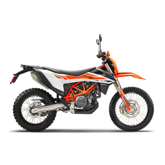
Page 22: View Of Vehicle
4 VIEW OF VEHICLE View of vehicle, front left (example) S03366-10... - Page 23 VIEW OF VEHICLE 4 Hand brake lever ( p. 27) Clutch lever ( p. 27) Grab handles ( p. 37) Fuel tank filler cap Passenger foot pegs ( p. 38) Seat unlocking ( p. 37) Compression damping of the shock absorber ( p.
-
Page 24: View Of Vehicle, Rear Right (Example)
4 VIEW OF VEHICLE View of vehicle, rear right (example) S03367-10... - Page 25 VIEW OF VEHICLE 4 Ignition and steering lock ( p. 34) Fork compression adjuster Light switch ( p. 29) Turn signal switch ( p. 29) Horn button ( p. 28) Combination switch ( p. 32) Overview of indicator lamps ( p.
-
Page 26: Serial Numbers
5 SERIAL NUMBERS Vehicle identification number The vehicle identification number is stamped on the right side of the steering head. 401945-10 Type label The type label is located on the right side of the frame. H01049-10... -
Page 27: Key Number
SERIAL NUMBERS 5 Key number can be found on the KEYCODECARD. The key number Info You need the key number to order a spare key. Keep the KEYCODECARD in a safe place. 402241-10 Engine number The engine number is stamped on the left side of the engine under the engine sprocket. -
Page 28: Fork Part Number
5 SERIAL NUMBERS Fork part number The fork part number is stamped on the inner side of the fork stub. 401947-10 Shock absorber article number The shock absorber article number is on the left side of the shock absorber. 402025-10... -
Page 29: Controls 6
CONTROLS 6 Clutch lever Clutch lever is fitted on the handlebar on the left. The clutch is activated hydraulically and adjusts itself automati- cally. S03355-10 Hand brake lever The hand break lever is fitted on the right side of the handle- bar. -
Page 30: Throttle Grip
6 CONTROLS Throttle grip The throttle grip is fitted on the right side of the handlebar. S03357-10 Horn button The horn button is fitted on the left side of the handlebar. Possible states • Horn button in neutral position pressed – The horn is operated in this posi- •... -
Page 31: Light Switch
CONTROLS 6 Light switch The light switch is fitted on the left side of the handlebar. Possible states Low beam on – Light switch is turned downward. In this position, the low beam and tail light are switched High beam on – Light switch is turned upward. In this position, the high beam and tail light are switched on. -
Page 32: Emergency Off Switch
6 CONTROLS To switch off the turn signal light, press the turn signal switch towards the switch case. Emergency OFF switch The emergency OFF switch is fitted on the right side of the handlebar. Possible states Emergency OFF switch off – In this position, the igni- tion circuit is interrupted, a running engine stops, and the engine cannot be started. -
Page 33: Electric Starter Button
CONTROLS 6 Electric starter button The electric starter button is fitted on the right side of the handlebar. Possible states • Electric starter button in basic position is pressed – In this position, the • Electric starter button starter motor is actuated. S03359-11 ABS button The ABS button... -
Page 34: Combination Switch
6 CONTROLS 6.10 Combination switch The combination switch is fitted on the left side of the handlebar. Possible states ROAD – Drive mode ROAD and traction control are acti- vated when LED 1 lights up. ROAD without TC – When LEDs 1 and TC light up, drive mode ROAD is active and traction control is deactivated. - Page 35 Each time the ignition is switched on, all three switch LEDs light up for a function check. If all three LEDs light up during operation, an error has been detected by the engine control unit. Contact an authorized KTM workshop immediately. H02887-01...
-
Page 36: Ignition And Steering Lock
6 CONTROLS 6.11 Ignition and steering lock The ignition and steering lock is located in front of the seat. Possible states Ignition off – In this position, the ignition circuit is interrupted, a running engine stops, and a non-running engine will not start. The ignition key can be removed. -
Page 37: Overview Of Indicator Lamps
Malfunction indicator lamp lights up orange – The OBD has detected an error in the vehicle electronics. Come safely to a halt, and contact an authorized KTM workshop. The coolant temperature warning lamp lights up red –... - Page 38 71) is not active. If the TC indicator lamp and both drive mode lamps light up at same time, an error as been detected. Contact an authorized KTM workshop. The TC indicator lamp flashes if the MTC actively engages.
-
Page 39: Seat Unlocking
CONTROLS 6 6.13 Seat unlocking The loop unlocks the seat. S03336-10 6.14 Grab handles The grab handles are used for moving the motorcycle around. If you carry a passenger, the passenger can hold onto the grab handles during the trip. S03277-10... -
Page 40: Passenger Foot Pegs
6 CONTROLS 6.15 Passenger foot pegs The passenger foot pegs can be folded up and down. Possible states Passenger foot pegs folded up – For operation without a pas- • senger. Passenger foot pegs folded down – For operation with a pas- •... -
Page 41: Foot Brake Lever
CONTROLS 6 The gear positions can be seen in the photograph. The neutral or idle position is between the first and second gears. 401950-11 6.17 Foot brake lever Foot brake lever is located in front of the right footrest. The rear brake is engaged with the foot brake lever. 401956-10... -
Page 42: Side Stand
6 CONTROLS 6.18 Side stand The side stand is located on the left side of the vehicle. The side stand is used for parking the motorcycle. Info The side stand must be folded up during motorcycle use. The side stand is coupled with the safety starting system – see the riding instructions. -
Page 43: Opening Fuel Tank Filler Cap
CONTROLS 6 6.19 Opening fuel tank filler cap Danger Fire hazard Fuel is highly flammable. The fuel in the fuel tank expands when warm and can escape if overfilled. – Do not refuel the vehicle in the vicinity of open flames or lit cigarettes. –... - Page 44 6 CONTROLS Note Environmental hazard Improper handling of fuel is a danger to the environment. – Do not allow fuel to enter the groundwater, the soil, or the sewage system. – Lift cover of fuel tank filler cap and insert the ignition key. –...
-
Page 45: Closing The Fuel Tank Filler Cap
CONTROLS 6 6.20 Closing the fuel tank filler cap – Put the fuel tank filler cap back on and turn the ignition key 90° clockwise. – Remove the ignition key and fold down the cover. S03279-10 6.21 Combination instrument 6.21.1 Overview Overview of indicator lamps ( p. -
Page 46: Activation
6 CONTROLS 6.21.2 Activation Activating combination instrument The combination instrument is activated when one of the buttons is pressed or an impulse comes from the wheel speed sensor. S02156-10 6.21.3 Messages on the combination instrument Possible states Battery voltage of the combination instrument – The battery voltage of the combination instrument is too low. -
Page 47: Setting The Combination Instrument
CONTROLS 6 6.21.4 Setting the combination instrument Condition The motorcycle is stationary. – Press and hold both buttons for 3 – 5 seconds. The Setup menu is displayed. The UNIT display flashes. Info Combination settings can be made once the set-up menu is active. -
Page 48: Setting The Clock
6 CONTROLS – Press and hold both buttons for 3 – 5 seconds. The Setup menu is displayed. The UNIT display flashes. – Change the display mode from KM/H to M/H or from M/H to KM/H using the left or right button. –... -
Page 49: Setting The Service Display
CONTROLS 6 – Set the time using the left and the right button. Resetting the time – Press the left button. The value decreases. Advancing the time – Press the right button. The value increases. – Wait for 5 seconds. The setting is adopted and the combination instru- 401912-01 ment automatically changes to the next menu item. - Page 50 6 CONTROLS The value decreases. Extending the service interval – Press the right button. The value increases. Switching off the service interval display – Press and hold the left button. off appears in the display. 401914-01...
-
Page 51: Speed, Time, And Dst Distance 1
CONTROLS 6 6.21.8 Speed, time, and DST distance 1 – Press one of the buttons until DST appears on the combination instrument. KM/H or M/H shows the speed. shows the time. DST shows the distance since the last reset, such as between two refueling stops. -
Page 52: Speed, Time, And Dst2 Distance 2
6 CONTROLS 6.21.9 Speed, time, and DST2 distance 2 – Press one of the buttons until DST2 appears on the combina- tion instrument. KM/H or M/H shows the speed. shows the time. DST2 shows the distance 2 since the last reset, such as between two refueling stops. -
Page 53: 6.21.10 Avg Average Speed, Art Operating Hours, And Odo Total Distance Covered
CONTROLS 6 6.21.10 AVG average speed, ART operating hours, and ODO total distance covered – Press one of the buttons until AVG, ART and ODO appear on the combination instrument. AVG shows the average speed since the last reset. ART shows the operating hours. ODO shows the total distance covered. -
Page 54: Preparing For Use
Make sure that only tires with a similar tire tread pattern are fitted to the front and rear wheel. Warning Danger of accidents Non-approved or non-recommended tires and wheels impact the handling character- istic. – Only use tires/wheels approved by KTM with the corresponding speed index. - Page 55 When using your vehicle, remember that others may feel disturbed by excessive noise. – Make sure that the pre-sales inspection work has been carried out by an authorized KTM workshop. You receive a delivery certificate and the Service & Manufacturer Warranty Booklet at vehicle handover.
-
Page 56: Running In The Engine
7 PREPARING FOR USE – Get used to handling the motorcycle in a suitable area before making a longer trip. Try also to ride as slowly as possible and in a standing position to get a better feel for the motorcycle. –... -
Page 57: Loading The Vehicle
PREPARING FOR USE 7 Loading the vehicle Warning Danger of accidents Total weight and axle loads influence the handling characteristic. The total weight consists of: motorcycle ready for operation and with a full tank, driver and passenger with protective clothing and helmet, and luggage. –... - Page 58 7 PREPARING FOR USE Warning Danger of accidents Luggage which has slipped impairs visibility. If the tail light is covered, you are less visible to traffic behind you, especially when it is dark. – Check that your luggage is fixed properly at regular intervals. Warning Danger of accidents A high payload alters the handling characteristic and increases the stopping distance.
- Page 59 PREPARING FOR USE 7 Guideline Maximum permissible overall weight 350 kg (772 lb.) Maximum permissible front axle load 150 kg (331 lb.) Maximum permissible rear axle load 200 kg (441 lb.)
-
Page 60: Riding Instructions
8 RIDING INSTRUCTIONS Checks and maintenance measures when preparing for use Info Before every trip, check the condition of the vehicle and ensure that it is roadworthy. The vehicle must be in perfect technical condition when it is being operated. –... -
Page 61: Starting The Vehicle
RIDING INSTRUCTIONS 8 Starting the vehicle Danger Danger of poisoning Exhaust gases are toxic and inhaling them may result in unconsciousness and death. – Always make sure there is sufficient ventilation when running the engine. – Use effective exhaust extraction when starting or running the engine in an enclosed space. Caution Danger of accidents Electronic components and safety devices will be damaged if the 12-V battery is dis- charged or missing. - Page 62 8 RIDING INSTRUCTIONS – Turn the emergency OFF switch to the position – Switch on the ignition by turning the ignition key to the posi- tion After you switch on the ignition, you can hear the fuel pump working for about two seconds. The function check of the combination instrument is run at the same time.
- Page 63 Take the weight off the side stand and swing it back up with your foot as far as it will go. Switching off the ABS KTM recommends riding with ABS at all times. However, situa- tions may arise in which ABS is not advantageous.
-
Page 64: Starting Off
8 RIDING INSTRUCTIONS Condition The motorcycle is stationary. Vehicle speed before stopping: ≥ 5 km/h (≥ 3.1 mph) Note Voiding of the government approval for road use and the insurance coverage If the ABS is switched off com- pletely, the vehicle's approval for road use is invali- dated. -
Page 65: Shifting, Riding
RIDING INSTRUCTIONS 8 Shifting, riding Warning Danger of accidents Abrupt load alterations can cause the vehicle to get out of control. – Avoid abrupt load alterations and sudden braking actions. – Adapt your speed to the road conditions. Warning Danger of accidents If you change down at high engine speed, the rear wheel blocks and the engine races. - Page 66 8 RIDING INSTRUCTIONS Warning Risk of injury The passenger may fall from the motorcycle if they conduct themselves incorrectly. – Ensure that the passenger sits correctly on the passenger seat, places his or her feet on the passenger foot pegs and holds on to the rider or the grab handles. –...
- Page 67 RIDING INSTRUCTIONS 8 Warning Danger of accidents Total weight and axle loads influence the handling characteristic. The total weight consists of: motorcycle ready for operation and with a full tank, driver and passenger with protective clothing and helmet, and luggage. – Do not exceed the maximum permissible overall weight or the axle loads.
- Page 68 Check and, if necessary, correct the coolant level on the cooling system while it is in a cooled state. Info If unusual noises arise during operation, stop immediately, switch off the engine, park the vehicle prop- erly, and contact an authorized KTM workshop. – Shift into a higher gear when conditions allow (incline, road situation, etc.).
- Page 69 – If the oil pressure warning lamp lights up, stop immediately, taking care not to endanger yourself or other road users in the process, and switch off the engine. Contact an authorized KTM workshop. – If the malfunction indicator lamp...
- Page 70 8 RIDING INSTRUCTIONS Condition The quickshifter + (optional) is enabled. – Quickshifter + allows you to shift up in the speed range shown without pulling the clutch lever. Guideline Minimum speed before gear change First gear to second 30 km/h (18.6 mph) gear Second gear to third 40 km/h (24.9 mph)
- Page 71 RIDING INSTRUCTIONS 8 Guideline Maximum speed before gear change Sixth gear to fifth gear 165 km/h (102.5 mph) Fifth gear to fourth 145 km/h (90.1 mph) gear Fourth gear to third 120 km/h (74.6 mph) gear Third gear to second 90 km/h (55.9 mph) gear Second gear to first...
-
Page 72: Quickshifter + (Optional)
8 RIDING INSTRUCTIONS Quickshifter + (optional) If the quickshifter + (optional) is activated, you can shift up and down without actuating the clutch. Because there is no need to close the throttle grip, uninterrupted gear shifts are possible. The quickshifter + uses the shifter shaft position to check whether or not a shift should be initiated, and sends a corresponding signal to the engine control. -
Page 73: Motorcycle Traction Control (Mtc)
RIDING INSTRUCTIONS 8 Motorcycle traction control (MTC) The motorcycle traction control (MTC) lowers the engine torque in case of loss of traction in the rear wheel. Info When motorcycle traction control is switched off, the rear wheel may spin during strong acceleration and on surfaces with low grip, resulting in a risk of crashing. -
Page 74: Applying The Brakes
Danger of accidents A spongy pressure point on the front or rear brake reduces braking efficiency. – Check the brake system and do not continue riding until the problem is eliminated. (Your authorized KTM workshop will be glad to help.) Warning Danger of accidents The brake system fails in the event of overheating. - Page 75 RIDING INSTRUCTIONS 8 Warning Danger of accidents ABS may increase the stopping distance in certain situations. – Adjust application of the brakes to the respective riding situation and riding surface conditions. Warning Danger of accidents Excessively forceful application of the brakes blocks the wheels. The ABS effectiveness is only ensured if it is switched on.
-
Page 76: Stopping, Parking
8 RIDING INSTRUCTIONS – Use the braking effect of the engine on long downhill stretches. Change down one or two gears, but do not over-rev the engine. You will have to apply the brakes far less frequently as a result and the brake system will not overheat. - Page 77 RIDING INSTRUCTIONS 8 Note Fire hazard Hot vehicle components pose a fire hazard and explosion risk. – Do not park the vehicle near to materials which are highly flammable or explosive. – Allow the vehicle to cool down before covering it. –...
-
Page 78: Transport
8 RIDING INSTRUCTIONS Transport Note Danger of damage The parked vehicle can roll away or fall over. – Park the vehicle on a firm and level surface. Note Fire hazard Hot vehicle components pose a fire hazard and explosion risk. – Do not park the vehicle near to materials which are highly flammable or explosive. –... -
Page 79: Refueling
RIDING INSTRUCTIONS 8 8.10 Refueling Danger Fire hazard Fuel is highly flammable. The fuel in the fuel tank expands when warm and can escape if overfilled. – Do not refuel the vehicle in the vicinity of open flames or lit cigarettes. –... - Page 80 In some countries and regions, the available fuel quality and cleanliness may not be sufficient. This will result in problems with the fuel system. – Refuel only with clean fuel that meets the specified standards. (Your authorized KTM workshop will be glad to help.) Note Environmental hazard Improper handling of fuel is a danger to the environment.
- Page 81 RIDING INSTRUCTIONS 8 – Switch off the engine. – Open fuel tank filler cap. ( p. 41) – Fill the fuel tank with fuel up to level Guideline 20 mm (0.79 in) Dimension Total fuel tank 13.5 l Super unleaded capacity, approx.
-
Page 82: Service Schedule
Different service intervals may apply in your country, depending on the local operating conditions. Individual service intervals and scopes may change in the course of technical developments. The most up-to-date service schedule can always be found on KTM Dealer.net. Your authorized KTM dealer will be happy to advise you. - Page 83 SERVICE SCHEDULE 9 after every sporting use Every two years Every year every 20,000 km (12,400 mi) every 10,000 km (6,200 mi) after 1,000 km (620 mi) ● Change the front brake fluid. ● Change the rear brake fluid. ● Change the hydraulic clutch fluid.
- Page 84 Final check: Check the vehicle is roadworthy and take a test ride. ○ ● ● ● ● ● Read out the fault memory using the KTM diagnostics tool after a test ride. ○ ● ● ● ● ● Make the service entry in KTM Dealer.net and in the Service & Manufacturer War- ranty Booklet.
-
Page 85: Recommended Work
SERVICE SCHEDULE 9 Recommended work after every sporting use Every four years Every year every 30,000 km (18,600 mi) every 10,000 km (6,200 mi) after 1,000 km (620 mi) ● Check the frame. ● Check the link fork. ● ● Check the link fork bearing for play. -
Page 86: 10 Tuning The Chassis
10 TUNING THE CHASSIS 10.1 Fork/shock absorber The fork and the shock absorber offer many options for adapting the chassis to the riding style and the payload. Info The recommendations for the suspension setting are shown in table . The table is located on the underside of the front rider's seat. - Page 87 TUNING THE CHASSIS 10 – Turn white adjusting screw clockwise as far as it will go. Info Adjusting screw is located at the upper end of the left fork leg. The compression damping is located in left fork leg COMP (white adjusting screw). The rebound damping is located in right fork leg REB (red adjusting screw).
-
Page 88: Adjusting The Rebound Damping Of The Fork
10 TUNING THE CHASSIS 10.3 Adjusting the rebound damping of the fork Info The hydraulic rebound damping determines the fork suspension behavior. – Turn red adjusting screw clockwise as far as it will go. Info Adjusting screw is located at the upper end of the right fork leg. -
Page 89: Compression Damping Of The Shock Absorber
Risk of injury Parts of the shock absorber will move around if the shock absorber is detached incorrectly. The shock absorber is filled with highly compressed nitrogen. – Please follow the description provided. (Your authorized KTM workshop will be glad to help.) - Page 90 10 TUNING THE CHASSIS Info The effect of the low-speed setting can be seen in slow to normal compression of the shock absorber. – Turn adjusting screw clockwise with a screwdriver as far as the last perceptible click. Info Do not loosen fitting –...
-
Page 91: Adjusting The High-Speed Compression Damping Of The Shock Absorber
The shock absorber is filled with highly compressed nitrogen. – Please follow the description provided. (Your authorized KTM workshop will be glad to help.) Info The effect of the high-speed setting can be seen in fast compression of the shock absorber. -
Page 92: Adjusting The Rebound Damping Of The Shock Absorber
Risk of injury Parts of the shock absorber will move around if the shock absorber is detached incorrectly. The shock absorber is filled with highly compressed nitrogen. – Please follow the description provided. (Your authorized KTM workshop will be glad to help.) - Page 93 TUNING THE CHASSIS 10 – Turn adjusting screw clockwise up to the last perceptible click. – Turn counterclockwise by the number of clicks corresponding to the shock absorber type. Guideline Rebound damping Comfort 25 clicks Standard 20 clicks 100247-10 Sport 10 clicks Full payload 10 clicks...
-
Page 94: 11 Service Work On The Chassis
11 SERVICE WORK ON THE CHASSIS 11.1 Raising the motorcycle with a lift stand Note Danger of damage The parked vehicle can roll away or fall over. – Park the vehicle on a firm and level surface. – Use the motor guard underneath the motor to raise the vehicle. Neither wheel is in contact with the ground. -
Page 95: Cleaning The Dust Boots Of The Fork Legs
SERVICE WORK ON THE CHASSIS 11 – Remove the motorcycle from the lift stand and rest it on side stand – Remove the lift stand. 401943-10 11.3 Cleaning the dust boots of the fork legs Preparatory work – Raise the motorcycle with a lift stand. ( p. - Page 96 11 SERVICE WORK ON THE CHASSIS Warning Danger of accidents Oil or grease on the brake discs reduces the braking effect. – Always keep the brake discs free of oil and grease. – Clean the brake discs with brake cleaner when nec- essary.
-
Page 97: Removing Fork Protector
SERVICE WORK ON THE CHASSIS 11 11.4 Removing fork protector – Remove screws and take off the clamp. – Remove screws on the left fork leg. Take off the fork pro- tector. – Remove screws on the right fork leg. Take off the fork pro- tector. -
Page 98: Bleeding The Fork Legs
11 SERVICE WORK ON THE CHASSIS Guideline Remaining screws, 10 Nm (7.4 lbf ft) chassis 11.6 Bleeding the fork legs Preparatory work – Raise the motorcycle with a lift stand. ( p. 92) Main work – Release bleeder screws Any excess pressure escapes from the interior of the fork. –... -
Page 99: Checking The Steering Head Bearing Play
Danger of accidents Incorrect steering head bearing play impairs the handling characteristic and dam- ages components. – Correct incorrect steering head bearing play immediately. (Your authorized KTM workshop will be glad to help.) Info If the vehicle is operated for a lengthy period with play in the steering head bearing, the bearings and the bearing seats in the frame can become damaged over time. -
Page 100: Adjusting The Steering Head Bearing Play
11 SERVICE WORK ON THE CHASSIS It must be possible to move the handlebar easily over the entire steering range. There should be no detectable detent positions. » If detent positions are detected: – Adjust the steering head bearing play. p. -
Page 101: Removing The Seat
SERVICE WORK ON THE CHASSIS 11 – Tighten screws Guideline Screw, top triple 17 Nm (12.5 lbf ft) clamp – Tighten screw Guideline Screw, steering stem 20 Nm (14.8 lbf ft) Finishing work – Check the steering head bearing play. ( p. -
Page 102: Mounting The Seat
11 SERVICE WORK ON THE CHASSIS 11.10 Mounting the seat S03282-10 – Hook the seat using holding lugs on to bushings , lower the seat at the rear and push it forward. – Push locking pin into lock housing and push the back of the seat down until the locking pin locks in place with an audible click. -
Page 103: Storing The Tool Set
SERVICE WORK ON THE CHASSIS 11 Main work – Remove the left side cover from the rubber bushing in area – Remove the left side cover upwards from the bushing in area – Take off the left side cover from the front. –... - Page 104 11 SERVICE WORK ON THE CHASSIS Main work – Store the tool set in the tool set compartment. – Position the left side cover using holding lugs on bushings and push towards the rear and, in the rear section, down- ward.
-
Page 105: Take Off The Side Cover
SERVICE WORK ON THE CHASSIS 11 11.13 Take off the side cover Preparatory work – Remove the seat. ( p. 99) Main work – Remove the left side cover from the rubber bushing in area – Remove the left side cover upwards from the bushing in area –... -
Page 106: Mounting Side Cover
11 SERVICE WORK ON THE CHASSIS 11.14 Mounting side cover Main work – Position the left side cover using holding lugs on bushings and push towards the rear and, in the rear section, down- ward. – Press the left side cover into the rubber bushing in area –... -
Page 107: Removing The Front Fender
SERVICE WORK ON THE CHASSIS 11 11.15 Removing the front fender Preparatory work – Remove the headlight mask with the headlight. ( p. 186) Main work – Remove screws – Remove screws and take off the fender. S03291-10... -
Page 108: Installing The Front Fender
11 SERVICE WORK ON THE CHASSIS 11.16 Installing the front fender Main work – Position the front fender. Mount and tighten screws Guideline Remaining screws, 10 Nm (7.4 lbf ft) chassis – Mount and tighten screws Guideline Remaining screws, 10 Nm (7.4 lbf ft) S03292-10 chassis Finishing work... - Page 109 SERVICE WORK ON THE CHASSIS 11 Main work – Remove screws – Remove the upper part of the air filter box S03338-10 Note Engine damage Unfiltered intake air has a negative effect on the service life of the engine. Dust and dirt will enter the engine without an air filter. –...
-
Page 110: Installing The Air Filter
11 SERVICE WORK ON THE CHASSIS 11.18 Installing the air filter Main work – Clean the air filter box. – Mount air filter Info The air filter must lie flush against the air filter box along the entire sealing surface If the air filter is not mounted correctly, dust and dirt may enter the engine and result in damage. -
Page 111: Checking The Chain For Dirt
SERVICE WORK ON THE CHASSIS 11 11.19 Checking the chain for dirt – Check the chain for heavy soiling. » If the chain is very dirty: – Clean the chain. ( p. 109) 400678-01 11.20 Cleaning the chain Warning Danger of accidents Lubricants on the tires reduces the road grip. –... - Page 112 11 SERVICE WORK ON THE CHASSIS Note Environmental hazard Hazardous substances cause environmental damage. – Dispose of oils, grease, filters, fuel, cleaning agents, brake fluid, etc., correctly and in compliance with the applicable regulations. Info The service life of the chain depends largely on its maintenance. Preparatory work –...
-
Page 113: Checking The Chain Tension
SERVICE WORK ON THE CHASSIS 11 11.21 Checking the chain tension Warning Danger of accidents Incorrect chain tension damages components and results in accidents. If the chain is tensioned too much, the chain, engine sprocket, rear sprocket, transmission and rear wheel bearings wear more quickly. Some components may break if overloaded. If the chain is too loose, the chain may fall off the engine sprocket or the rear sprocket. - Page 114 11 SERVICE WORK ON THE CHASSIS – Place the motorcycle onto the side stand. – Shift the transmission to neutral position. – Push the chain upward at a distance from the chain slid- ing guard and determine chain tension Info Top chain section must be taut.
-
Page 115: Adjusting The Chain Tension
SERVICE WORK ON THE CHASSIS 11 11.22 Adjusting the chain tension Warning Danger of accidents Incorrect chain tension damages components and results in accidents. If the chain is tensioned too much, the chain, engine sprocket, rear sprocket, transmission and rear wheel bearings wear more quickly. Some components may break if overloaded. If the chain is too loose, the chain may fall off the engine sprocket or the rear sprocket. -
Page 116: Guideline
11 SERVICE WORK ON THE CHASSIS Main work – Loosen nut – Loosen nuts – Adjust the chain tension by turning adjusting screws left and right. Guideline Chain tension 5 mm (0.2 in) Turn the adjusting screws on the left and right so that the markings on the left and right chain adjusters are in the same position relative to the reference marks... -
Page 117: Checking The Chain, Rear Sprocket, Engine Sprocket, And Chain Guide
SERVICE WORK ON THE CHASSIS 11 11.23 Checking the chain, rear sprocket, engine sprocket, and chain guide Preparatory work – Raise the motorcycle with a lift stand. ( p. 92) Main work – Shift the transmission into neutral. – Check the chain, rear sprocket, and engine sprocket for wear. »... - Page 118 11 SERVICE WORK ON THE CHASSIS – Pull on the top section of the chain with the specified weight Guideline Weight of chain wear mea- 15 kg (33 lb.) surement – Measure distance of 18 chain rollers in the lower chain section.
- Page 119 SERVICE WORK ON THE CHASSIS 11 – Check the chain sliding guard for wear. » If the lower edge of the chain pins is in line with, or below, the chain sliding guard: – Replace the chain sliding guard. – Check that the chain sliding guard is firmly seated.
- Page 120 11 SERVICE WORK ON THE CHASSIS – Check the chain sliding piece for wear. » If the lower edge of the chain pins is in line with or below the chain sliding piece: – Change the chain sliding piece. – Check that the chain sliding piece is firmly seated.
-
Page 121: Remaining Screws, M6
SERVICE WORK ON THE CHASSIS 11 – Check the chain guide for wear. Info Wear can be seen on the front of the chain guide. » If the light part of the chain guide is worn: – Change the chain guide. 400985-01 –... -
Page 122: Adjusting Chain Guide
11 SERVICE WORK ON THE CHASSIS 11.24 Adjusting chain guide – Remove screws . Take off the chain guide. Condition Number of teeth: ≤ 44 teeth – Insert nut in hole . Position the chain guide. – Mount and tighten screws Guideline Screw, chain guide 8 Nm (5.9 lbf ft) -
Page 123: Adjusting The Basic Position Of The Clutch Lever
SERVICE WORK ON THE CHASSIS 11 11.25 Adjusting the basic position of the clutch lever – Adjust basic position of the clutch lever to your hand size by turning adjusting screw Info Do not make any adjustments while riding. Push the clutch lever forward and turn the adjusting wheel. The range of adjustment is limited. -
Page 124: Checking/Correcting The Fluid Level Of Hydraulic Clutch
11 SERVICE WORK ON THE CHASSIS 11.26 Checking/correcting the fluid level of hydraulic clutch Warning Skin irritation Brake fluid causes skin irritation. – Keep brake fluid out of the reach of children. – Wear suitable protective clothing and safety glasses. – Do not allow brake fluid to come into contact with the skin, the eyes or clothing. - Page 125 SERVICE WORK ON THE CHASSIS 11 Info The fluid level rises with increasing wear of the clutch facing discs. Never use DOT 5 brake fluid. It is silicone-based and purple in color. Oil seals and clutch lines are not designed for DOT 5 brake fluid. Avoid contact between brake fluid and painted parts.
-
Page 126: Removing Engine Guard
11 SERVICE WORK ON THE CHASSIS Info Clean up the overflowed or spilled brake fluid immedi- ately with water. 11.27 Removing engine guard – Remove screws on both sides. – Pull the engine guard forward out of the holders and remove it. S03365-10... -
Page 127: Installing The Engine Guard
SERVICE WORK ON THE CHASSIS 11 11.28 Installing the engine guard – Slide the engine guard into holders at the rear. – Position the engine guard. Mount and tighten screws both sides. Guideline Remaining screws, 10 Nm (7.4 lbf ft) chassis S03365-11... -
Page 128: 12 Brake System
Do not make any changes to the suspension travel. – Only use spare parts on the brake system which have been approved and recommended by KTM. – Only use tires/wheels approved by KTM with the corre- sponding speed index. – Maintain specified tire pressure. –... - Page 129 BRAKE SYSTEM 12 Warning Danger of accidents Driving aids can only prevent a rollover within the physical limitations. It is not always possible to compensate for extreme riding situations, for example with luggage loaded with a high center of gravity, varying road surfaces, steep descents or full braking without disengaging the gear.
- Page 130 12 BRAKE SYSTEM ditions, for example when making "wheelies" or if the rear wheel spins. This causes the ABS to switch off. To reactivate the ABS, the vehicle must be stopped and the ignition switched off. The ABS is reactivated when the vehicle is switched on again.
-
Page 131: Adjusting The Basic Position Of The Hand Brake Lever
BRAKE SYSTEM 12 12.2 Adjusting the basic position of the hand brake lever – Adjust the basic position of the hand brake lever to your hand size by turning adjusting wheel Info Do not make any adjustments while riding. Push the hand brake lever forward and turn the adjust- ing wheel. -
Page 132: Checking The Brake Discs
Warning Danger of accidents Worn-out brake discs reduce the braking effect. – Make sure that worn-out brake discs are replaced immediately. (Your authorized KTM workshop will be glad to help.) – Check the front and rear brake disc thickness at multiple... -
Page 133: Checking The Front Brake Fluid Level
KTM workshop will be glad to help.) Warning Danger of accidents Old brake fluid reduces the braking effect. – Make sure that brake fluid for the front and rear brake is changed in accordance with the service schedule. (Your authorized KTM workshop will be glad to help.) -
Page 134: Adding The Front Brake Fluid
If the brake fluid level drops below the specified marking or the specified value, the brake system is leaking or the brake linings are worn down. – Check the brake system and do not continue riding until the problem is eliminated. (Your authorized KTM workshop will be glad to help.) - Page 135 Danger of accidents Old brake fluid reduces the braking effect. – Make sure that brake fluid for the front and rear brake is changed in accordance with the service schedule. (Your authorized KTM workshop will be glad to help.) Note Environmental hazard Hazardous substances cause environmental damage.
- Page 136 12 BRAKE SYSTEM Info Never use DOT 5 brake fluid. It is silicone-based and purple in color. Oil seals and brake lines are not designed for DOT 5 brake fluid. Avoid contact between brake fluid and painted parts. Brake fluid attacks paint. Only use clean brake fluid from a sealed container.
-
Page 137: Checking The Front Brake Linings
Checking the front brake linings Warning Danger of accidents Worn-out brake linings reduce the braking effect. – Ensure that worn-out brake linings are replaced immediately. (Your authorized KTM workshop will be glad to help.) Warning Danger of accidents Damaged brake discs reduce the braking effect. -
Page 138: Changing The Front Brake Linings
136) B01959-01 12.7 Changing the front brake linings Warning Danger of accidents Incorrect servicing will cause the brake system to fail. – Ensure that service work and repairs are performed professionally. (Your authorized KTM workshop will be glad to help.) - Page 139 – Make sure that brake fluid for the front and rear brake is changed in accordance with the service schedule. (Your authorized KTM workshop will be glad to help.) Warning Danger of accidents Oil or grease on the brake discs reduces the braking effect.
- Page 140 Danger of accidents Brake linings which have not been approved alter the braking efficiency. Not all brake linings are tested and approved for KTM motorcycles. The structure and friction coefficient of the brake linings, and thus their brake power, may vary greatly from that of original brake linings.
- Page 141 BRAKE SYSTEM 12 – Move the brake fluid reservoir mounted on the handlebar to a horizontal position. – Remove screws – Take off cover with membrane – Manually press the brake caliper toward the brake disc to push back the brake pistons. Ensure that brake fluid does not flow out of the brake fluid reservoir;...
- Page 142 12 BRAKE SYSTEM – Check that spring plate in the brake caliper and sliding plate in the brake caliper bracket are seated properly. – Insert the new brake linings, insert the pin, and mount the cot- ter pins. Info Always change the brake linings in pairs. –...
-
Page 143: Checking The Free Travel Of Foot Brake Lever
BRAKE SYSTEM 12 12.8 Checking the free travel of foot brake lever Warning Danger of accidents The brake system fails in the event of overheating. If there is no free travel on the foot brake lever, pressure builds up in the brake system on the rear brake. -
Page 144: Adjusting The Basic Position Of The Foot Brake Lever
12 BRAKE SYSTEM 12.9 Adjusting the basic position of the foot brake lever Warning Danger of accidents The brake system fails in the event of overheating. If there is no free travel on the foot brake lever, pressure builds up in the brake system on the rear brake. - Page 145 BRAKE SYSTEM 12 – Loosen fittings on foot brake cylinder – To adjust the basic position of the foot brake lever to individ- ual requirements, loosen nut and turn screw accord- ingly. Info The range of adjustment is limited. The screw must be screwed into the footrest bracket by at least four turns.
-
Page 146: Checking The Rear Brake Fluid Level
Danger of accidents Old brake fluid reduces the braking effect. – Make sure that brake fluid for the front and rear brake is changed in accordance with the service schedule. (Your authorized KTM workshop will be glad to help.) – Stand the vehicle upright. -
Page 147: Adding Rear Brake Fluid
If the brake fluid level drops below the MIN marking, the brake system is leaking or the brake linings are worn down. – Check the brake system and do not continue riding until the problem is eliminated. (Your authorized KTM workshop will be glad to help.) Warning Skin irritation Brake fluid causes skin irritation. –... - Page 148 Danger of accidents Old brake fluid reduces the braking effect. – Make sure that brake fluid for the front and rear brake is changed in accordance with the service schedule. (Your authorized KTM workshop will be glad to help.) Note Environmental hazard Hazardous substances cause environmental damage.
-
Page 149: Checking The Rear Brake Linings
Clean up the overflowed or spilled brake fluid immedi- ately with water. 12.12 Checking the rear brake linings Warning Danger of accidents Worn-out brake linings reduce the braking effect. – Ensure that worn-out brake linings are replaced immediately. (Your authorized KTM workshop will be glad to help.) -
Page 150: Changing The Rear Brake Linings
148) B01962-01 12.13 Changing the rear brake linings Warning Danger of accidents Incorrect servicing will cause the brake system to fail. – Ensure that service work and repairs are performed professionally. (Your authorized KTM workshop will be glad to help.) - Page 151 – Make sure that brake fluid for the front and rear brake is changed in accordance with the service schedule. (Your authorized KTM workshop will be glad to help.) Warning Danger of accidents Oil or grease on the brake discs reduces the braking effect.
- Page 152 Danger of accidents Brake linings which have not been approved alter the braking efficiency. Not all brake linings are tested and approved for KTM motorcycles. The structure and friction coefficient of the brake linings, and thus their brake power, may vary greatly from that of original brake linings.
- Page 153 BRAKE SYSTEM 12 – Position the vehicle vertically. – Remove screw cap with the washer and membrane – Manually press the brake caliper toward the brake disc to push back the brake piston. Ensure that brake fluid does not flow out of the brake fluid reservoir;...
- Page 154 12 BRAKE SYSTEM – Check that spring plate in the brake caliper and sliding plate in the brake caliper bracket are seated properly. – Insert the new brake linings, insert the pin, and mount the cot- ter pins. Info Always change the brake linings in pairs. –...
-
Page 155: Wheels, Tires 13
WHEELS, TIRES 13 13.1 Removing the front wheel Preparatory work – Raise the motorcycle with a lift stand. ( p. 92) Main work – Manually press the brake caliper toward the brake disc to push back the brake pistons. Info Make sure that you do not press the brake caliper against the spokes when pushing back the brake pistons. - Page 156 13 WHEELS, TIRES Warning Danger of accidents Damaged brake discs reduce the braking effect. – Always lay the wheel down in such a way that the brake disc is not damaged. – Holding the front wheel, withdraw the wheel spindle. Take the front wheel out of the fork.
-
Page 157: Installing The Front Wheel
WHEELS, TIRES 13 13.2 Installing the front wheel Warning Danger of accidents Oil or grease on the brake discs reduces the braking effect. – Always keep the brake discs free of oil and grease. – Clean the brake discs with brake cleaner when necessary. –... - Page 158 13 WHEELS, TIRES – Clean and grease the wheel spindle. Long-life grease ( p. 259) – Jack up the front wheel into the fork, position it, and insert the wheel spindle. The brake linings are correctly positioned. – Mount and tighten screw Guideline Screw, front wheel M24x1.5...
-
Page 159: Removing The Rear Wheel
WHEELS, TIRES 13 13.3 Removing the rear wheel Preparatory work – Raise the motorcycle with a lift stand. ( p. 92) Main work – Take the brake line out of the guide. R05230-10... - Page 160 13 WHEELS, TIRES – Manually press the brake caliper toward the brake disc to push back the brake piston. – Remove screw and pull wheel speed sensor out of the hole. – Remove nut . Take off chain adjuster – Pull out wheel spindle to the point where the chain adjuster is no longer in contact with the adjusting screw.
-
Page 161: Installing The Rear Wheel
WHEELS, TIRES 13 Info Do not operate the foot brake when the rear wheel is removed. – Remove spacer R04972-10 13.4 Installing the rear wheel Warning Danger of accidents Oil or grease on the brake discs reduces the braking effect. – Always keep the brake discs free of oil and grease. - Page 162 13 WHEELS, TIRES Warning Danger of accidents There is no braking effect to start with at the rear brake after installing the rear wheel. – Actuate the foot brake several times before going on a ride until you can feel a firm pressure point. Main work –...
- Page 163 WHEELS, TIRES 13 – Clean and grease the thread of the wheel spindle and nut Long-life grease ( p. 259) – Clean and grease the wheel spindle. Long-life grease ( p. 259) – Mount the damping rubber and rear sprocket carrier in the rear wheel.
- Page 164 13 WHEELS, TIRES – Tighten nut Guideline Nut, rear wheel spin- M25x1.5 90 Nm (66.4 lbf ft) – Position wheel speed sensor in the hole. – Mount and tighten screw Guideline Screw, wheel speed 6 Nm (4.4 lbf ft) sensor –...
-
Page 165: Checking The Rear Hub Damping Rubber Pieces
WHEELS, TIRES 13 13.5 Checking the rear hub damping rubber pieces Info The engine power is transmitted from the rear sprocket to the rear wheel via the 6 damping rubber pieces. They eventually wear out during operation. If the damping rubber pieces are not changed in time, the rear sprocket carrier and the rear hub will be damaged. - Page 166 13 WHEELS, TIRES – Lay the rear wheel on a workbench with the rear sprocket fac- ing upwards and insert the wheel spindle in the hub. – To check play , hold the rear wheel tight and try to turn the rear sprocket with your hand.
-
Page 167: Checking The Tire Condition
Warning Danger of accidents If a tire bursts while riding, the vehicle becomes uncontrollable. – Ensure that damaged or worn tires are replaced immediately. (Your authorized KTM workshop will be glad to help.) Warning Danger of crashing Different tire tread patterns on the front and rear wheel impair the handling charac- teristic. - Page 168 13 WHEELS, TIRES Info The type, condition, and pressure of the tires all have a major impact on the handling characteristic of the motorcycle. Worn tires have a negative effect on handling characteristics, especially on wet surfaces. – Check the front and rear tires for cuts, run-in objects, and other damage.
-
Page 169: Checking Tire Pressure
DOT number. The first two digits indicate the week of manufacture and the last two digits the year of manu- facture. KTM recommends that the tires be changed after 5 H01144-10 years at the latest, regardless of the actual state of wear. - Page 170 13 WHEELS, TIRES – Remove the protection cap. – Check the tire pressure when the tires are cold. Tire pressure, offroad, solo front 1.5 bar (22 psi) rear 1.5 bar (22 psi) Tire pressure, road, solo front 1.8 bar (26 psi) 400695-01 rear 1.8 bar (26 psi)
-
Page 171: Checking The Spoke Tension
Other spokes will become looser as a result. – Check spoke tension regularly, and in particular on a new vehicle. (Your authorized KTM workshop will be glad to help.) –... -
Page 172: Using Tire Repair Spray
13 WHEELS, TIRES 13.9 Using tire repair spray Warning Danger of accidents Incorrect use of tire repair spray will result in the repaired tire losing pressure. Tire repair spray cannot be used for all types of damage. – Observe the instructions and specifications of the manufacturer of the tire repair spray. -
Page 173: Electrical System 14
ELECTRICAL SYSTEM 14 14.1 Removing the 12-V battery Warning Risk of injury Battery acid and battery gases cause serious chemical burns. – Keep 12 V batteries out of the reach of children. – Wear suitable protective clothing and safety glasses. – Avoid contact with battery acid and battery gases. - Page 174 14 ELECTRICAL SYSTEM Main work – Pull engine electronics control unit off the holder and set it to one side. S03290-10 – Remove screws – Pull the retaining bracket forward and remove it. – Disconnect negative cable from the 12-V battery. –...
-
Page 175: Installing The 12-V Battery
ELECTRICAL SYSTEM 14 – Disconnect ABS connection cable and positive cable from the 12-V battery. – Lift out the 12-V battery. Info Never operate the motorcycle with a discharged 12-V battery or without a 12-V battery. In both cases, elec- trical components and safety devices can be damaged. - Page 176 14 ELECTRICAL SYSTEM – Position washer , positive cable , and ABS connection cable – Mount and tighten screw Guideline Screw, battery termi- 4.5 Nm (3.32 lbf ft) S03295-10 – Position positive terminal cover – Position washer and negative cable , and mount and tighten the screw.
- Page 177 ELECTRICAL SYSTEM 14 – Position the engine electronics control unit S03297-10 Finishing work – Mount the seat. ( p. 100) – Set the clock. ( p. 46)
-
Page 178: Charging The 12-V Battery
14 ELECTRICAL SYSTEM 14.3 Charging the 12-V battery Warning Risk of injury Battery acid and battery gases cause serious chemical burns. – Keep 12 V batteries out of the reach of children. – Wear suitable protective clothing and safety glasses. – Avoid contact with battery acid and battery gases. - Page 179 ELECTRICAL SYSTEM 14 Info Even if there is no load on the 12-V battery, it discharges steadily. The charging level and the method of charging are very important for the service life of the 12-V battery. Rapid recharging with a high charging current shortens the service life of the battery. If the charging current, charging voltage and charging time are exceeded, electrolyte escapes through the safety valves.
- Page 180 14 ELECTRICAL SYSTEM Main work – Connect the battery charger to the 12-V battery. Switch on the battery charger. Battery charger (58429074000) You can also use the battery charger to test the open-circuit voltage and starting ability of the 12-V battery, and to test the alternator.
-
Page 181: Changing The Main Fuse
ELECTRICAL SYSTEM 14 – Set the clock. ( p. 46) 14.4 Changing the main fuse Warning Fire hazard Incorrect fuses overload the electrical system. – Only use fuses with the required ampere value. – Do not bypass or repair fuses. Info The main fuse protects all power consumers of the vehicle. - Page 182 14 ELECTRICAL SYSTEM Main work – Take off protection caps S03298-10 – Remove a defective main fuse with needle nose pliers. Info A faulty fuse has a burned-out fuse wire A spare fuse is located in the starter relay. – Insert a new main fuse.
-
Page 183: Changing The Abs Fuses
ELECTRICAL SYSTEM 14 Finishing work – Mount the seat. ( p. 100) – Set the clock. ( p. 46) 14.5 Changing the ABS fuses Warning Fire hazard Incorrect fuses overload the electrical system. – Only use fuses with the required ampere value. –... - Page 184 14 ELECTRICAL SYSTEM To change the fuse of the ABS hydraulic unit: – Take off protection cap and remove the fuse. – Insert a new fuse. Fuse (58011109115) ( p. 246) – Mount the protection cap. S03300-10 To change the fuse of the ABS return pump: –...
-
Page 185: Changing The Fuses Of Individual Power Consumers
ELECTRICAL SYSTEM 14 14.6 Changing the fuses of individual power consumers Info The fuse box containing the fuses of individual power consumers is located under the seat. Preparatory work – Switch off the ignition by turning the ignition key to the posi- tion –... - Page 186 14 ELECTRICAL SYSTEM – Remove the faulty fuse. Guideline Fuse 1 - 10 A - ignition, combination instrument, clock, engine electronics control unit Fuse 2 - 10 A - ignition, combination instrument, engine electronics control unit Fuse 3 - 10 A - fuel pump Fuse 4 - 10 A - radiator fan S03302-01 Fuse 5 - 10 A - horn, brake light, turn signal...
- Page 187 ELECTRICAL SYSTEM 14 Warning Fire hazard Incorrect fuses overload the electrical sys- tem. – Only use fuses with the required ampere value. – Do not bypass or repair fuses. – Insert a spare fuse with the correct rating. Fuse (75011088010) ( p.
-
Page 188: Removing The Headlight Mask With The Headlight
14 ELECTRICAL SYSTEM 14.7 Removing the headlight mask with the headlight – Switch off the ignition by turning the ignition key to the posi- tion – Cover the fender with a cloth. – Remove screws on both sides. – Tip the headlight mask forward. S03303-10 –... -
Page 189: Installing The Headlight Mask With The Headlight
ELECTRICAL SYSTEM 14 14.8 Installing the headlight mask with the headlight Main work – Connect plug-in connector of the headlight. – Check that the lighting is functioning properly. S03304-11 – Remove the cloth from the fender and position the headlight mask. -
Page 190: Changing The Headlight Bulb
14 ELECTRICAL SYSTEM – Position the headlight mask. Info Pay attention to routing of the brake line. – Mount and tighten screws Guideline Screw, headlight 5 Nm (3.7 lbf ft) mask S03303-12 Finishing work – Check the headlight setting. ( p. - Page 191 ELECTRICAL SYSTEM 14 Main work – Unplug connector – Take off protection cap of the headlight bulb. S03306-10 – Detach spring bar – Remove headlight bulb – Insert a new headlight bulb into the headlight housing. Headlight (H4/socket P43t) ( p.
-
Page 192: Changing The Position Light Lamp
14 ELECTRICAL SYSTEM 14.10 Changing the position light lamp Note Damage to reflector Grease on the reflector reduces the light intensity. Grease on the bulb will evaporate due to the heat and be deposited on the reflector. – Clean and degrease the bulbs before mounting. –... - Page 193 ELECTRICAL SYSTEM 14 – Pull position light lamp out of the bulb socket. – Insert a new position light lamp in the bulb socket. Position light (W5W / socket W2.1x9.5d) ( p. 246) – Insert the bulb socket in the reflector. S03309-10 Finishing work –...
-
Page 194: Checking The Headlight Setting
14 ELECTRICAL SYSTEM 14.11 Checking the headlight setting – Position the vehicle upright on a horizontal surface in front of a light wall and make a marking at the height of the center of the low beam headlight. – Make another mark at a distance under the first marking. -
Page 195: Adjusting The Headlight Range
ELECTRICAL SYSTEM 14 14.12 Adjusting the headlight range Preparatory work – Check the headlight setting. ( p. 192) Main work – Loosen screw – Adjust the headlight range by pivoting the headlight. Guideline The boundary between light and dark must be exactly on the lower mark for a motorcycle with rider (instructions on how to apply the mark: Checking the headlight setting). - Page 196 14 ELECTRICAL SYSTEM Main work – Remove cable tie(s) – Disconnect plug-in connector – Remove screws S03312-10...
- Page 197 ELECTRICAL SYSTEM 14 – Using a coin, turn protection cap all the way counterclock- wise and take it off. – Remove combination instrument battery – Insert the combination instrument battery with the label facing outward. Combination instrument battery (CR 2430) ( p.
-
Page 198: Usb Socket
14 ELECTRICAL SYSTEM 14.14 USB socket A USB socket for supplying power to external devices is located on the left side of the headlight mask. The USB socket is activated when the ignition is switched on. USB socket Voltage Maximum cur- 2.1 A rent consump- tion... -
Page 199: Diagnostics Connector
ELECTRICAL SYSTEM 14 14.16 Diagnostics connector Diagnostics connector is located under the engine electronics control unit. S02172-10... -
Page 200: 15 Cooling System
15 COOLING SYSTEM 15.1 Cooling system Water pump in the engine ensures forced circulation of the coolant. The pressure resulting from the warming of the cooling system is regulated by a valve in radiator cap . Heat expansion causes excess coolant to flow into compensating tank . -
Page 201: Checking The Antifreeze And Coolant Level
COOLING SYSTEM 15 15.2 Checking the antifreeze and coolant level Warning Danger of scalding During motorcycle operation, the coolant gets very hot and is under pressure. – Do not open the radiator, the radiator hoses or other cooling system components if the engine or the cooling system are at operating temperature. - Page 202 15 COOLING SYSTEM – Place the motorcycle on a horizontal surface using the side stand. – Remove the cover of compensating tank – Check the antifreeze in the coolant. −25 … −45 °C (−13 … −49 °F) » If the antifreeze in the coolant does not match the speci- fied value: –...
- Page 203 COOLING SYSTEM 15 – Remove radiator cap – Check the antifreeze in the coolant. −25 … −45 °C (−13 … −49 °F) » If the antifreeze in the coolant does not match the speci- fied value: – Correct the antifreeze in the coolant. –...
-
Page 204: Checking The Coolant Level
15 COOLING SYSTEM 15.3 Checking the coolant level Warning Danger of scalding During motorcycle operation, the coolant gets very hot and is under pressure. – Do not open the radiator, the radiator hoses or other cooling system components if the engine or the cooling system are at operating temperature. - Page 205 COOLING SYSTEM 15 – Place the motorcycle on a horizontal surface using the side stand. – Check the coolant level in compensating tank The coolant level must be between the two markings. » If the coolant level does not match the specified value: –...
-
Page 206: Draining The Coolant
15 COOLING SYSTEM 15.4 Draining the coolant Warning Danger of scalding During motorcycle operation, the coolant gets very hot and is under pressure. – Do not open the radiator, the radiator hoses or other cooling system components if the engine or the cooling system are at operating temperature. -
Page 207: Filling/Bleeding The Cooling System
COOLING SYSTEM 15 Main work – Position the motorcycle vertically. – Place an appropriate container under the engine. – Remove screw . Take off the radiator cap. – Completely drain the coolant. – Mount and tighten screw with a new seal ring. Guideline Screw plug, water M10x1... - Page 208 15 COOLING SYSTEM Main work – Place the motorcycle on a horizontal surface using the side stand. – Remove radiator cap – Refill with coolant. Coolant ( p. 256) – Completely fill the radiator with coolant. – Mount radiator cap 601800-10 –...
-
Page 209: Changing The Coolant
COOLING SYSTEM 15 Finishing work – Install the engine guard. ( p. 125) 15.6 Changing the coolant Warning Danger of scalding During motorcycle operation, the coolant gets very hot and is under pressure. – Do not open the radiator, the radiator hoses or other cooling system components if the engine or the cooling system are at operating temperature. - Page 210 15 COOLING SYSTEM Preparatory work – Remove engine guard. ( p. 124) Main work – Position the motorcycle vertically. – Place an appropriate container under the engine. – Remove screw with the seal ring. 600616-10 – Remove radiator cap – Completely drain the coolant.
- Page 211 COOLING SYSTEM 15 – Mount and tighten screw with a new seal ring. Guideline Screw plug, water M10x1 15 Nm (11.1 lbf ft) pump drain hole 600616-10 – Place the motorcycle on a horizontal surface using the side stand. – Refill with coolant.
- Page 212 15 COOLING SYSTEM – Remove cover of the compensating tank. – Add coolant to the top marking. – Mount the cover of the compensating tank. Danger Danger of poisoning Exhaust gases are toxic and inhal- ing them may result in unconsciousness and death. –...
-
Page 213: Tuning The Engine 16
TUNING THE ENGINE 16 16.1 Changing the drive mode Info The desired drive mode can be activated via the MAP button on the combination switch. The setting most recently selected is activated again when restarting. The drive mode can also be changed during the ride. Condition Throttle grip closed. -
Page 214: Adjusting Traction Control
16 TUNING THE ENGINE 16.2 Adjusting traction control Info Traction control is activated when the ignition is switched on. When traction control is switched off, the rear wheel may spin during high acceleration and on surfaces with low grip. Traction control can be switched on or off during the ride. Deactivating traction control: Condition Throttle grip closed. -
Page 215: Checking The Basic Position Of The Shift Lever
Info If the TC indicator lamp and both drive mode lamps light up at same time, an error has been detected in the traction control. Contact an authorized KTM workshop. 16.3 Checking the basic position of the shift lever Info When driving, the shift lever must not touch the rider's boot when in the basic position. -
Page 216: Adjusting The Basic Position Of The Shift Lever
16 TUNING THE ENGINE 16.4 Adjusting the basic position of the shift lever – Remove screw with the washers and take off shift lever 401950-12 – Clean gear teeth of the shift lever and shift shaft. – Mount shift lever on the shift shaft in the required position and engage the gearing. -
Page 217: Service Work On The Engine 17
SERVICE WORK ON THE ENGINE 17 17.1 Checking the engine oil level Info The engine oil level must be checked when the engine is warm. Condition The engine is at operating temperature. Preparatory work – Stand the motorcycle upright on a horizontal surface. Main work –... -
Page 218: Changing The Engine Oil And Oil Filter, Cleaning The Oil Screens
17 SERVICE WORK ON THE ENGINE 17.2 Changing the engine oil and oil filter, cleaning the oil screens Warning Danger of scalding Engine and gear oil get very hot when the motorcycle is ridden. – Wear suitable protective clothing and safety gloves. –... - Page 219 SERVICE WORK ON THE ENGINE 17 Main work – Place an appropriate container under the engine. – Remove oil drain plug with the magnet and seal ring. – Completely drain the engine oil. S02210-10 – Thoroughly clean the oil drain plug with magnet. –...
- Page 220 17 SERVICE WORK ON THE ENGINE – Remove screws . Take off oil filter cover with the O- ring. – Pull oil filter out of the oil filter housing. Lock ring plier (51012011000) S03320-10 – Remove screws . Take off oil filter cover with the O- ring.
- Page 221 SERVICE WORK ON THE ENGINE 17 – Remove screw plug with oil screen and the O-rings. S03322-10 – Remove screw plug with oil screen and the O-rings. – Completely drain the engine oil. – Thoroughly clean the parts and sealing surface. S03323-10...
- Page 222 17 SERVICE WORK ON THE ENGINE – Position oil screen with the O-rings. – Mount and tighten screw plug with the O-ring. Guideline Plug, oil screen M20x1.5 15 Nm (11.1 lbf ft) S03324-10 – Position oil screen with the O-rings. –...
- Page 223 SERVICE WORK ON THE ENGINE 17 – Insert oil filters – Oil the O-rings of the oil filter covers. Mount oil filter cov- – Mount and tighten the screws. Guideline Screw, oil filter cover 6 Nm (4.4 lbf ft) S03326-10 –...
-
Page 224: Adding Engine Oil
17 SERVICE WORK ON THE ENGINE Finishing work – Install the engine guard. ( p. 125) 17.3 Adding engine oil Info Too little engine oil or poor-quality engine oil will result in premature wear of the engine. Main work – Remove filler plug with the O-ring, and fill up with engine oil. - Page 225 SERVICE WORK ON THE ENGINE 17 Danger Danger of poisoning Exhaust gases are toxic and inhal- ing them may result in unconsciousness and death. – Always make sure there is sufficient ventilation when running the engine. – Use effective exhaust extraction when starting or running the engine in an enclosed space.
-
Page 226: 18 Cleaning, Care
18 CLEANING, CARE 18.1 Cleaning the motorcycle Note Material damage Components become damaged or destroyed if a pressure cleaner is used incorrectly. The high pressure forces water into the electrical components, connectors, throttle cables, and bearings, etc. Pressure which is too high causes malfunctions and destroys components. –... - Page 227 CLEANING, CARE 18 – Close off the exhaust system to keep water from entering. – Remove loose dirt first with a soft jet of water. – Spray heavily soiled parts with a normal commercial motorcy- cle cleaner and then brush off with a soft brush. Motorcycle cleaner ( p.
- Page 228 18 CLEANING, CARE – After cleaning, ride the vehicle a short distance until the engine warms up. Info The heat produced causes water at inaccessible loca- tions in the engine and on the brake system to evapo- rate. – Push back the protection caps of the handlebar controls to allow any water that has penetrated to evaporate.
-
Page 229: Checks And Maintenance Steps For Winter Operation
CLEANING, CARE 18 – Treat all plastic parts and powder-coated parts with a mild cleaning and care product. Special cleaner for glossy and matte paint finishes, metal and plastic surfaces ( p. 260) – Lubricate the ignition/steering lock. Universal oil spray ( p. - Page 230 18 CLEANING, CARE – Clean motorcycle. ( p. 224) – Clean the brake system. Info After EVERY trip on salted roads, thoroughly clean the brake calipers and brake linings, after they have cooled down and without removing them, with cold water and dry them carefully.
-
Page 231: Storage 19
STORAGE 19 19.1 Storage Warning Danger of poisoning Fuel is poisonous and a health hazard. – Avoid skin, eye and clothing contact with fuel. – Immediately consult a doctor if you swallow fuel. – Do not inhale fuel vapors. – In case of skin contact, rinse the affected area with plenty of water. –... - Page 232 – Store the vehicle in a dry location that is not subject to large fluctuations in temperature. Info KTM recommends jacking up the motorcycle. – Raise the motorcycle with a lift stand. ( p. 92) – Cover the motorcycle with a tarp or cover that is permeable to...
-
Page 233: Preparing For Use After Storage
STORAGE 19 Info Do not use non-porous materials since they prevent humidity from escaping, thus causing corrosion. Avoid running the engine for a short time only. Since the engine cannot warm up properly, the water vapor produced during combustion condenses and causes valves and the exhaust system to rust. -
Page 234: 20 Troubleshooting
( p. 183) – The plug-in connection of the Connect the plug-in connection of the fuel hose connection is not fuel line. connected – Error in the electronic fuel Read out the fault memory using the injection KTM diagnostics tool. - Page 235 Fuel filter is very dirty Check the fuel pressure. – Error in the electronic fuel Read out the fault memory using the injection KTM diagnostics tool. – Engine overheats. Too little coolant in cooling sys- Check the cooling system for leakage. –...
- Page 236 – Malfunction in ABS Read out the ABS fault memory using the KTM diagnostics tool. – High oil consumption Engine vent hose bent Route the vent hose without bends or change it if necessary.
- Page 237 TROUBLESHOOTING 20 Faults Possible cause Action – Time is not (correctly) dis- Fuse 1 blown Change the fuses of individual power played consumers. ( p. 183) – Set the clock. ( p. 46) – 12 V battery discharged Ignition not switched off when Charge the 12-V battery.
-
Page 238: 21 Technical Data
21 TECHNICAL DATA 21.1 Engine Design 1-cylinder 4-stroke engine, water-cooled Displacement 692.7 cm³ (42.271 cu in) Stroke 80 mm (3.15 in) Bore 105 mm (4.13 in) Compression ratio 12.7:1 Idle speed Coolant temperature: ≥ 70 °C (≥ 158 °F) 1,600 ± 50 rpm Control OHC, intake with cam levers, exhaust controlled by rocker arm, chain drive... - Page 239 TECHNICAL DATA 21 Engine lubrication Semi-dry sump lubrication system with two rotor pumps Primary transmission 36:79 Clutch APTC™ antihopping clutch in oil bath/hydraulically operated Transmission 6-gear transmission, claw shifted Transmission ratio First gear 14:35 Second gear 16:28 Third gear 20:27 Fourth gear 21:23 Fifth gear...
-
Page 240: Engine Tightening Torques
21 TECHNICAL DATA Cooling Water cooling, permanent circulation of coolant by water pump Starting aid Starter motor, automatic decompression 21.2 Engine tightening torques Screw, membrane fixation 2 Nm (1.5 lbf ft) Loctite ® 243™ Hose clamp, intake flange 2.5 Nm (1.84 lbf ft) Oil nozzle for conrod bearing lubri- 0.8 Nm (0.59 lbf ft) cation... - Page 241 TECHNICAL DATA 21 Remaining screws, engine 10 Nm (7.4 lbf ft) Screw in alternator cover 10 Nm (7.4 lbf ft) Screw timing chain guide rail M6x30 10 Nm (7.4 lbf ft) Loctite ® 2701™ Screw timing chain tensioning rail M6x30 10 Nm (7.4 lbf ft) Loctite ®...
- Page 242 21 TECHNICAL DATA Screw, shift drum locating 10 Nm (7.4 lbf ft) Loctite ® 243™ Screw, shift lever 14 Nm (10.3 lbf ft) Loctite ® 243™ Screw, starter motor 10 Nm (7.4 lbf ft) Loctite ® 243™ Screw, stator 10 Nm (7.4 lbf ft) Loctite ®...
- Page 243 TECHNICAL DATA 21 Cylinder head screw Tightening sequence: Tighten diagonally, beginning with the rear screw on the timing chain shaft. Step 1 15 Nm (11.1 lbf ft) Step 2 30 Nm (22.1 lbf ft) Step 3 45 Nm (33.2 lbf ft) Step 4 60 Nm (44.3 lbf ft) Lubricated with engine oil...
- Page 244 21 TECHNICAL DATA Coolant temperature sensor on the M12x1.5 12 Nm (8.9 lbf ft) cylinder head Oil drain plug with magnet M12x1.5 20 Nm (14.8 lbf ft) Screw plug, oil pressure control M12x1.5 20 Nm (14.8 lbf ft) valve Screw plug, oil channel M14x1.5 15 Nm (11.1 lbf ft) Loctite...
-
Page 245: Capacities
TECHNICAL DATA 21 21.3 Capacities 21.3.1 Engine oil Engine oil 1.70 l (1.8 qt.) Engine oil (SAE 10W/50) p. 257) 21.3.2 Coolant Coolant 1.20 l (1.27 qt.) Coolant ( p. 256) 21.3.3 Fuel Please observe the labels on EU fuel pumps. A00420-10 Total fuel tank capacity, approx. -
Page 246: Chassis
21 TECHNICAL DATA Fuel reserve, approx. 1.8 l (1.9 qt.) 21.4 Chassis Frame Lattice frame made of chrome molybdenum steel tub- ing, powder-coated Fork WP SuspensionXPLOR 5448 Shock absorber WP SuspensionXPLOR 5746 Suspension travel front 250 mm (9.84 in) rear 250 mm (9.84 in) Brake system front... - Page 247 TECHNICAL DATA 21 rear 1.8 bar (26 psi) Tire pressure with passenger / full payload front 2.2 bar (32 psi) rear 2.2 bar (32 psi) Tire pressure, offroad, solo front 1.5 bar (22 psi) rear 1.5 bar (22 psi) Secondary drive ratio 15:46 Chain 5/8 x 1/4”...
-
Page 248: Electrical System
21 TECHNICAL DATA 21.5 Electrical system 12-V battery YTZ10S Battery voltage: 12 V Nominal capacity: 8.6 Ah Maintenance-free Combination instrument battery CR 2430 Battery voltage: 3 V Fuse 58011109130 30 A Fuse 58011109125 25 A Fuse 58011109115 15 A Fuse 75011088015 15 A Fuse... -
Page 249: Tires
140/80 - 18 M/C 70T M+S TT Mitas E‑07 Mitas E‑07 The tires specified represent one of the possible series production tires. Additional information is available in the Service section under: http://www.ktm.com 21.7 Fork Fork article number 14.18.8S.10 WP SuspensionXPLOR 5448... -
Page 250: Shock Absorber
21 TECHNICAL DATA Spring length with preload spacer(s) 435 mm (17.13 in) Spring rate Medium (standard) 5.9 N/mm (33.7 lb/in) Fork length 895 mm (35.24 in) Fork oil per fork leg 640 ml (21.64 fl. oz.) Fork oil (SAE 4) (48601166S1) p. -
Page 251: Chassis Tightening Torques
TECHNICAL DATA 21 Comfort 25 clicks Standard 20 clicks Sport 10 clicks Full payload 10 clicks Fitted length 395 mm (15.55 in) Shock absorber fluid ( p. 258) SAE 2.5 21.9 Chassis tightening torques Screw, chain guard EJOT 2 Nm (1.5 lbf ft) Screw, combination instrument EJOT 1 Nm (0.7 lbf ft) - Page 252 21 TECHNICAL DATA Screw, electrical holder 3 Nm (2.2 lbf ft) Screw, exhaust heat shield 8 Nm (5.9 lbf ft) Loctite ® 243™ Screw, foot brake lever stub 6 Nm (4.4 lbf ft) Loctite ® 243™ Screw, fuel hose clamp on fuel 5 Nm (3.7 lbf ft) tank Screw, fuel level sensor...
- Page 253 TECHNICAL DATA 21 Screw, ABS module retaining 10 Nm (7.4 lbf ft) bracket on frame Screw, ball joint of push rod on 10 Nm (7.4 lbf ft) Loctite ® 243™ foot brake cylinder Screw, battery terminal 4.5 Nm (3.32 lbf ft) Screw, brake assembly 5 Nm (3.7 lbf ft) Screw, brake fluid reservoir for rear...
- Page 254 21 TECHNICAL DATA Screw, magnetic holder on side 6 Nm (4.4 lbf ft) Loctite ® 243™ stand Screw, main silencer clamp 8 Nm (5.9 lbf ft) Copper paste Screw, radiator bleeding 8 Nm (5.9 lbf ft) Screw, radiator fan cover 4 Nm (3 lbf ft) Screw, rear brake disc 14 Nm (10.3 lbf ft)
- Page 255 TECHNICAL DATA 21 Screw, chain sliding piece 15 Nm (11.1 lbf ft) Screw, connection lever on frame 30 Nm (22.1 lbf ft) Loctite ® 243™ Screw, foot brake lever 25 Nm (18.4 lbf ft) Loctite ® 243™ Screw, fork stub 15 Nm (11.1 lbf ft) Screw, front brake caliper 25 Nm (18.4 lbf ft)
- Page 256 21 TECHNICAL DATA Screw, side stand bracket 25 Nm (18.4 lbf ft) Loctite ® 243™ Screw, spring holder plate on side 25 Nm (18.4 lbf ft) Loctite ® 243™ stand bracket Screw, steering stem 20 Nm (14.8 lbf ft) Screw, top triple clamp 17 Nm (12.5 lbf ft) Engine carrying screw 45 Nm (33.2 lbf ft)
- Page 257 TECHNICAL DATA 21 Nut, angle lever to link fork M14x1.5 100 Nm (73.8 lbf ft) Nut, linkage lever to rocker arm M14x1.5 100 Nm (73.8 lbf ft) Screw, radiator temperature sensor 20 Nm (14.8 lbf ft) Screw, bottom steering head M20x1.5 60 Nm (44.3 lbf ft) Loctite...
-
Page 258: 22 Substances
22 SUBSTANCES Brake fluid DOT 4 / DOT 5.1 Standard/classification – Guideline – Use only brake fluid that complies with the specified standard (see specifications on the container) and that exhibits the corresponding properties. Recommended supplier Castrol – REACT PERFORMANCE DOT 4 MOTOREX ®... - Page 259 SUBSTANCES 22 The mixture ratio must be adjusted to the necessary antifreeze protection. Use distilled water if the coolant needs to be diluted. The use of premixed coolant is recommended. Observe the coolant manufacturer specifications for antifreeze protection, dilution and miscibility (compatibility) with other coolants.
- Page 260 22 SUBSTANCES Fork oil (SAE 4) (48601166S1) Standard/classification – SAE ( p. 261) (SAE 4) Guideline – Use only oils that comply with the specified standards (see specifications on the container) and that exhibit the corresponding properties. Shock absorber fluid (SAE 2.5) (50180751S1) Standard/classification –...
-
Page 261: Auxiliary Substances 23
AUXILIARY SUBSTANCES 23 Chain cleaner Recommended supplier MOTOREX ® – Chain Clean Fuel additive Recommended supplier MOTOREX ® – Fuel Stabilizer Long-life grease Recommended supplier MOTOREX ® – Bike Grease 2000 Motorcycle cleaner Recommended supplier MOTOREX ® – Moto Clean Off-road chain spray Recommended supplier MOTOREX... - Page 262 23 AUXILIARY SUBSTANCES Perfect finish and high gloss polish for paints Recommended supplier MOTOREX ® – Moto Shine Preserving materials for paints, metal and rubber Recommended supplier MOTOREX ® – Moto Protect Special cleaner for glossy and matte paint finishes, metal and plastic surfaces Recommended supplier MOTOREX ®...
-
Page 263: Standards 24
STANDARDS 24 JASO T903 MA2 Different technical development directions required a separate specification for motorcycles – the JASO T903 MA2 standard. Earlier, engine oils from the automobile industry were used for motorcycles because there was no separate motor- cycle specification. Whereas long service intervals are demanded for automobile engines, the focus for motorcycle engines is on high performance at high engine speeds. -
Page 264: 25 Index Of Special Terms
25 INDEX OF SPECIAL TERMS Anti-lock braking system Safety system that prevents locking of the wheels when driving straight ahead without the influence of lateral forces Motorcycle Traction Control Auxiliary function of the motor control that reduces engine torque with spinning rear wheel On-board diagnosis Vehicle system, which monitors the specified parame- ters of the vehicle electronics... -
Page 265: List Of Abbreviations 26
LIST OF ABBREVIATIONS 26 Art. no. Article number circa compare e.g. for example etc. et cetera i.a. inter alia number poss. possibly... -
Page 266: 27 List Of Symbols
The ABS warning lamp also lights up if an error is detected. Contact an authorized KTM workshop. The ABS warning lamp flashes, if the ABS actively engages. Fuel level warning lamp lights up orange – The fuel level has reached the reserve mark. -
Page 267: Green And Blue Symbols
71) is not active. If the TC indicator lamp and both drive mode lamps light up at same time, an error as been detected. Contact an authorized KTM workshop. The TC indicator lamp flashes if the MTC actively engages. -
Page 268: Index
INDEX INDEX Brake discs 12-V battery checking ......130 charging ......176 Brake fluid installing . - Page 269 INDEX dirt, checking for ....109 draining ......204 level, checking .
- Page 270 INDEX Engine oil level Front wheel checking ......215 installing ......155 removing .
- Page 271 INDEX Ignition lock ......34 Oil filter Implied warranty ......17 changing .
- Page 272 INDEX Shifting ......63 Shock absorber ......84 Rear hub damping rubber pieces compression damping, general .
- Page 273 INDEX Transport ......76 Troubleshooting ....232-235 Technical data Turn signal switch .
- Page 274 *3213909en* 3213909en 01/2019 KTM Sportmotorcycle GmbH Photo: 5230 Mattighofen/Austria Mitterbauer/KISKA/KTM http://www.ktm.com...