Table of Contents
Advertisement
Advertisement
Table of Contents
Troubleshooting

Related Manuals for Taylor 358


Summary of Contents for Taylor 358
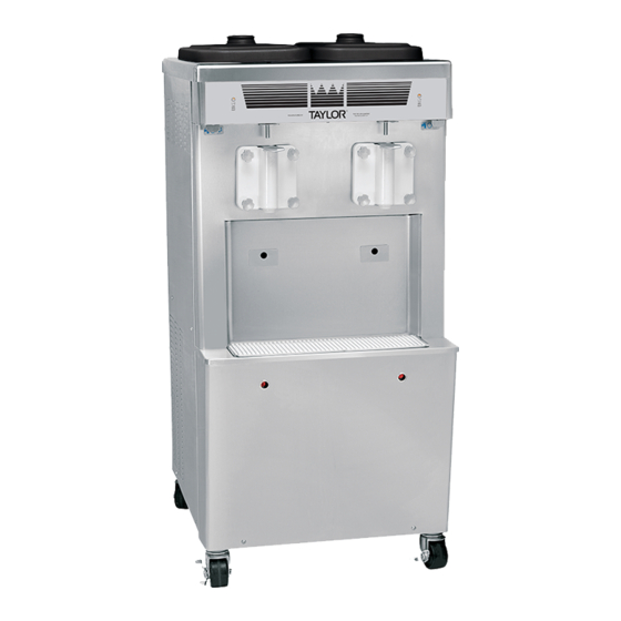
- Page 1 Models 358 & 359 Thick Shake Freezers Operating Instructions 056788-M 8/2/10...
- Page 2 Minimum Wire Ampacity: E August, 2010 Taylor All rights reserved. 056788-M Taylor Company The word Taylor and the Crown design 750 N. Blackhawk Blvd. are registered trademarks in the United States Rockton, IL 61072 of America and certain other countries.
-
Page 3: Table Of Contents
............. . Models 358 & 359... - Page 4 E July, 2010 Taylor All rights reserved. 056788-M Taylor Company The word Taylor and the Crown design 750 N. Blackhawk Blvd. are registered trademarks in the United States Rockton, IL 61072 of America and certain other countries.
-
Page 5: To The Installer
The main power supply(s) to the freezer Uncrate the unit and inspect it for damage. Report must be disconnected prior to performing any any damage to your Taylor Distributor. repairs. Failure to follow this instruction may result in personal injury or death from electrical shock or... -
Page 6: Air Cooled Units
Beater rotation must be clockwise as connections. viewed looking into the freezing cylinder. Note: The following procedures must be performed by an authorized Taylor service technician. CAUTION: THIS EQUIPMENT MUST BE PROPERLY GROUNDED! FAILURE TO DO SO To correct the rotation on a three-phase unit,... -
Page 7: Refrigerant
Refrigerant In consideration of our environment, Taylor Taylor reminds technicians to be cautious of proudly uses only earth friendly HFC refrigerants. government laws regarding refrigerant recovery, The HFC refrigerant used in this unit is R404A. This recycling, and reclaiming systems. If you have any... -
Page 8: To The Operator
Taylor Distributor, and the required service work is provided by an authorized Taylor It should also be noted that Taylor does not warrant service technician. Taylor reserves the right to deny the refrigerant used in its equipment. For example, if... -
Page 9: Safety
We, at Taylor Company, are concerned about the safety of the operator when he or she comes in contact with the freezer and its parts. Taylor has gone to extreme efforts to design and manufacture DO NOT operate the freezer unless it is built-in safety features to protect both you and the properly grounded. - Page 10 78 dB(A) when measured at a distance of surface. Failure to comply may result in personal 1.0 meter from the surface of the machine and at a injury or equipment damage. height of 1.6 meters from the floor. Safety Models 358 & 359...
-
Page 11: Operator Parts Identification
PANEL-SIDE *358* RIGHT 046023-SP1 PAN A.-DRIP X50879 FILTER A.-13 X 16-7/8 X 7/16 046044 SHIELD-SPLASH 066697 STUD-NOSE CONE 054748 TRAY-DRIP 066696 CHANNEL A.-CONTROL X63534 PANEL-SIDE *358* LEFT 046022 CASTER-SWIVEL 3/4 - 10 ST. 021279 Models 358 & 359 Operator Parts Identification... -
Page 12: Model 359
PANEL-REAR 065271 TRAY-DRIP 19-5/8 L X 4-7/8 033812 FILTER-AIR 18 L X 13.5 H X .70 052779-3 SHIELD-SPLASH-WIRE 033813 CASTER-3” SWIVEL 3/4-10STM 021279 PAN A.-DRIP X50879 PANEL-SIDE-RIGHT 065251 STUD-NOSE CONE 054748 DEFLECTOR-AIR 065200 Operator Parts Identification Models 358 & 359... -
Page 13: Beater And Door Assembly
O-RING - 1-1/16 OD x .139 W 020571 BEATER A.-7 QT. - 1 PIN X46233 DOOR-PARTIAL 1 SPOUT X30272-SER BEARING-FRONT 013116 NUT-STUD 021508 GASKET-DOOR - 5.177 ID X 016672 CLIP-SCRAPER BLADE 8.75” 046238 5.9380 BLADE-SCRAPER PLASTIC 046237 Models 358 & 359 Operator Parts Identification... -
Page 14: Accessories
Accessories Figure 4 ITEM DESCRIPTION PART NO. ITEM DESCRIPTION PART NO. KIT ASSEMBLY-TUNE UP *358 X46050 BRUSH-DRAW VALVE 014753 KIT ASSEMBLY-TUNE UP *359 X36356 BRUSH-HOPPER 3” x 7” 023316 BRUSH-REAR BEARING 013071 LUBRICANT-TAYLOR 4 OZ. 047518 BRUSH-DOUBLE ENDED 013072 SANITIZER-STERA-SHEEN... -
Page 15: Important: To The Operator
Model 358 Figure 5 Figure 6 ITEM DESCRIPTION ITEM DESCRIPTION POWER SWITCH MIX OUT INDICATOR-LEFT SIDE MIX OUT INDICATOR POWER SWITCH-LEFT SIDE RESET BUTTON MIX OUT INDICATOR-RIGHT SIDE POWER SWITCH-RIGHT SIDE RESET BUTTON Models 358 & 359 Important: To the Operator... -
Page 16: Indicator Light - "Mix Out
The reset button is located in the left side panel on the Model 358. The reset buttons are located in the lower front panel on the Model 359. The reset mechanism protects the beater motor from an overload condition. -
Page 17: Operating Procedures
Section 6 Operating Procedures The Model 358 has been selected to show you the pictured step-by-step operating procedures for both models contained in this manual. These models, for practical purposes of operation, are the same. These models store 20 quarts (18.9 liters) of mix in each hopper. - Page 18 Slide and bottom, and insert the draw valve into the the beater assembly the rest of the way into the freezer door from the top (“THIS END UP”). freezing cylinder. Figure 13 Figure 15 Operating Procedures Models 358 & 359...
- Page 19 Repeat Steps 1 through 11 for the other side of the freezer on the Model 359. Step 12 Install the front drip tray and splash shield under the door spout. Figure 17 Figure 20 Models 358 & 359 Operating Procedures...
-
Page 20: Sanitizing
Figure 24 Note: You have just sanitized the freezer. Be sure your hands are sanitized before going on Figure 22 in these instructions. Operating Procedures Models 358 & 359... -
Page 21: Priming
When full strength mix is flowing from the door spout, lower the draw handle. Note: Use only fresh mix when priming the freezer. Figure 28 Step 4 Figure 26 Fill the hopper with fresh mix. Models 358 & 359 Operating Procedures... -
Page 22: Closing Procedure
“OFF” position and lower the draw handle. Place a sanitized lid on the rerun container and place it in Repeat Steps 1 through 2 for the other side of the the walk-in cooler. freezer on the Model 359. Operating Procedures Models 358 & 359... -
Page 23: Cleaning
This will allow Repeat Steps 1 through 5 for the other side of the the o-ring to slide over the forward rings without freezer on the Model 359. falling into the open grooves. Models 358 & 359 Operating Procedures... - Page 24 Place all the cleaned parts on a clean dry surface to air dry overnight. Step 8 Figure 32 Wipe clean all exterior surfaces of the freezer. Operating Procedures Models 358 & 359...
-
Page 25: Important: Operator Checklist
Be sure there is a rear shell bearing and the female hex drive generous amount of cleaning solution on the socket clean and free of lubricant and mix brush. deposits. Models 358 & 359 Important: Operator Checklist... -
Page 26: Winter Storage
Never use screwdrivers or other metal system. probes to clean between the fins. Your local Taylor Distributor can perform this service Note: For machines equipped with an air for you. filter, it will be necessary to vacuum clean the filters on a monthly schedule. -
Page 27: Troubleshooting Guide
Warm mix was placed in b. Mix should be below 40_F (4.4_C) when placed in the hopper. hopper. c. The temperature is out of c. Contact an authorized service technician. adjustment. Models 358 & 359 Troubleshooting Guide... - Page 28 There is no mix in the mix b. Fill the mix hopper with mix. hopper. c. Circuit breaker off or c. Turn breaker on or replace fuse. blown fuse. d. Beater motor out on reset. d. Reset the freezer. Troubleshooting Guide Models 358 & 359...
- Page 29 Inadequate level of mix in a. Fill the mix hopper with mix. the freezing cylinder. the mix hopper. b. Mix inlet hole frozen up. b. Mix hopper temperature needs adjustment. Contact an authorized service technician. Models 358 & 359 Troubleshooting Guide...
-
Page 30: Parts Replacement Schedule
Double Ended Brush Inspect & Replace Minimum if Necessary White Bristle Brush, 1” x 2” Inspect & Replace Minimum if Necessary White Bristle Brush, 3” x 7” Inspect & Replace Minimum if Necessary Parts Replacement Schedule Models 358 & 359... -
Page 31: Parts List
Section 10 Parts List Models 358 & 359 Parts List... - Page 32 Parts List Models 358 & 359...
- Page 33 Models 358 & 359 Parts List...
- Page 34 Parts List Models 358 & 359...
- Page 35 Models 358 & 359 Parts List...
- Page 36 Parts List Models 358 & 359...
- Page 37 Models 358 & 359 Parts List...
- Page 38 Model 358 063532-27 Rev. 8/10...
- Page 39 Model 358 063532-33 Rev. 8/10...
- Page 40 Model 359 065467-33 Rev. 8/10...