Table of Contents
Advertisement
Quick Links
Advertisement
Table of Contents

Related Manuals for Dynacord SR20TGX-EU


Summary of Contents for Dynacord SR20TGX-EU
- Page 1 TGX Amplifier System Rack SR20TGX‑EU | SR20TGX‑US Installation manual...
-
Page 3: Table Of Contents
TGX Amplifier System Rack Table of contents | en Table of contents Safety Safety messages explained Important safety instructions Safety precautions High frequency interference – FCC/EN55032 Notices About this manual Manual purpose Digital document Intended audience System overview Application and intended use Scope of supply Front view Handling, cooling, and placement... -
Page 4: Safety
en | Safety TGX Amplifier System Rack Safety Safety messages explained Four types of signs can be used in this manual. The type is closely related to the effect that may be caused if it is not observed. These signs - from least severe effect to most severe effect - are: Notice! Containing additional information. - Page 5 TGX Amplifier System Rack Safety | en Use only a dry cloth to clean the unit. Do not cover any ventilation slots. Always refer to the manufacturer's instructions when installing the device. Do not place the device close to heaters, ovens, or other heat sources. Note: The device must only be operated via the mains power supply with a safety ground connector.
-
Page 6: Safety Precautions
en | Safety TGX Amplifier System Rack The minimum distance between voltage-carrying parts and circuit parts that are not connected to the mains (secondary) is 6 mm, and must be observed at all times. Special components that are marked with the safety symbol in the circuit diagram (note) must only be replaced with original parts. -
Page 7: Notices
For information on getting permission for reprints and excerpts, contact Dynacord. All content including specifications, data, and illustrations in this manual are subject to change without prior notice. -
Page 8: About This Manual
Digital document This manual is available as a digital document in the Adobe Portable Document Format (PDF). You can find information about Dynacord products on the product related information at www.dynacord.com. Intended audience This manual is intended for operators and users of the TGX amplifier system racks. -
Page 9: System Overview
TGX 4-Channel Power Amplifier manual Network switch quick start guide There are two versions of the system rack for use with either 230 V or 208 V 3-phase mains power. SR20TGX-EU SR20TGX-US SR10F, system rack TGX20 amplifier PD32-EU power distro... -
Page 10: Front View
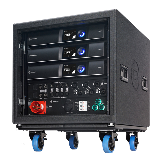
en | System overview TGX Amplifier System Rack Front view Figure 3.1: TGX system rack front view System rack, SR10F TGX20 amplifiers CP34 connector panel CP32-EU (shown) or CP30-US Dolly board with connector rails 2U blank panel (not shown on the rear) 2U tray with two network switches (not shown on the rear) 2019-03 | 02 | F.01U.346.534 Installation manual... -
Page 11: Handling, Cooling, And Placement
TGX Amplifier System Rack Handling, cooling, and placement | en Handling, cooling, and placement Handling Caution! Before transportation or use of the SRTGX rack make sure that the equipment is in good condition. Examine the rack for damage to the wheels, connector bars, connector rails, and doors. - Page 12 en | Handling, cooling, and placement TGX Amplifier System Rack Caution! A stack of three loaded racks is only safe to use straight on an even ground. A stack of three empty racks is not permitted. The center of gravity is high compared to footprint, so the stack can easily tip over and create serious damage to equipment and injuries to personnel.
-
Page 13: Cooling And Placement
TGX Amplifier System Rack Handling, cooling, and placement | en Cooling and placement When placing the TGX amplifier system racks make sure to provide a minimum space of 0.6 m (2 ft.) to the front and rear of the rack to allow sufficient airflow. In operation both doors have to be fully opened. -
Page 14: Power Distribution Panel
en | Power distribution panel TGX Amplifier System Rack Power distribution panel The TGX amplifier system racks have a power distribution panel that allows to drive the TGX amplifiers as well as the integrated network switches from one 3-phase mains connection. There are two versions available. -
Page 15: Connector Panel Cp34
TGX Amplifier System Rack Connector panel CP34 | en Connector panel CP34 The TGX system racks features the CP34 connector panel, designed for three 4-channel amplifiers with OMNEO networking. All connections for the OMENO network (incl. Dante audio and OCA), additional analogue and AES-3 inputs and the outputs to the speakers are available. - Page 16 en | Connector panel CP34 TGX Amplifier System Rack Input signals (analogue or AES3) from the CP34 connector panel are connected to the top amplifier and linked through. The audio outputs from the bottom amplifier are connected to the THROUGH sockets on the CP34. Figure 6.3: Switch tray and network wiring scheme: OMNEO (Dante audio + OCA control) The SRTGX racks feature a fully redundant network connection.
-
Page 17: System Wiring
TGX Amplifier System Rack Connector panel CP34 | en Figure 6.4: Power cabling, top to bottom phase L1, L2, L3, respect. X, Y, Z The amplifiers are connected to the power outlets of the PD32-EU / PD30-US for an optimized power input of the amplifiers. For more information, refer to the PD32/PD30 Mains Power Distributer manual. - Page 18 en | Connector panel CP34 TGX Amplifier System Rack Figure 6.6: OMNEO / Dante / OCA connection of multiple system racks with primary and secondary line If no Dante audio signal is used, or as an additional (third level) back-up, digital audio signal in AES3 format can also be connected throughout multiple racks by daisy-chaining.
-
Page 19: Using Blank Panel For Customized Connectors On The Front
TGX Amplifier System Rack Connector panel CP34 | en Using blank panel for customized connectors on the front Use the blank panel on the front for customer specific connectors (e.g. loudspeaker multicores) with SRTGX rack, it is possible to re-arrange the power distribution (PD30 / PD32) with the switch tray that is covered by a 2U 19-inch blank panel. -
Page 20: Maintenance And Inspection
Damaged or missing parts have to be replaced immediately. The overview for global service and spare parts is available on www.dynacord.com 2019-03 | 02 | F.01U.346.534 Installation manual Bosch Security Systems, Inc. -
Page 21: Technical Data
TGX Amplifier System Rack Technical data | en Technical data System rack SR20TGX Amplifier channels Audio Connections Balanced line level input / AES3 4 / 2 XLR f (Neutrik) Balanced line level out / AES3 4 / 2 XLR m (Neutrik) Amplifier outputs 3 x 2 NL8 (Neutrik speakON) Ethernet Connections... -
Page 22: Connector Panel Cp34
en | Technical data TGX Amplifier System Rack Connector panel CP34 Audio inputs 4 XLR f ( line level, 2 for AES-3) Audio outputs (through) 4 XLR m (line level, 2 for AES-3) Network connection 2 x 2 RJ45 (Neutrik etherCON) Blank for customer options Amplifier outputs 3 x 2 SpeakON NL8... -
Page 23: Cp 34 Block Diagram
TGX Amplifier System Rack Technical data | en CP 34 block diagram Bosch Security Systems, Inc. Installation manual 2019-03 | 02 | F.01U.346.534... -
Page 24: Dimensions
en | Technical data TGX Amplifier System Rack Dimensions Figure 8.1: Dimensions: SR20TGX amplifier system rack 2019-03 | 02 | F.01U.346.534 Installation manual Bosch Security Systems, Inc. - Page 28 Bosch Security Systems, Inc. 130 Perinton Parkway Fairport, NY 14450 www.dynacord.com © Bosch Security Systems, Inc., 2019...