Advertisement
Quick Links
TECHNICAL
NOTE
Solution Overview
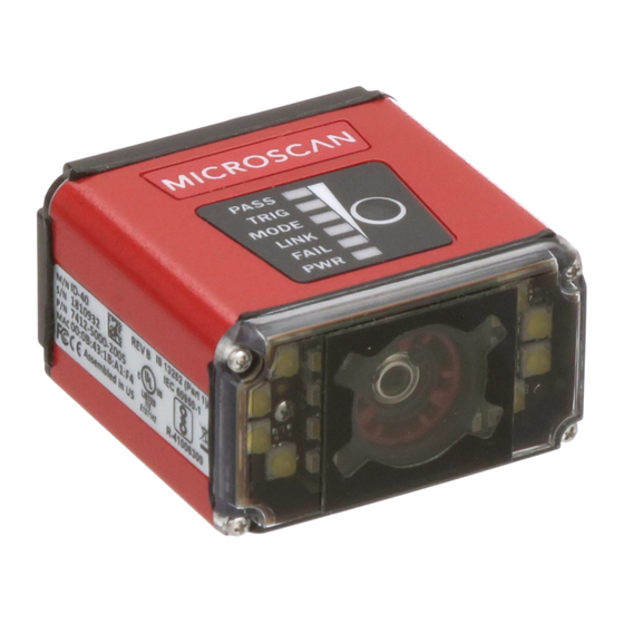
Six MicroHAWK ID-40 readers are connected in daisy chain configuration to an Omron NJ/NX machine controller
via EtherNet/IP. The NJ/NX controller sends a trigger to the readers, and once a reader decodes a symbol, the
read cycle is stopped for all readers. This solution includes a basic HMI user interface and an NA series panel.
This solution is useful in food and commodity applications in which a decode must be performed on a product's
barcode, but the barcode's location on the product's perimeter is not known. One example is the need to
decode a GS1 Data Matrix on a product as it travels down a conveyor. After the decoded data has been
delivered to the NJ/NX controller, the data could be written to a database as part of a pharmaceutical company's
serialization and traceability implementation.
Solution Features
•
Six-reader daisy chain of MicroHAWK ID-40 readers
•
Camera trigger via digital input or button on HMI
•
Three counters: Trigger, Cycles Read, Overruns
•
Counter resets via digital input or HMI
•
Decoded data displayed on HMI
•
Number ID of reader that decoded symbol displayed on HMI
•
Cycle timeout configurable on HMI
•
Read time displayed on HMI
•
Error detection: Timeout, Overrun, Communication fault on EtherNet/IP port
Supported Symbologies
•
Linear (1D) barcodes down to 10 mil:
•
Ladder (Vertical) or Picket Fence (Horizontal)
•
Picket fence width should not exceed 60% of the
diameter; see example of maximum-width picket
fence 1D barcode in the image below.
•
Minimum 1D barcode height = 0.5 inches
84-9220134-02 Rev A
MicroHAWK ID-40
360
Barcode Reading to Omron NJ/NX Controller
o
Maximum Picket
Fence Orientation
•
2D barcodes down to 15 mil
•
Data Matrix, Code 128, and UPC/EAN enabled
in the supplied WebLink configuration file.
Additional symbologies supported by modifying
the ID-40's decode setting.
•
5.1 x 3.8 inch (129.5 x 96.5 millimeter) reader FOV
when ID-40s are mounted as described.
•
Refer to MicroHAWK ID-40 Specification Sheet
for full list of supported symbologies.
Advertisement

Related Manuals for Omron MicroHAWK ID-40


Summary of Contents for Omron MicroHAWK ID-40
- Page 1 Barcode Reading to Omron NJ/NX Controller Solution Overview Six MicroHAWK ID-40 readers are connected in daisy chain configuration to an Omron NJ/NX machine controller via EtherNet/IP. The NJ/NX controller sends a trigger to the readers, and once a reader decodes a symbol, the read cycle is stopped for all readers.
- Page 2 • SYSMAC Studio, Standard Edition, version 1.23. • Internet browser to connect the MicroHAWK ID-40 to WebLink. Hardware This solution can be implemented on NJ or NX machine controllers. Two example hardware equipment lists are provided. Configuration 1 uses an NJ301 and Configuration 2 uses an NX1P2.
-
Page 3: Configuration Files
Configuration 2 – NX1P2 Controller Quantity Part Number Description Version 7412-2000-2005 MicroHAWK ID-40, SXGA, HD, Autofocus, WHT, HS, X 1.3.0.3009 97-000012-01 Power Supply, 100-240 VAC, +24 VDC, M12 12-Pin Socket 61-000163-03 QX Cordset, Host, Ethernet, M12 8-Pin Plug (Screw-On)-to-RJ45, 3 m... - Page 4 TECHNICAL Technical Note: MicroHAWK ID-40 360 Barcode Reading Solution º NOTE MicroHAWK ID-40 Setup MicroHAWK ID-40 Hardware Mounting MicroHAWK ID-40 Hardware Mounting Install ID-40 readers as shown in the file “ID-40 360 read cam placement.dwg”. The basic layout is shown below.
- Page 5 MicroHAWK ID-40 Configuration MicroHAWK ID-40 Configuration Connect the power and Ethernet cables to ONLY ID-40 reader 1. 2.2. Using an internet browser type the IP address of the camera. (The factory default IP address is 192.168.188.2. If necessary, change the PC's IP address to 192.168.188.101, subnet 255.255.0.0, to be on the same subnet.) This will allow you to use WebLink to configure the ID-40.
- Page 6 2.3.5.1. Image Processing Timeout = 150 ms • This setting sets a limit on how long the MicroHAWK ID-40 will attempt to read the barcode in the current image. You will need to determine the decode time for a good read (circled in the image below) and then set this value to slightly higher.
- Page 7 2.6.1. Click the gear icon > Advanced > Communications as shown below. 2.6.2. Set the IP addresses and subnets to the values listed below: • Reader 1 = 192.168.250.11, subnet 255.255.255.0 • Reader 2 = 192.168.250.12, subnet 255.255.255.0 • Reader 3 = 192.168.250.13, subnet 255.255.255.0 •...
- Page 8 º NOTE MicroHAWK ID-40 EDS File Download 3. ID-40 EDS File 3.1. Download the MicroHAWK Barcode Reader EDS file from the Omron Microscan download center, as shown below. (https://files.microscan.com/downloadcenter/MicroHAWK%20Auto%20 ID%201.2%20EtherNetIP.zip.) 3.2. Extract the file “MicroHAWK Auto ID 1.2 EtherNetIP.zip” to your hard drive at “C:\MicroHAWK Auto ID 1.2...
- Page 9 4.6. Mount the sensor emitter and receiver units on opposite sides of the conveyor at the location indicated in section 1 of this document, titled "MicroHAWK ID-40 Hardware Mounting". The emitter and receiver units must point at each other. 4.7.
- Page 10 TECHNICAL Technical Note: MicroHAWK ID-40 360 Barcode Reading Solution º NOTE 4.10. Apply power to the power supplies powering the NJ/NX controller and NA HMI Panel. 4.11. Wait approximately 30 seconds for these components to fully power up. 4.12. At this point all components should be powered and connected to the Ethernet switch. Confirm that network activity is seen from the NJ/NX controller, the NA HMI Panel, and the six ID-40 readers.
- Page 11 Establish NJ/NX Communications with PC The default IP address for NJ/NX port 1 (EtherNet/IP) is 192.168.250.1, subnet 255.255.255.0. On some Omron controllers, such as the NX1P2 (configuration 2), these units can only communicate via a built-in EtherNet/IP port.
- Page 12 This type of connection can be used for modifications to NJ/NX settings (such as the IP Address) or changes to logic, but for full configuration and testing of EtherNet/IP, use the Ethernet connection described in step 7 of the section "Omron NJ/NX Controller Ethernet Connection via a Hub". 6. NJ Direct USB Connection 6.1.
- Page 13 Omron NJ/NX Controller Ethernet Connection via a Hub 7. Omron NJ/NX Controller Ethernet Connection via a Hub 7.1. Click Controller menu > Communications Setup as shown on page 14. 7.2. Click the "Ethernet Connection via a Hub" button as shown below.
- Page 14 TECHNICAL Technical Note: MicroHAWK ID-40 360 Barcode Reading Solution º NOTE Modify NJ/NX Controller IP Address 8. Modify NJ/NX Controller IP Address 8.1. In the Multiview Explorer, expand “Configurations and Setup”, expand the “Controller Setup”, and double-click “Built-in EtherNet/IP Port Settings”. The IP address will be shown for the current project, as shown below.
- Page 15 9.2. Two data types are created in this application. The data type for the Input Assembly 103 is called “s_ID40_ Input_type_103” and is shown below. 9.3. The data type for the Output Assembly 197 is called “s_ID40_Output_type_197” and is shown below. Note that when creating these data types, the Offset Type must be changed to “User”.
- Page 16 Download Project to Controller Before starting this process, SYSMAC Studio should be configured to communicate using Ethernet connection via hub. If this has not been completed, follow steps starting at 7.1, found in the section "Omron NJ/NX Controller Ethernet Connection via a Hub".
- Page 17 11.2. SYSMAC Studio may display a warning message if the NJ/NX does not have a name. If you see the warning shown below, click "Yes". 11.3. Once online, a yellow line will be drawn under the toolbar. Click the "Synchronize" button, which is identified below.
- Page 18 After changing the IP address of the NJ/NX controller, SYSMAC Studio may not be able to communicate with the controller and you may need to wait for SYSMAC Studio to respond. Go to the section "Omron NJ/NX Controller Ethernet Connection via a Hub" to re-establish the network connection with the controller.
- Page 19 You should see that a new item has been added to the EDS Library window called Microscan Systems, Inc., as indicated by the arrow in the image below. This indicates that the MicroHAWK ID-40 EDS file has been added to SYSMAC Studio. Click "Close".
- Page 20 Enter the IP address for the first ID-40, which in this example is 192.168.250.11. Click the "Model name" dropdown menu and select MicroHAWK ID-40. In the Revision dropdown select 1. When completed it should resemble the image below. Click the + button, which is found at the bottom of the Toolbox dialog.
- Page 21 13.3. A new target device should be displayed in the Toolbox with the IP address of the reader that was just entered. 13.4. Repeat steps 13.1 through 13.3 for the remaining ID-40 readers. Their IP addresses are listed below. • 192.168.250.12 •...
- Page 22 TECHNICAL Technical Note: MicroHAWK ID-40 360 Barcode Reading Solution º NOTE 13.7. In the Tag Set Registration Setting window, confirm all ID-40 input and output tags are checked and click "Register", as shown below. Click the "Connection" button, which is circled below. Click the + button to add the first EtherNet/IP 13.8.
- Page 23 13.10. Click the "Input Target Variable" (first line), which defines the input assembly used in the EDS file, and type 103. This field is circled in red below. Select the Originator Variable, circled in yellow, and select ID40_Input01 in the dropdown field. In the RPI field, circled in green, change this value to 20.0. Note that the RPI for the ID-40 cannot be set to an amount less than 10 ms.
- Page 24 TECHNICAL Technical Note: MicroHAWK ID-40 360 Barcode Reading Solution º NOTE Transfer EtherNet/IP Configuration to NJ/NX Controller Check EtherNet/IP Communications 14.1. Ensure that SYSMAC Studio is online with the controller by verifying that there is an orange line under the toolbar. If necessary, click the "Online" button, which is identified by a red circle in the image below.
- Page 25 Check EtherNet/IP Communications in SYSMAC Studio Check EtherNet/IP Communications in SYSMAC Studio 15.1. Click the "EtherNet/IP Device List" tab. If this tab is not present, go to the Tools menu and select "EtherNet/IP Connection Settings". Right-click the controller IP address and select "Monitor" as shown below. 15.2.
- Page 26 TECHNICAL Technical Note: MicroHAWK ID-40 360 Barcode Reading Solution º NOTE 15.4. Once the issue has been corrected, it may take up to a minute for the Connection Status to update in SYSMAC Studio. 15.5. Once all the connections are established as shown below, the project should be saved by going to the File menu and selecting Save As and typing the project name.
- Page 27 In the Specify IP Address field, enter the IP address for the NA-HMI panel. The default address for an NA-HMI panel, port 1, is: 192.168.250.2. 16.7. Click "Test". 16.8. Be sure “Test OK” shows in the white bar as shown below. This will indicate you have good communications with the Omron controller. 16.9. Click "OK" when ready.
- Page 28 TECHNICAL Technical Note: MicroHAWK ID-40 360 Barcode Reading Solution º NOTE Modify NA-HMI Panel IP Address NA-HMI Panel Download 17.1. In the Multiview Explorer, expand “Configuration and Setup” and double-click “HMI Settings”. Click the “TCP/IP” button, circled below, to view the IP Address for Ethernet Port 1 on the NA-HMI panel.
- Page 29 Download the Project to the NA-HMI Panel Download the Project to the NA-HMI Panel 18.1. Click the "Online" button, which is identified in the image below. • If this is the first time that you have used the NA-HMI panel, the firmware may need to be updated.
- Page 30 TECHNICAL Technical Note: MicroHAWK ID-40 360 Barcode Reading Solution º NOTE 18.4. The example below shows the synchronization page once it is completed. Click "Close". HMI User Interface At this point the user interface, shown below, is now visible on the NA-HMI panel.
- Page 31 Finishing Solution Installation Optimizing the Trigger Position For the fastest read times, the trigger position should be adjusted so that the barcode is read on either the first or second image capture regardless of barcode orientation. Optimizing the Trigger Position 19.1.
- Page 32 TECHNICAL Technical Note: MicroHAWK ID-40 360 Barcode Reading Solution º NOTE 20.2. In the WebLink display area, click the button circled in the image above so that it is highlighted blue. This enables Show All Images Used in Read Cycle. The image in the upper left will be the first image captured and the last image will be the rightmost image on the bottom row.
- Page 33 Set Read Timeout The Read Timeout is the maximum time allowed for the decode. The NJ/NX controller project has the Read Timeout set to 2,000 milliseconds by default. This default value is defined by the value entered in the Initial Value field for the HMI_ReadTimeout variable.
- Page 34 TECHNICAL Technical Note: MicroHAWK ID-40 360 Barcode Reading Solution º NOTE Change the Default Read Timeout Change the Default Read Timeout 22.1. Open the Global Variable page in SYSMAC Studio. See step 10.1 in the section Global Variables. 22.2. Set the initial value field of the variable ReadTime to the desired timeout in milliseconds.
- Page 35 Appendix A Known Issues Known Issues 23.1. The Min_OnTime (TOF) timer is used to extend short duration trigger signals to ensure that the ID-40 readers can have their EtherNet/IP triggers forced low (to stop the previous read if still reading), receive the acknowledgement that the units are no longer triggered, and then trigger the readers for the new cycle.
- Page 36 TECHNICAL Technical Note: MicroHAWK ID-40 360 Barcode Reading Solution º NOTE Appendix B Important Global Variables Global Variable Data Type Used For Notes ID40_Input01 S_ID40_Input_type_103 EtherNet/IP ID-40 Reader 1 ID40_Input02 S_ID40_Input_type_103 EtherNet/IP ID-40 Reader 2 ID40_Input03 S_ID40_Input_type_103 EtherNet/IP ID-40 Reader 3...
- Page 37 Appendix C Useful Documentation / Files SYSMAC Studio Operation Manual: https://industrial.omron.us/en/media/Sysmac_Studio_Ver1_18_ OperationManual_en_201704_W504-E1-20_tcm849-112701.pdf NJ/NX CPU Unit Built-In EtherNet/IP Port: https://industrial.omron.us/en/media/NJNX-series_CPU_Unit_Built- in_EtherNetIP_Manual_EN_201811_W506I-E3-20_tcm849-112708.pdf NX1P2 CPU Unit Hardware User Manual: https://industrial.omron.us/en/media/NX1P2_Hardware_UsersManual_ en_201611_W578-E1-01_r2_tcm849-112522.pdf NX1P2 Built-In I/O User Manual: https://industrial.omron.us/en/media/NX1P2_IO_Option_Boards_UsersMan_ en_201611_W579-E1-01_r22_tcm849-112521.pdf NX-ECC202 User Manual: https://industrial.omron.us/en/media/NX-ECC_EtherCAT_Coupler_UsersManual_ en_201504_W519-E1-05_tcm849-113365.pdf NX-Series Digital I/O: https://www.fa.omron.com.cn/data_pdf/cat/nx-id_ia_od_oc_md_ds_e_3_2_csm1057421.
- Page 38 OMRON AUTOMATION AMERICAS HEADQUARTERS • Chicago, IL USA • 847.843.7900 • 800.556.6766 • www.omron247.com OMRON CANADA, INC. • HEAD OFFICE OMRON ELETRÔNICA DO BRASIL LTDA • HEAD OFFICE Toronto, ON, Canada • 416.286.6465 • 866.986.6766 • www.omron247.com São Paulo, SP, Brasil • 55.11.2101.6300 • www.omron.com.br OMRON ELECTRONICS DE MEXICO •...