Table of Contents
Advertisement
Quick Links
Advertisement
Chapters
Table of Contents

Related Manuals for Omron V400-R2 Series


Summary of Contents for Omron V400-R2 Series
- Page 1 V400-R2 Series User’s Manual Z333-E1-01A Cat. No.
- Page 2 Introduction Thank you for purchasing the OMRON V400-R2 series. This manual describes the functions, performance, and application methods of the V400-R2 series. This manual is intended for personnel with knowledge of electrical systems. Be sure to read and understand this manual thoroughly before using the product, and keep this manual in an easily accessible location for quick reference when required.
-
Page 3: Section
Introduction Introduction READ AND UNDERSTAND THIS DOCUMENT (Be sure to read this.) Section Product Overview Section Introduction Procedure Section Basic Knowledge of Operation Section Setting Method Section Appendix Multi-code Reader User’s Manual V400-R2 series... - Page 4 PRODUCTS, WHETHER SUCH CLAIM IS BASED ON CONTRACT, WARRANTY, NEGLIGENCE, OR STRICT LIABILITY. In no event shall responsibility of OMRON for any act exceed the individual price of the product on which liability is asserted. IN NO EVENT SHALL OMRON BE RESPONSIBLE FOR WARRANTY, REPAIR, OR OTHER CLAIMS REGARDING THE PRODUCTS UNLESS OMRON’S ANALYSIS CONFIRMS THAT THE PRODUCTS...
- Page 5 Performance data given in this document is provided as a guide for the user in determining suitability and does not constitute a warranty. It may represent the result of OMRON’s test conditions, and the users must correlate it to actual application requirements. Actual performance is subject to the OMRON Warranty and Limitations of Liability.
-
Page 6: Safety Precautions
In this operation manual, precautions are indicated using the following symbols and signal words to ensure safe use of the V400-R2 series. The precautions indicated by these symbols and signal words are important to ensure safety and must be observed. -
Page 7: Introduction
Introduction Regulations and Standards This product complies with the following standards. LED safety standard IEC 62471-1:2006 Risk exempt group EN standard (CE mark) EN55022/EN55024 V400-R2 series User’s Manual... -
Page 8: Precautions For Safe Use
2. Power Supply and Wiring • To assure noise and insulation resistance, be sure to use S8VS-01505 (made by OMRON) as a driving power supply. • Do not connect a voltage or AC power supply that has a voltage exceeding the rating voltage (5 V+/-10%). - Page 9 • Dispose of the product as industrial waste. • If the product becomes extremely hot, or abnormal odors or smoke are emitted, stop using the product immediately, turn the power OFF, and consult with your OMRON representative. V400-R2 series...
-
Page 10: Precautions For Correct Use
• droplets, water mist, oil or chemical agents. 2. Power supply, connection, and wiring • Be sure to use S8VS-01505 (made by OMRON) as a driving power supply. • Do not install the product in a location where a high-voltage device is installed. - Page 11 Do not blow using your own breath. • Gently wipe off small particles using a soft cloth (lens wiper) moistened with a small amount of alcohol. Avoid vigorous wiping. Scratches on the reading window may result in reading errors. V400-R2 series User’s Manual...
-
Page 12: How To Use This Manual
Bar code (Paper which a bar code is printed on) Narrow bar (Slim lines) Margin Margin Height Width 2D code Label 2D code (Paper on which a 2D code is printed on) Cell size Matrix size Margin V400-R2 series User’s Manual... - Page 13 Correct Header Footer reading data Footer V400-R2 series User’s Manual Operation procedure and additional explanation Shows the operation procedure. Tips and reference pages that may be useful during operation are indicated with a mark. * This page does not actually exist.
-
Page 14: Visual Aids
• QR Code is a registered trademark of DENSO WAVE INCORPORATED in JAPAN and other countries. • Other system names and product names that appear in this manual are the trademarks or registered trademarks of the respective companies. V400-R2 series User’s Manual... -
Page 15: Table Of Contents
Product Overview Features Basic Configuration Part Names and Functions Section 2 Introduction Procedure Introduction Flow Chart Preliminary Examination Wiring and Connection Preparation Installation and Reading Section 3 Basic Knowledge of Operation Operation Flow Chart Communication Data Format V400-R2 series User’s Manual... - Page 16 Introduction Section 4 Setting Method How to Use a Menu Sheet/Command Menu Sheet/Command List Section 5 Appendix Maintenance Troubleshooting Specifications and External Dimension ASCII Code Table Quick-Reference Tables of Data Capacities V400-R2 series User’s Manual...
-
Page 17: Product Overview
Section 1 Product Overview This section explains the features, ratings, and performance of this product. Features Basic Configuration Part Names and Functions V400-R2 series User’s Manual... -
Page 18: Features
Readable barcodes and 2-dimensional barcodes are shown below. Model bar codes 2D codes V400-R2CF65 0.076 mm 0.169 mm V400-R2CF125 0.127 mm 0.212 mm Green LED aiming function The green LED aiming function quickly recognizes the area to be read. V400-R2 series User’s Manual... - Page 19 The main body is very small, only 41.1 mm × 33 mm × 24 mm. The front and side view types are available to suit your installation environment. 33 mm 41.1 mm 24 mm V400-R2 series V400-R2 series User’s Manual...
-
Page 20: Basic Configuration
The cable has a connector at the end. Use the appropriate connecting cable for the upper equipment. PC/AT compatible Multi-code reader Cable for connecting PC/AT compatible V400-R2 series V509-W011D p.33 Power supply (5 VDC) Dedicated product: S8VS-01505 (made by OMRON) Programmable controller p.34 Programmable controller made by OMRON Connecting cable V509-W011 V400-R2 series User’s Manual... -
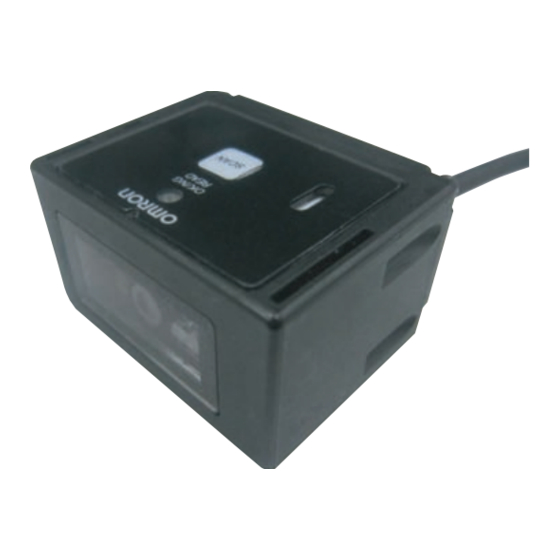
Page 21: Part Names And Functions
SCAN button reading once. Read confirmation LED LED (green) illuminates when reading is successful. Connected to a cable for connecting PC/AT compatible or a Main cable programmable controller made by OMRON. The length is 1.5 m. V400-R2 series User’s Manual... - Page 22 Section 1 Product Overview MEMO V400-R2 series User’s Manual...
-
Page 23: Introduction Procedure
Section 2 Introduction Procedure A flow chart of pre liminary examination, installation, and introduction of th e product is as shown below. Introduction Flow Chart Preliminary Examination Wiring and Connection Preparation Installation and Reading V400-R2 series User’s Manual... -
Page 24: Introduction Flow Chart
Testing Investigate the reading timing. Preparation p.38 Investigation into the reading timing p.46 Basic operation flow chart Set the reading condition corresponding to the purpose. p.39 Setting the reading conditions p.58 Menu Sheet/Command List V400-R2 series User’s Manual... - Page 25 Test in the actual usage environment. Installation and reading p.37 Testing Execute reading. In case of trouble: I do not know the I cannot understand the communication specification. operation flow. p.46 Operation Flow Chart p.52 Communication Data Format V400-R2 series User’s Manual...
-
Page 26: Preliminary Examination
11 × 11 to 17 × 17 21 × 21 to 57 × 57 10 × 10 to 64 × 64 (Versions 1 to 10) 8 × 18 to 16 × 48 PDF417 Micro PDF417 Aztec Code Maxi Code Codablock-F V400-R2 series User’s Manual... - Page 27 Section 2 Introduction Procedure Bar codes JAN/EAN and UPC CODE39 Industrial2of5(STF) Codabar(NW-7) CODE93 CODE128 V400-R2 series User’s Manual...
- Page 28 Section 2 Introduction Procedure GS1 DataBar (RSS) GS1 DataBar Omni-directional GS1 DataBar Truncated GS1 DataBar Stacked GS1 DataBar Limited GS1 DataBar Expanded GS1 DataBar Composite V400-R2 series User’s Manual...
- Page 29 Tilt angle γ = 0°, curvature R = ∞ •Reading rate: 90% or more in 10 tries The reading range is a reference value, not a guaranteed value. (Unit: mm) (48, (93, (Horizontal field of view, Vertical field of view) V400-R2 series User’s Manual...
- Page 30 41 × 26 to 63 × 40 0.254 50 to 115 37 × 23 to 85 × 54 Code128 0.18 45 to 100 33 × 21 to 74 × 47 0.33 45 to 120 33 × 21 to 89 × 56 V400-R2 series User’s Manual...
-
Page 31: Pitch Angle
LED light or room illumination light enters the reading window. If reflected illumination LED light is the culprit, reading performance can be improved by providing an angle of about 15° in the skew direction. V400-R2 series User’s Manual... -
Page 32: Tilt Angle
12-digit UPC, resolution = 0.33 mm, PCS = 0.9 • Reading distance: 65 mm (V400-R2CF65) or 105 mm (V400-R2CF65) from the case end • Installation condition: Pitch angle α = 0°, skew angle β = 15°, tilt angle γ = 0° V400-R2 series User’s Manual... -
Page 33: Wiring And Connection
For cable relay Hosiden Corporation TCS8587-0170477 For panel installation Hosiden Corporation TCS1080-0120177 The OK and NG output lines are not connected to the DIN 8-pin connector. To use the OK and NG outputs, cut the cables. Input/output circuit V400-R2 series User’s Manual... - Page 34 READ OK/NG signal output circuit OK/NG Internal circuit Item Specification Output system NPN open collector Rated load 24 VDC 30 mA Leak current at OFF 0.5 mA or less Residual voltage at ON 1 V or less V400-R2 series User’s Manual...
-
Page 35: Example Of Connection With A Pc
Example of connection with PC/AT compatible is explained. Multi-code reader V400-R2 series PC/AT compatible Special cable V509-W011D 100 VAC Dedicated power supply for multi-code reader S8VS-01505 (made by OMRON) Wiring Upper equipment side Reader side (Example with PC/AT compatible) Pin No. Wire color Signal name Pin No. - Page 36 Section 2 Introduction Procedure Example of connection with programmable controller (CS1) Connection with programmable controller CS1 (made by OMRON) is explained. Power supply unit CPU unit Input unit Reader C200HW-PA204S CS1H-CPU67H Programming console CS1W-ID21 V400-R2 series C200H-PRO27 Trigger switch Special cable...
- Page 37 Transmits “NL” when no label is found TH0N0L Transmits “ND” when reading has failed TI0N0D Settings on OMRON programmable controller CS1 For information about the detailed setting method, refer to the operation manual of your programmable controller. Setting item Setting content...
- Page 38 Check that the product has started up, and then start communication with upper equipment. Indefinite signals may be generated from the upper interface while the product starts up. Clear the receive buffer of the devices before starting initial operation. V400-R2 series User’s Manual...
-
Page 39: Preparation
In reading rate measurement mode, the reading rate in every 10 reading operations is output continuously to the upper equipment. The number of times of successful decoding (no verification) 10 reading tries 10/10 Correct reading data ABCDEFG Communication data format Header Footer Correct Footer Header reading data Footer V400-R2 series User’s Manual... - Page 40 When the trigger input method is external trigger signal effective duration designation system or RS-232C command, effective duration setting is required beforehand. The effective duration is set between 0 and 10 seconds. Effective duration setting method p.72 V400-R2 series User’s Manual...
- Page 41 Read the menu sheet for the setting item you want to change. Menu Sheet/Command List p.58 To finish, read the menu sheet “ZZ” that starts/ends the setting procedure. The buzzer stops and the reader returns to the normal mode. _ZZ_ V400-R2 series User’s Manual...
- Page 42 You can create a menu sheet using readily available code creation software, as shown below. E.g.: When creating a menu sheet “A3” Create “* A3 *” and cut the parts of “*” with scissors to create the menu sheet “A3”. *_A3_* Cutting off section Cutting off section V400-R2 series User’s Manual...
- Page 43 Section 2 Introduction Procedure Inputting a command from the upper equipment Multi-code reader Upper equipment V400-R2 series Transmits command character strings Transmit the command character strings of the function you want to set. Command Menu Sheet/Command List p.58 Transmit the command “Z2” to write the setting data in the nonvolatile memory of the reader.
-
Page 44: Installation And Reading
The mounting bracket supplied with the reader can be tilted between -30 and +30 Use this mounting bracket. Attach the mounting bracket to the reader (M2 × 6 screws, Tightening torque: 0.15 N·m). M2×6 screw M2×6 screw Mounting bracket V400-R2 series User’s Manual... - Page 45 M5 × 10 screw • Do not apply stress to the cable when installing or using. • The reading distance and angle ranges may differ depending on labels. Before installing the reader, check that the label is read successfully. V400-R2 series User’s Manual...
- Page 46 Section 2 Introduction Procedure MEMO V400-R2 series User’s Manual...
-
Page 47: Basic Knowledge Of Operation
Section 3 Basic Knowledge of Operation This section explains main functions of the reader. Operation Flow Chart Communication Data Format V400-R2 series User’s Manual... -
Page 48: Operation Flow Chart
*1: When the trigger by a command is used, ignore this clause. *2: When the trigger controlled system is used (codes are read while the trigger is ON), the reading effective duration is set to 0. V400-R2 series User’s Manual... - Page 49 *1: When the trigger by a command is used, ignore this clause. *2: When the trigger controlled system is used (codes are read while the trigger is ON), the reading effective duration is set to 0. V400-R2 series User’s Manual...
- Page 50 *1: When the trigger by a command is used, ignore this clause. *2: When the trigger controlled system is used (codes are read while the trigger is ON), the reading effective duration is set to 0. V400-R2 series User’s Manual...
- Page 51 Nonprocedural system (no protocol system) The reader transmits the data to the upper equipment and ends the communication. Multi-code reader V400-R2 series Data Upper equipment ACK/NAK system The reader waits for a response from the upper equipment after transmitting the data.
- Page 52 (Data length) + (In case when parity exists) + (Number of stop bits) x (Number of digits of Communication = (Communication speed) communication data + Number of time (ms) header characters + Number of footer characters) x 10 V400-R2 series User’s Manual...
- Page 53 (Data length) + (In case when parity exists) + (Number of stop bits) x (Number of digits of Communication= (Communication speed) communication data + Number of time (ms) header characters + Number of footer characters) x 10 V400-R2 series User’s Manual...
-
Page 54: Communication Data Format
Communication Data Format This section explains the format of communication between the reader and upper equipment. Multi-code reader Upper equipment V400-R2 series Input command Reading data output Inputting a reading trigger using an RS-232C command The reading trigger command format is as shown below. - Page 55 Error message - No label This message is returned when no code exists Not transmitted in the field of view. Error message - Decoding failure This message is returned when the code Not transmitted cannot be read. Setting method p.75 V400-R2 series User’s Manual...
- Page 56 Check that the product has started up, and then start communication with upper equipment. Indefinite signals may be generated from the upper interface while the product starts up. Clear the receive buffer of the devices before starting initial operation. V400-R2 series User’s Manual...
-
Page 57: Setting Method
Section 4 Setting Method This section explains setting methods using a menu sheet and by entering a command from the upper equipment. How to Use a Menu Sheet/Command Menu Sheet/Command List V400-R2 series User’s Manual... -
Page 58: How To Use A Menu Sheet/Command
Read the menu sheet for the setting item you want to change. Menu Sheet/Command List p.58 To finish, read the menu sheet “ZZ” that starts/ends the setting procedure. The buzzer stops and the reader returns to the normal mode. _ZZ_ V400-R2 series User’s Manual... - Page 59 Create “* A3 *” and cut the parts of “*” with scissors to create the menu sheet “A3”. *_A3_* Cutting off section Cutting off section Inputting a command from the upper equipment Refer to “Inputting a command from the upper equipment” (p.41). V400-R2 series User’s Manual...
-
Page 60: Menu Sheet/Command List
Setting for READ OK signal output p.79 Setting for label registration p.81 Setting for communication conditions p.82 Setting for the communication protocol p.84 Setting for the header and footer p.85 Number of digit output p.86 Direct code designation p.87 V400-R2 series User’s Manual... -
Page 61: Start/End Setting Using Menu Sheets
Setting for external trigger signal Select positive logic or negative logic of the external trigger signal. Menu sheet Command External trigger signal, positive logic (H active) _YA_ External trigger signal, negative logic (L active) (factory default setting) _YB_ V400-R2 series User’s Manual... -
Page 62: Return To The Factory Default Setting
Not specified digits Reading valid time 2 seconds Plural reading reset 6 frames time READ OK LED illumination time: 200 ms Buzzer Enable the buzzer Single-tone buzzer Buzzer sound duration: 50 ms Buzzer sound volume: Max V400-R2 series User’s Manual... - Page 63 Communication speed 9600 bps conditions Data length 8 bits Parity None Stop bit 1 bit Header None Footer Number of digit output None RS/CS control None (no protocol system) CS waiting time Not limited ACK/NCK waiting time Not limited V400-R2 series User’s Manual...
-
Page 64: Setting Of Reading Permission And Prohibition
Reading permission for UPC codes _R1_ Permission for UPC add-on 2-digit codes _R2_ Permission for UPC add-on 5-digit codes _R3_ Reading permission for JAN/EAN codes _R4_ Permission for EAN add-on 2-digit codes _R5_ Permission for EAN add-on 5-digit codes _R6_ V400-R2 series User’s Manual... - Page 65 Reading permission for GS1 DataBar (RSS-14) codes _JX_ Reading permission for GS1 DataBar (RSS-Limited) codes _JY_ Reading permission for GS1 DataBar (RSS-Expanded) codes _DR_ Reading permission for GS1 DataBar Composite [BHE _BHE_ Reading permission only for DataMatrix (ECC200) codes [BCC _BCC_ V400-R2 series User’s Manual...
- Page 66 Reading permission for Micro QR codes [D2U _D2U_ Reading permission for PDF417 codes [BCF _BCF_ Reading permission for MicroPDF417 [BCG _BCG_ Reading permission for AztecCode [BCH _BCH_ Reading permission for MaxiCode [BCE _BCE_ Reading permission for Codablock-F [D4P _D4P_ V400-R2 series User’s Manual...
-
Page 67: Detail Setting For Reading Code
Transfer C/D without an 0 in the beginning (Factory default setting) _E7_ Not transfer C/D without an 0 in the beginning _E9_ Transfer C/D with 0 in the beginning _E6_ Not transfer C/D with 0 in the beginning _E8_ V400-R2 series User’s Manual... - Page 68 Transfer C/D (Factory default setting) _6I_ Not transfer C/D _6H_ CODE39 Menu sheet Command Not calculate C/D (Factory default setting) _C1_ Calculate C/D _C0_ Transfer C/D (Factory default setting) _D9_ Not transfer C/D _D8_ Transfer ST/SP _D0_ V400-R2 series User’s Manual...
- Page 69 Not calculate C/D (Factory default setting) _H7_ Calculate C/D _H6_ Transfer C/D (Factory default setting) _H8_ Not transfer C/D _H9_ Not transfer ST/SP (Factory default setting) _F0_ ST/SP: ABCD/ABCD _F3_ ST/SP: abcd/abcd _F4_ ST/SP: ABCD/TN*E _F1_ ST/SP: abcd/tn*e _F2_ V400-R2 series User’s Manual...
- Page 70 Not calculate C/D (Factory default setting) _G0_ Calculate C/D _G1_ Transfer C/D (Factory default setting) _E0_ Not transfer C/D _E1_ Data character of at least 1 digit _GE_ Data character of at least 3 digits _GF_ V400-R2 series User’s Manual...
- Page 71 Data character of at least 5 digits _GI_ GS1-128(EAN-128) Menu sheet Command Disable GS1 conversion (Factory default setting) [X/0 _X/0_ Enable GS1 conversion [X/4 _X/4_ GS1-Databar(RSS) Menu sheet Menu sheet Command Not transfer C/D _DM_ Transfer C/D _DL_ V400-R2 series User’s Manual...
-
Page 72: Setting Of Inverted Code
Inverted codes can be read when the “Inverted code” option is selected. Menu sheet Command Normal (regular) code (Factory default setting) _V2_ _V2_ Normal (regular) and inverted codes _V4_ _V4_ Inverted codes _V3_ V400-R2 series User’s Manual... -
Page 73: Setting For The Number Of Times Of Reading Coincidence
Reading twice and verification once (Factory default setting) _X1_ Reading three times and verification twice _X2_ Reading four times and verification three times _X3_ Reading five times and verification four times _BS_ Reading six times and verification five times _BT_ V400-R2 series User’s Manual... -
Page 74: Setting For Reading Operation
0 sec., reading is controlled by the external trigger and the trigger is effective while the external trigger is ON. Menu sheet Command 0 seconds (controlled by the external trigger) _Y0_ 1 second _Y1_ 2 seconds (Factory default setting) _Y2_ 3 seconds _Y3_ V400-R2 series User’s Manual... - Page 75 Section 4 Setting Method Menu sheet Command 4 seconds _Y4_ 5 seconds _Y5_ 6 seconds _Y6_ 7 seconds _Y7_ 8 seconds _Y8_ 9 seconds _Y9_ Infinity _YM_ V400-R2 series User’s Manual...
-
Page 76: Setting For Plural Reading Reset Time
(Example) Frame Time (ms) 100 200 300 400 500 Menu sheet Command 1 frame _AH_ 2 frames _AI_ 3 frames _AJ_ 4 frames _AK_ 5 frames _AL_ 6 frames (Factory default setting) _AM_ Infinity _AG_ V400-R2 series User’s Manual... -
Page 77: Setting For Failed Reading
Error - No label (TH) Error - Decoding failure (TI) N (0N) N (0N) L (0L) D (0D) <CR> (1M) <CR> (1M) Setting end (ZZ/Z2) Setting end (ZZ/Z2) Menu sheet Command Error message - No label _TH_ V400-R2 series User’s Manual... -
Page 78: Setting For The Number Of Reading Digits
Read the second code of the necessary length Setting end (ZZ) Menu sheet Command Fixed number of digits OFF for all codes (Factory default setting) _H0_ Fixed number of digits ON for all codes None _H1_ V400-R2 series User’s Manual... -
Page 79: Setting For The Read Ok Led
The buzzer is enabled or disabled or its type and sound duration and volume are set. The buzzer sounds when reading succeeds. Menu sheet Command Disable the buzzer _W0_ Enable the buzzer (Factory default setting) _W8_ Single-tone buzzer (Factory default setting) _W1_ V400-R2 series User’s Manual... - Page 80 _W4_ Buzzer sound duration: 200 ms _W5_ Buzzer sound duration: 400 ms _W6_ Buzzer sound volume: Max (Factory default setting) _T0_ Buzzer sound volume: High _T1_ Buzzer sound volume: Medium _T2_ Buzzer sound volume: Low _T3_ V400-R2 series User’s Manual...
-
Page 81: Setting For Read Ok Signal Output
[X*D _X*D_ One-shot system (positive logic, H active) [X*E _X*E_ One-shot system (negative logic, L active) [X*F _X*F_ One-shot duration: 10 ms [X*G _X*G_ One-shot duration: 20 ms [X*H _X*H_ One-shot duration: 30 ms [X*I _X*I_ V400-R2 series User’s Manual... - Page 82 One-shot duration: 50 ms [X*K _X*K_ One-shot duration: 60 ms [X*L _X*L_ One-shot duration: 70 ms [X*M _X*M_ One-shot duration: 80 ms [X*N _X*N_ One-shot duration: 90 ms [X*O _X*O_ One-shot duration: 100 ms [X*P _X*P_ V400-R2 series User’s Manual...
-
Page 83: Setting For Label Registration
Read the second code you want to register Read the fifth code you want to register Setting end (ZZ) Menu sheet Command Register labels _+9_ To cancel a label registration, end the setting without reading a label in label registration processing. V400-R2 series User’s Manual... -
Page 84: Setting For Communication Conditions
Communication speed: 2400 bps _K4_ Communication speed: 4800 bps _K5_ Communication speed: 9600 bps (Factory default setting) _K6_ Communication speed: 19200 bps _K7_ Communication speed: 38400 bps _K8_ Communication speed: 57600 bps _K9_ Communication speed: 115200 bps _SZ_ V400-R2 series User’s Manual... - Page 85 _L0_ Data length: 8 bits (Factory default setting) _L1_ Parity: None (Factory default setting) _L2_ Parity: Even number _L3_ Parity: Odd number _L4_ Stop bit: 1 bit (Factory default setting) _L5_ Stop bit: 2 bits _L6_ V400-R2 series User’s Manual...
-
Page 86: Setting For The Communication Protocol
Communication protocol: With RS/CS control (Ready/Busy system) _P1_ Communication protocol: ACK/NAK system _P3_ CS waiting time: Not limited (Factory default setting) _I0_ CS waiting time: 100 ms _I1_ CS waiting time: 200 ms _I2_ CS waiting time: 400 ms _I3_ V400-R2 series User’s Manual... -
Page 87: Setting For The Header And Footer
Menu sheet Command Set the headers collectively (Applied to all codes) _RY_ Clear the header (Applied to all codes) _MG_ Set the footers collectively (Applied to all codes) _RZ_ Clear the footer (Applied to all codes) _PR_ V400-R2 series User’s Manual... -
Page 88: Number Of Digit Output
"05" when the data of the barcode of the scanned code is "ABCDE". • When the number of digits output is set to [ZZRY$6ZZ] (barcode 6 digits), the number of digits is "000005" when the data of the barcode of the scanned code is "ABCDE". V400-R2 series User’s Manual... -
Page 89: Direct Code Designation
Section 4 Setting Method Direct code designation Used to set character strings and values directly when designating the header or footer. Menu sheet Command <SPACE> _5A_ _5B_ " _5C_ _5D_ _5E_ _5F_ & _5G_ _5H_ _5I_ _5J_ V400-R2 series User’s Manual... - Page 90 Section 4 Setting Method Menu sheet Command _5K_ _5L_ _5M_ _5N_ _5O_ _5P_ _6A_ _6B_ < _6C_ _6D_ > _6E_ V400-R2 series User’s Manual...
- Page 91 Section 4 Setting Method Menu sheet Command _6F_ _6G_ _7A_ _7B_ _7C_ _7D_ _7E_ _7F_ _9T_ _9U_ _9V_ V400-R2 series User’s Manual...
- Page 92 Section 4 Setting Method Menu sheet Command _9W_ _Q0_ _Q1_ _Q2_ _Q3_ _Q4_ _Q5_ _Q6_ _Q7_ _Q8_ _Q9_ V400-R2 series User’s Manual...
- Page 93 Section 4 Setting Method Menu sheet Command _0A_ _0B_ _0C_ _0D_ _0E_ _0F_ _0G_ _0H_ _0I_ _0J_ _0K_ V400-R2 series User’s Manual...
- Page 94 Section 4 Setting Method Menu sheet Command _0L_ _0M_ _0N_ _0O_ _0P_ _0Q_ _0R_ _0S_ _0T_ _0U_ _0V_ V400-R2 series User’s Manual...
- Page 95 Section 4 Setting Method Menu sheet Command _0W_ _0X_ _0Y_ _0Z_ _$A_ _$B_ _$C_ _$D_ _$E_ _$F_ _$G_ V400-R2 series User’s Manual...
- Page 96 Section 4 Setting Method Menu sheet Command _$H_ _$I_ _$J_ _$K_ _$L_ _$M_ _$N_ _$O_ _$P_ _$Q_ _$R_ V400-R2 series User’s Manual...
- Page 97 Section 4 Setting Method Menu sheet Command _$S_ _$T_ _$U_ _$V_ _$W_ _$X_ _$Y_ _$Z_ (NULL) _9G_ (SOH) _1A_ (STX) _1B_ V400-R2 series User’s Manual...
- Page 98 Section 4 Setting Method Menu sheet Command (ETX) _1C_ (EOT) _1D_ (ENQ) _1E_ (ACK) _1F_ (BEL) _1G_ (BS) _1H_ (HT) _1I_ (LF) _1J_ (VT) _1K_ (FF) _1L_ (CR) _1M_ V400-R2 series User’s Manual...
- Page 99 Section 4 Setting Method Menu sheet Command (SO) _1N_ (SI) _1O_ (DLE) _1P_ (DC1) _1Q_ (DC2) _1R_ (DC3) _1S_ (DC4) _1T_ (NAK) _1U_ (SYN) _1V_ (ETB) _1W_ (CAN) _1X_ V400-R2 series User’s Manual...
- Page 100 Section 4 Setting Method Menu sheet Command (EM) _1Y_ (SUB) _1Z_ (ESC) _9A_ (FS) _9B_ (GS) _9C_ (RS) _9D_ (US) _9E_ DELL _9F_ V400-R2 series User’s Manual...
-
Page 101: Appendix
Section 5 Appendix Maintenance Troubleshooting Specifications and External Dimension ASCII Code Table Quick-Reference Tables of Data Capacities V400-R2 series User’s Manual... -
Page 102: Maintenance
Operating Should be within a range of 35 to 85% when the interior Hygrometer humidity limit temperature is measured. Condition of the The reader and its mounting bracket must be properly secured. Torque driver reader installed V400-R2 series User’s Manual... -
Page 103: Troubleshooting
RS-232C Symptom Cause Refer to: Communication failure • The communication cable is not properly connected. p.33 • Communication specifications do not conform to upper p.52 equipment. • Correct communication protocol is not selected. p.49, p.84 V400-R2 series User’s Manual... -
Page 104: Specifications And External Dimension
NG signal is turned on to indicate a successful read of a non-registered label Indication LED OK LED (green) illuminates to indicate a successful read Buzzer Notifies a successful reading with a buzzer sound (Muting available) V400-R2 series User’s Manual... - Page 105 Mounting bracket SUS304, silver * Unless otherwise specified, the reading performance is defined with angle α = 0°, β = +15°, r = 0°, R = ∞; illuminance: 100 to 2001x, reading rate: 90% or more. V400-R2 series User’s Manual...
-
Page 106: External Dimension
2-M2 Depth 3 max Light axis 10.65 41.1 35.1 18.4 2-M2 Depth 3 max 1.25 Light axis Vinyl insulated round cord 3.8 10-core Black Standard length 1.5 m Connector 1.25 26.45 Light axis 2-M5 Mounting hole dimensions V400-R2 series User’s Manual... - Page 107 Section 5 Appendix Mounting bracket (Unit: mm) 38.1 Sensor fastening screws: M2x5 set screws x2 Wall mount screws: M5x8 set screws x2 V400-R2 series User’s Manual...
- Page 108 Section 5 Appendix Cable for programmable controller connection made by OMRON V509-W011 (Unit: mm) Vinyl insulated round cord φ5.1 Vinyl insulated round cable, φ3.8, 3-core (conductor section D-sub 9 pin area: 0.2 mm , diameter of insulation body: φ1.0 mm)
- Page 109 Brown (+5 V) Blue (0 V) Upper equipment side D-sub 9 pin Reader side DIN 8-pin connector Signal name Signal Shield cable name TRIG +5 V Shield wire Connector Cover Shielded (External trigger) (+5 V) (0 V) V400-R2 series User’s Manual...
-
Page 110: Ascii Code Table
The table below shows one-to-one correspondence between each character and the ASCII code used. Examples: •For read data “A”: Hexadecimal “41” is output. •For read data “T”: Hexadecimal “54” is output. Upper 4 bits Lower 4 bits V400-R2 series User’s Manual... -
Page 111: Quick-Reference Tables Of Data Capacities
36 × 36 40 × 40 44 × 44 48 × 48 52 × 52 64 × 64 8 × 18 8 × 32 12 × 26 12 × 36 16 × 36 16 × 48 V400-R2 series User’s Manual... - Page 112 M (15%) 33 × 33 (version 4) Q (25%) H (30%) L (7%) M (15%) 37 × 37 (version 5) Q (25%) H (30%) L (7%) M (15%) 41 × 41 (version 6) Q (25%) H (30%) V400-R2 series User’s Manual...
- Page 113 DataMatrix, the numeric capacity (numbers only) is larger than the alpha numeric capacity (numbers and letters), which is in turn larger than the Japanese Kanji capacity. The order and combinations of different characters also affects the data capacity. V400-R2 series User’s Manual...
-
Page 114: Micro Qr Code
Symbol size Error correction level characters 8 bits (version) (ECC level) Numbers Kanji (upper case (byte) only) 11 × 11 (version 1) 13 × 13 (version 2) 15 × 15 (version 3) 17 × 17 (version 4) V400-R2 series User’s Manual... - Page 115 Communication with upper Height equipment Connecting cable Industrial2of5(STF) Programmable controller Initial setting Connection Input circuit Installation Programmable controller Inverted code Consumption current Continuous reading Curvature Data length DataMatrix Label Decoding failure Label registration Direct code designation V400-R2 series User's Manual...
- Page 116 Plural reading reset time Trigger controlled system Power supply Trigger input method Programmable controller Trigger reading Connecting cable Connection System settings Wiring Protocol UPC-A UPC-E QR code Quick-Reference Tables of Data Width Capacities Wiring Programmable controller V400-R2 series User's Manual...
- Page 117 Index MEMO V400-R2 series User's Manual...
-
Page 118: Revision History
A manual revision code appears as a suffix to the catalog number at the bottom of the front and back covers. Cat. No. Z333-E1-01A Revision code Revision code Date Revised contents January 2013 Original production March 2013 Minor corrections V400-R2 series User’s Manual... - Page 119 Buyer indemnifies Omron against all related costs or expenses. rights of another party. 10. Force Majeure. Omron shall not be liable for any delay or failure in delivery 16. Property; Confidentiality. Any intellectual property in the Products is the exclu-...
- Page 120 OMRON ELETRÔNICA DO BRASIL LTDA • HEAD OFFICE São Paulo, SP, Brasil • 55.11.2101.6300 • www.omron.com.br OMRON EUROpE B.V. • Wegalaan 67-69, NL-2132 JD, Hoofddorp, The Netherlands. • Tel: +31 (0) 23 568 13 00 Fax: +31 (0) 23 568 13 88 • www.industrial.omron.eu Cat.