
Related Manuals for Sony DDS-4


Summary of Contents for Sony DDS-4
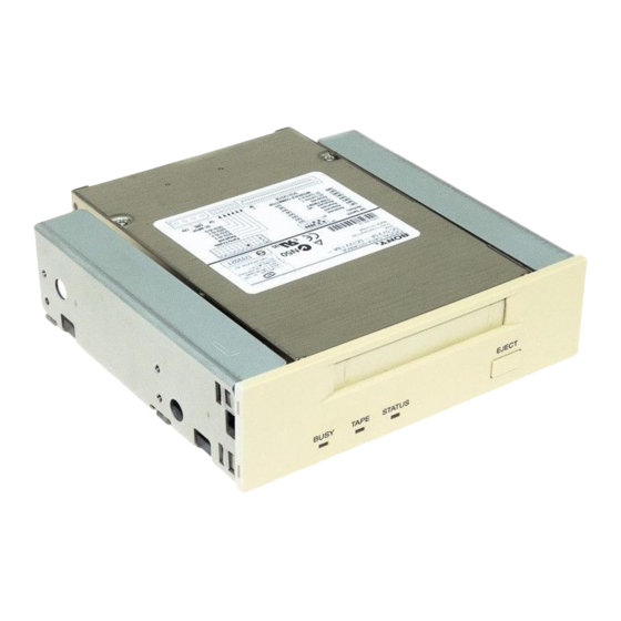
- Page 1 PRODUCT DESCRIPTION MANUAL DDS-4 Tape Drive Model : SDT-10000 : SDT-11000 Ver. 1.2 July, 1999 Sony Corporation...
- Page 2 Difference List ( From Ver.1.1 To Ver.1.2 ) Page Clause Title Modify Delete Model Name SDT-11000 SCSI Signals ( Low-Voltage-Differential Introduction Feature of the drive 2.1.3 Connectors 2.13.1 SCSI Cables and Terminators 2.3.2.2 Burst Data Transfer Rate To and From the SCSI Bus 3-3/3-4 3.1.4 SCSI 68 Pin Connector...
- Page 3 1. Introduction 1 2 3 4 5 1 2 3 4 5 1 2 3 4 5 1 2 3 4 5 1 2 3 4 5 1 2 3 4 5 1 2 3 4 5 1 2 3 4 5 1 2 3 4 5 2.
- Page 4 1. INTRODUCTION 1 INTRODUCTION ......................1-1 1. 1 Features of the drive ..................1-2 1 2 3 4 5 1 2 3 4 5 1 2 3 4 5 1. 2 Reference ......................1-3 1 2 3 4 5 1 2 3 4 5 1 2 3 4 5 1 2 3 4 5 1 2 3 4 5...
- Page 5 Note: The capacity ratings listed above are based on a 150 meter DDS-4 tape cassette. The Sony SDT-10000/SDT-11000 drive is a high capacity data storage device using 4 mm DAT (Digital Audio Tape) technology. The SDT-10000/SDT-11000 drive achieves high data reliability through read-after-write, an additional level of Error Correction Code, and other features.
- Page 6 • Supported Format: DDS-4, DDS-3, DDS-2, DDS , DDS-DC and DCLZ • Fully READ and WRITE compatible with the DDS-4, DDS-3, DDS-2, DDS and DDS-DC format tapes • Burst transfer rate - 14 MB/sec Asynchronous - 40 MB/sec Synchronous •...
- Page 7 European Computer Manufacturers Association 114 Rue du Rhone - CH-1204 Geneva(Switzerland) TEL: (41) 22-735-36-34 FAX: (41) 22-786-52-31 Note 2: Also available from: Global Engineering Documents 2805 McGaw Avenue Irvine, CA 92714 (800) 854-7179 (714) 261-1455 SONY SDT-10000/SDT-11000 DDS Tape Drive 1 - 3...
-
Page 8: Table Of Contents
2. SPECIFICATION 2. 1 PHYSICAL SPECIFICATIONS ................. 2-1 2. 1. 1 Dimensions ....................2-1 2. 1. 1. 1 Mounting Holes ................2-2 2. 1. 2 Weight ......................2-3 2. 1. 3 Connectors ....................2-3 1 2 3 4 5 1 2 3 4 5 2. -
Page 9: Specification
Note: The above dimensions do not include the front panel thickness, eject button and some projecting. 101.6±0.5 mm (4.00 inch) 41.2±0.5 mm 41.2±0.5 mm (1.62 inch) (1.62 inch) 146±0.5 mm (5.75 inch) 101.6±0.5 mm (4.00 inch) 3.8±0.5 mm (0.15 inch) SDT-10000/SDT-11000 Figure 2-1 Dimensions SONY SDT-10000/SDT-11000 DDS Tape Drive 2 - 1... -
Page 10: Mounting Holes
(DEPTH 0.12 in) (0.83 in) (2.36 in) SDT-10000/SDT-11000 Figure 2-2 Mounting Holes Note: Mounting Screw Thread Length 2.5 mm. If the mounting screw thread length is exceeded, damage to the drive may occur. 2 - 2 SONY SDT-10000/SDT-11000 DDS Tape Drive... -
Page 11: Weight
SDT-10000/SDT-11000 - 600 grams (1 lb 5 oz), without a cassette 2. 1. 3 Connectors The SDT-10000/SDT-11000 has a SCSI connector with a power connector at the positions shown in Figure 2-3. All other connectors are for use by Sony’s manufacturing and service facilities only. SCSI & Power Connector SDT-10000/SDT-11000 Figure 2-3 Connector Positions 2. -
Page 12: Environmental Specifications
5 G Peak 3 ms 3 axes, 3 directions Interval 10 seconds Non-operating: No Device Damage Half Sine 90 G Peak 3 ms (30 G Peak 11 ms) 3 axes, 3 directions 2 - 4 SONY SDT-10000/SDT-11000 DDS Tape Drive... -
Page 13: Acoustic Noise
The SDT-10000/SDT-11000 can be installed in three different mounting positions as shown in the figure below. Each position has a maximum tolerance of +/– 10 degrees. 10 ° 10 ° 10 ° 10 ° 10 ° 10 ° Figure 2-4 Mounting Attitude and Tolerance SONY SDT-10000/SDT-11000 DDS Tape Drive 2 - 5... -
Page 14: Performance Specification
The data capacity, data transfer rate and data reliability specifications in this chapter require the media to conform to the DDS-4 Media Specification and also require the drive and media to remain within their respective operating and non- operating environmental specifications. The specifications below also assume that the C3 ECC frame is generated on writing and used as necessary on reading, and further assumes that read-after-write rewrites are used as necessary on writing. -
Page 15: Load Time
For Read-After-Write error correction, each frame can be rewritten up to a maximum of 255 times giving 256 writes of the frame. With N-Group writing, where every group is written a fixed number of times, the upper limit is 8. N-Group writing is not supported by DDS-3 and DDS-4. 2. 3. 10 Definition of Failure A failure is defined as any permanent malfunction of the drive that prevents the user from retrieving data from tape. -
Page 16: Component Life
2. The necessary voltage supplies must be provided. These supplies are Extra Low Voltage SEC for UL and CSA, or Safety Extra Low Voltage for BSI, VDE, and so on, of +5V and +12V DC. 2 - 8 SONY SDT-10000/SDT-11000 DDS Tape Drive... -
Page 17: Installation Requirements
2. 5. 1 Power Requirements SDT-10000/SDT-11000 Current V oltage Max Ripple Typical Maximum (Load/Unload) (Write/Read) 5V +/-5% 100 mV p-p 2.0 A 1.0 A 12V +/-10% 100 mV p-p 1.6 A 0.3 A SONY SDT-10000/SDT-11000 DDS Tape Drive 2 - 9... - Page 18 3. INSTALLATION 3. 1 SCSI Connection/Setting the SCSI ID ..............3-1 3. 1. 1 SCSI ID Number Jumper ................3-2 3. 1. 2 Parity Enable Jumper .................. 3-2 3. 1. 3 Power Connector ..................3-2 3. 1. 4 SCSI 68 pin Connector ................3-3 3.
-
Page 19: Installation
3. 1 SCSI CONNECTION/SETTING THE SCSI ID SCSI 68 pin connector (Non-Shielded) power connector Pin 34 Pin 68 SCSI ID SCSI ID Jumpers Parity Enable Disable Note : = CLOSE/Jumper = OPEN/Jumper not installed Don’t care SONY SDT-10000/SDT-11000 DDS Tape Drive 3 - 1... -
Page 20: Scsi Id Number Jumper
Parity Setting Enable Disable : = OPEN Jumper not installed | = CLOSED Jumper installed 3. 1. 3 Power Connector The power connector is illustrated as Figure 3-1 Figure 3-1: Power Connector 3 - 2 SONY SDT-10000/SDT-11000 DDS Tape Drive... -
Page 21: Scsi 68 Pin Connector
GROUND GROUND GROUND DIFFSENS TERMPWR TERMPWR TERMPWR TERMPWR RESERVED RESERVED GROUND GROUND -ATN +ATN GROUND GROUND -BSY +BSY -ACK +ACK -RST +RST -MSG +MSG -SEL +SEL -C/D +C/D -REQ +REQ -I/O +I/O SONY SDT-10000/SDT-11000 DDS Tape Drive 3 - 3... - Page 22 RESERVED RESERVED GROUND GROUND -ATN GROUND GROUND GROUND -BSY GROUND -ACK GROUND -RST GROUND -MSG GROUND -SEL GROUND -C/D GROUND -REQ GROUND -I/O GROUND -DB(8) GROUND -DB(9) GROUND -DB(10) GROUND -DB(11) GROUND 3 - 4 SONY SDT-10000/SDT-11000 DDS Tape Drive...
-
Page 23: Option Switches (Dip Switch)
3. 2. 1 Termination Power Switch Position 5 of DIP switch is used to set whether SDT-10000/SDT-11000 provides the termination power to pin 17, 18, 51, 52 on SCSI bus, or not. SONY SDT-10000/SDT-11000 DDS Tape Drive 3 - 5... -
Page 24: Data Compression On Switch
Compression disabled at power-on. The host is not allowed to con- trol compression. Compression enabled at power-on. The host is allowed to control compression. Compression enabled at power-on. The host is not allowed to con- trol compression. Table 3-2: Data Compression Switches 3 - 6 SONY SDT-10000/SDT-11000 DDS Tape Drive... - Page 25 4. 5. 2. 1 Operational Problems ..............4-8 4. 5. 2. 2 Read/Write Problems ............... 4-10 4. 5. 3 Clearance for Service ................4-10 4. 5. 4 Packaging for Return to Sony ..............4-10 4. 6 DATA COMPRESSION ................... 4-11...
-
Page 26: Operation
Cleaning Request Flash code 1 Waiting for Reset Waiting for Eject Flash code 2 Illegal FW Tape Selftest Failure Table 4-2: Meaning of each LED indications Flashing-1 0.25sec on / 0.25sec off 0.25sec SONY SDT-10000/SDT-11000 DDS Tape Drive 4 - 1... - Page 27 Flash code 2 Waiting for Reset Flash code 1 Waiting for Eject Flash code 1 Illegal FW Tape Flash code 2 Front Panel Test See 4.3.5.1 Table 4-3: LEDs indications for each state 4 - 2 SONY SDT-10000/SDT-11000 DDS Tape Drive...
-
Page 28: Operator Action
It follows that the Tape Log becomes inaccurate if a cassette is used write-protected, and the media warning cannot be relied on to indicate that the cassette needs to be copied and replaced. SONY SDT-10000/SDT-11000 DDS Tape Drive 4 - 3... -
Page 29: Internal Function
Beginning-of-Tape (BOT) and the Reference area is checked to find the tape format (DDS-4, DDS- 3, DDS-2, DDS and DDS-DC, blank, audio, and so on). If the format is not DDS-4, DDS-3, DDS-2, DDS and DDS- DC, the drive rewinds the tape to BOT and awaits either a WRITE, Partitioning MODE SELECT or an UNLOAD command. -
Page 30: Front Panel Test
Unit (MSFU). The confidence in this decision is intended to be 95%. The MSFU is identified and displayed on the front panel as shown above section 4. 3. 4. For the details of Diagnostics, see section 7. SONY SDT-10000/SDT-11000 DDS Tape Drive 4 - 5... -
Page 31: Normal Status Display
More than 1 ECC C3 error correction per 128 groups read Note: Media warning is calculated as an average value of 1024 groups of data (either Read or Write) 1024 Groups of data is approximately 390 MB. 4 - 6 SONY SDT-10000/SDT-11000 DDS Tape Drive... -
Page 32: Tape Format
The SDT-10000/SDT-11000 is an implementation of the Digital Data Storage (DDS) format, a standard developed by Sony and Hewlett-Packard for 4mm data storage drives. It incorporates the error correction techniques used in DAT audio drives with additional techniques specifically designed to provide the optimum level of data integrity. These extra... -
Page 33: Maintenance, Troubleshooting And Service
0.5 seconds 4. 5. 2 Troubleshooting Guide Problems encountered while operating the Sony SDT-10000/SDT-11000 tape drive fall into two categories: Opera- tional problems and Read/Write problems. Operational problems include any conditions that prevent the tape drive from operating. Operational problems usually are discovered the first time the drive is installed on a system or when the system configuration is changed or physically moved. - Page 34 If Tape is still in the drive after following the above procedure. The drive has a serious problem and should be returned to Sony for repair with the tape in place. Note: If it is absolutely mandatory that the tape cassette be removed prior to returning the drive for repair the following Emergency Cassette Removal procedure should be followed.
-
Page 35: Read/Write Problems
Load a new tape in the drive. Retry the operation. Note: If these steps do not correct the problem the drive may be defective and should be returned to Sony for service. 4. 5. 3 Clearance for Service All servicing is performed only after removal of the SDT-10000/SDT-11000 from its mounting. -
Page 36: Data Compression
Data compression is a very powerful and reliable method increasing data capacity and transfer rate without compromis- ing data reliability. SONY SDT-10000/SDT-11000 DDS Tape Drive 4 - 11... - Page 37 5. SCSI INTERFACE 5. 1 INTRODUCTION ......................5-1 5. 1. 1 Overview of the SCSI Interface ..............5-1 5. 1. 2 Supported Messages .................. 5-1 5. 1. 3 Supported and Unsupported Commands ..........5-2 5. 2 SCSI BUS OPERATION .................... 5-3 5.
-
Page 38: Scsi Interface
Extended Message - Synchronous Data Transfer Request Identify (w/ & w/o disconnect) Initiator Detected Error Message Parity Error Message Reject No Operation Restore Pointers Save Data Pointer For implementation details on these messages, see the Message Specification section. SONY SDT-10000/SDT-11000 DDS Tape Drive 5 - 1... -
Page 39: Supported And Unsupported Commands
REPORT DENSITY SUPPORT REPORT LUNS REQUEST BLOCK ADDRESS REQUEST SENSE RESERVE UNIT REWIND SEEK BLOCK SEND DIAGNOSTIC SPACE TEST UNIT READY VERIFY WRITE WRITE BUFFER WRITE FILEMARKS Table 5-1: Supported SCSI Commands 5 - 2 SONY SDT-10000/SDT-11000 DDS Tape Drive... -
Page 40: Scsi Bus Operation
SEL and completing the selection phase, the Host asserts the ATN line. The Host then releases SEL and BSY to allow the target to assume control of the SCSI bus. By asserting ATN, the host indicates that the target should go to a MESSAGE OUT phase. SONY SDT-10000/SDT-11000 DDS Tape Drive 5 - 3... - Page 41 Identify message via a MESSAGE OUT phase. If the Host, however, performs this action during a DATA phase, it is possible that the target will not notice the change in Disconnect permission status until past the end of the current bus phase. 5 - 4 SONY SDT-10000/SDT-11000 DDS Tape Drive...
-
Page 42: Message Specification
MESSAGE REJECT and will continue. A Synchronous Data Transfer Request message has the following format: Byte Value Description Extended message Extended message length SYNCHRONOUS DATA TRANSFER REQUEST code Transfer period (m times 4 nanoseconds) REQ/ACK offset Table 5-3: Synchronous Data Transfer Request SONY SDT-10000/SDT-11000 DDS Tape Drive 5 - 5... - Page 43 After successfully completing the MESSAGE OUT phase, the target shall respond with the proper SDTR message. If an abnormal condition prevents the target from returning an appropriate response, both devices shall go to asynchronous data transfer mode for data transfers between the two devices. 5 - 6 SONY SDT-10000/SDT-11000 DDS Tape Drive...
-
Page 44: Wide Data Transfer Request
(1) after a hard reset condition (2) after a BUS DEVICE RESET message and (3) after a power cycle SONY SDT-10000/SDT-11000 DDS Tape Drive 5 - 7... - Page 45 BUS FREE phase. The initiator shall accept such action as aborting the negotiation and both devices shall go to eight-bit data transfer mode for data transfers between the two devices. 5 - 8 SONY SDT-10000/SDT-11000 DDS Tape Drive...
-
Page 46: Save Data Pointer (02H)
When received as a target the unit will attempt to retry the phase and if unsuccessful then enter the status phase reporting CHECK CONDITION with the sense key set to COMMAND ABORTED. SONY SDT-10000/SDT-11000 DDS Tape Drive 5 - 9... -
Page 47: Abort (06H)
A BUS DEVICE RESET message should be used to reset the drive, rather than a hard reset, as this will only reset the drive rather than all the devices on the bus. Due to the catastrophic nature of this command, it should be used cautiously in a multi-initiator system. 5 - 10 SONY SDT-10000/SDT-11000 DDS Tape Drive... -
Page 48: Ignore Wide Residue (23H)
Invalid data bits Ignore 16-bit transfers Reserved DB (15-8) 02-FFh Reserved Table 5-6: Ignore Field Even though a byte is invalid its corresponding parity bit shall be valid for the value transferred. SONY SDT-10000/SDT-11000 DDS Tape Drive 5 - 11... -
Page 49: Status Specification
The Host may load the tape when the unit is offline so long as the tape has been prevented from being ejected via the PREVENT/ALLOW MEDIA RE- MOVAL command. 5 - 12 SONY SDT-10000/SDT-11000 DDS Tape Drive... - Page 50 RESERVATION CONFLICT: This status is returned by the drive whenever the host or another SCSI device attempts to access the drive if it has been reserved via the RESERVE UNIT command. SONY SDT-10000/SDT-11000 DDS Tape Drive 5 - 13...
- Page 51 6. 06. 6 Tape Log Page (Sony Unique)..............6-25 6. 06. 7 Tape Capacity Log Page ................6-27 6. 06. 8 Drive Usage Log Page (Sony Unique) ............ 6-28 6. 06. 9 Data Compression Transfer Log Page ........... 6-30 6. 07 MODE SELECT 15h..................... 6-32 6.
- Page 52 At the termination of each command, the target sends a status byte to the initiator. See the section on Status for more details. All SDT-10000/SDT-11000 SONY unique commands are in Group 7. Group 7 commands are 6 bytes long.
- Page 53 11000 does NOT receive an IDENTIFY message on selection then it WILL check the LUN field in the CDB and expect it to be zero. If it isn’t the unit will return a CHECK CONDITION status with an ILLEGAL REQUEST sense key set. 6 - 2 SONY SDT-10000/SDT-11000 DDS Tape Drive...
-
Page 54: Erase 19H
If the bit is set to 1, the drive will write EOD from the current logical position till the end of current partition. If the bit is set to 0, the drive will write only 300 frames (for DDS-1) or 450 frames (for DDS-2, DDS-3 or 600 frames (DDS-4)) of EOD from the current logical position. SONY SDT-10000/SDT-11000 DDS Tape Drive... -
Page 55: Inquiry 12H
When the CmdDT bit is set to one, the page or operation field specifies the SCSI operation code for which the drive shall return support data. EVPD: The Enable Vital Product Data (EVPD) bit of one specifies that the drive returns the optional vital product data specified by the page code field. 6 - 4 SONY SDT-10000/SDT-11000 DDS Tape Drive... - Page 56 The product serial number field contains ASCII data that is vendor-specific. The least significant ASCII character of the number shall appear as the last byte of a successful data transfer. SONY SDT-10000/SDT-11000 DDS Tape Drive 6 - 5...
- Page 57 Reserved (00h) CDB size (m-5) CDB usage data Support: The drive supports the tested SCSI operation code in conformance with a SCSI standard. The data format conforms to the definition in table. 6 - 6 SONY SDT-10000/SDT-11000 DDS Tape Drive...
- Page 58 Peripheral Qualifier set to 011b the target is not capable of supporting a physical device on this logical unit and Peripheral Device Type set to 1Fh unknown device type. SONY SDT-10000/SDT-11000 DDS Tape Drive 6 - 7...
- Page 59 Vendor Identification: This field contains eight bytes of ASCII data identifying the vendor of the product as “SONY”. This and the next two fields are left-aligned with the unused bytes at the end of the fields and filled with space characters (20h).
-
Page 60: Load/Unload 1Bh
If this bit is set, status is returned as soon as the load or unload operation is initiated. Otherwise, the status is returned after the operation has completed. Re-Ten: If this bit is set, the drive winds to EOM then rewinds to BOM before starting a normal loading sequence. SONY SDT-10000/SDT-11000 DDS Tape Drive 6 - 9... - Page 61 Front Panel EJECT button. If no cassette is in drive, both LOAD and UNLOAD will return a CHECK CONDITION status with NOT READY sense key set. 6 - 10 SONY SDT-10000/SDT-11000 DDS Tape Drive...
-
Page 62: Locate 2Bh
BT bit. Partition: The Partition field specifies which partition to select if the CP bit is one. Refer to the MODE SELECT command, Medium Partition page for additional information about partitioning. SONY SDT-10000/SDT-11000 DDS Tape Drive 6 - 11... -
Page 63: Log Select 4Ch
If the SP bits is set, the command will be terminated with CHECK CONDITION status with the sense key set to ILLEGAL REQUEST, and an additional sense code of INVALID FIELD IN CDB. 6 - 12 SONY SDT-10000/SDT-11000 DDS Tape Drive... - Page 64 The purpose of the LOG SELECT command is to allow the initiator to modify and initialize parameters within the logs supported by the device. However in this case, access to individual parameters within log pages is not supported and so initiator is restricted to resetting complete log pages only. SONY SDT-10000/SDT-11000 DDS Tape Drive 6 - 13...
- Page 65 REQUEST and an additional sense code of ILLEGAL FIELD IN PARAMETER LIST. The same status will be re- turned if an unsupported Page Code appears in any header or if the specified page cannot cleared. 6 - 14 SONY SDT-10000/SDT-11000 DDS Tape Drive...
-
Page 66: Log Sense 4Dh
If the SP bit is set, the command will be terminated with CHECK CONDITION status with the sense key set to ILLEGAL REQUEST, and an additional sense code of INVALID FIELD IN CDB. SONY SDT-10000/SDT-11000 DDS Tape Drive 6 - 15... - Page 67 The Default Cumulative Values are the values to which each parameter gets initialized on a reset condition as described above. See description of individual pages/parameters below for more details. 6 - 16 SONY SDT-10000/SDT-11000 DDS Tape Drive...
- Page 68 Supported Log Pages Write Error Counter Page Read Error Counter Page 1A8h (max) Last n Error Events Page Tape Log Page (Sony Unique) 5Eh (DDS-3 and DDS-4) Tape Capacity Log Page 154h Drive Usage Page (Sony Unique) Data Compression Transfer Log Page...
-
Page 69: The Log
A Page Length value that results in the truncation of any parameter shall cause the target to terminate the command with CHECK CONDITION status. The sense key shall be set to ILLEGAL REQUEST and the additional sense code shall be set to INVALID FIELD IN PARAMETER LIST. 6 - 18 SONY SDT-10000/SDT-11000 DDS Tape Drive... -
Page 70: The Log Parameter Descriptor
DS: The DS bit-field informs the initiator that savable parameters are disabled (i. e. not supported), and should always be 1. If it is 0 the command will terminate with CHECK CONDITION status with sense key set to ILLEGAL REQUEST and additional sense code of ILLEGAL FIELD IN PARAMETER LIST. SONY SDT-10000/SDT-11000 DDS Tape Drive 6 - 19... - Page 71 Note: If any of the other bit-fields in the control byte are set then the command will terminate with a CHECK CONDI- TION status with a sense key of ILLEGAL REQUEST and an additional sense code of INVALID FIELD IN PARAMETER LIST. 6 - 20 SONY SDT-10000/SDT-11000 DDS Tape Drive...
-
Page 72: Supported Log
Supported Log Pages Write Error Counter Page Read Error Counter Page 1A8h (max) Last n Error Events Page Tape Log Page (Sony Unique) 5Eh (DDS-3 and DDS-4) Tape Capacity Log Page Drive Usage Page (Sony Unique) 154h Data Compression Transfer Log Page Table 6-10: Supported Log pages A description of each supported log page is given below. -
Page 73: Write And Read Error Counters
Page Length (n) (LSB) (MSB) Parameter Code (LSB) DU (0) DS (1) TSD (0) ETC (0) TMC (00) Reserved LP (0) Parameter Length (m) (MSB) Parameter Value (LSB) Table 6-12: Write/Read Error counters page 6 - 22 SONY SDT-10000/SDT-11000 DDS Tape Drive... - Page 74 0003h Total Errors Corrected FFFFh (Soft Errors) 0004h Total Times Correction FFFFFFFFh Algorithm Processed 0005h Total Groups Processed FFFFFFFFh 0006h Total Errors Uncorrected FFFFh (Hard Errors) Table 6-14: Error Counter parameter codes SONY SDT-10000/SDT-11000 DDS Tape Drive 6 - 23...
-
Page 75: Last N Error Events List
When the log page becomes full, no more entries will be added until the log is cleared (using one of the methods described previously) or a reset occurs. The current cumulative values will be returned regardless of the page control field in the LOG SENSE CDB. 6 - 24 SONY SDT-10000/SDT-11000 DDS Tape Drive... -
Page 76: Tape Log Page (Sony Unique)
6. COMMAND SPECIFICATION LOG SENSE 6. 06. 6 Tape Log Page (Sony Unique) This page is a Sony unique page which provides information on the tape currently being used. This log cannot be cleared and has the following format: Byte... - Page 77 Current number of RAW Retries 003h Current number of Groups Read 004h Current number of ECC-3 Retries 005h Previous number of Groups Written 4 (DDS-3 and DDS-4) 006h Previous number of RAW Retries 007h Previous number of Groups Read 4 (DDS-3 and DDS-4) 008h...
-
Page 78: Tape Capacity Log Page
Remaining capacity, partition 1 (kilobytes), For a single partition tape, it will be zero. 0003 Maximum capacity , partition 0 (kilobytes) 0004 Maximum capacity, partition 1 (kilobytes). For a single partition tape, it will be zero. SONY SDT-10000/SDT-11000 DDS Tape Drive 6 - 27... -
Page 79: Drive Usage Log Page (Sony Unique)
6. COMMAND SPECIFICATION LOG SENSE 6. 06. 8 Drive Usage Log Page (Sony Unique) This page is a SONY unique page which provides information on the drive currently being used. This log cannot be cleared and has the following format: Byte... - Page 80 STOP FF TENSION OFF 0x10 0x35 STOP REW 0x11 0x36 ASSERT 0x17 0x37 RELEASE UNTHREAD 0x20 0x38 RE ASSERT STOP 0x21 0x39 STOP FWD EJECT 0x22 0x3A STOP RVS MD INITIALIZE 0x2A SONY SDT-10000/SDT-11000 DDS Tape Drive 6 - 29...
-
Page 81: Data Compression Transfer Log Page
(MSB) Parameter Code (n) (LSB) DU (0) DS (1) TSD (0) ETC (0) TMC (00) Reserved LP (0) Parameter Length (04h) (MSB) Parameter Value (LSB) Table 6-23: Data Compression Transfer Log Page 6 - 30 SONY SDT-10000/SDT-11000 DDS Tape Drive... - Page 82 Similarly, the host can calculate instantaneous compression ratio achieved by the drive for a particular read or write command: logical entity size instantaneous compression ratio = physical entity size SONY SDT-10000/SDT-11000 DDS Tape Drive 6 - 31...
-
Page 83: Mode Select 15H
A zero parameter list length indicates that no data is transferred. The Parameter List length must be a value which coincides with header, block descriptor or page boundaries. If this does not occur then the drive will return a CHECK CONDITION status with an ILLEGAL REQUEST sense key set. 6 - 32 SONY SDT-10000/SDT-11000 DDS Tape Drive... - Page 84 Reserved Reserved Reserved Buffered Mode Speed (00h) Block Descriptor Length (08h) Density Code (MSB) Number of Blocks (00 00 00h) (LSB) Reserved (MSB) Block Length (LSB) Table 6-24: MODE SELECT parameter list SONY SDT-10000/SDT-11000 DDS Tape Drive 6 - 33...
- Page 85 Note: 00h - Default: The use of the word “Default” is SCSI specific. It instructs the drive to use its default or only density. Therefore the drive uses its only density of 13h. 13h is the value that has been allocated for use by DDS devices by the ANSI SCSI Committee (X3T9.2). 6 - 34 SONY SDT-10000/SDT-11000 DDS Tape Drive...
-
Page 86: Disconnect-Reconnect Page
Disconnect-Reconnect Page 0Ch+10h=1Ch Data Compression Control Page 0Ch+10h=1Ch Device Configuration Page 0Ch+10h=1Ch Medium Partitions Parameter Page 0Ch+0Ch=18h Information Exception Control 0Ch+0Ch=18h Return All Pages 0Ch+10h+10h+10h+0Ch=48h Table 6-27: Supported MODE SELECT Page Codes SONY SDT-10000/SDT-11000 DDS Tape Drive 6 - 35... - Page 87 The drive also returns a CHECK CONDITION status with an ILLEGAL REQUEST sense key if the Host sends an unsupported Page Code, a page field with values that are not supported or are not changeable. In this case, no parameters will have been changed by the command. 6 - 36 SONY SDT-10000/SDT-11000 DDS Tape Drive...
- Page 88 This field is not supported by the drive and if set a CHECK CONDITION status is returned with an ILLEGAL REQUEST sense key set. Report Count: This field is not supported by the drive and if set a CHECK CONDITION status is retuned with an ILLEGAL REQUEST sense key set. SONY SDT-10000/SDT-11000 DDS Tape Drive 6 - 37...
- Page 89 Buffer Full Ratio, Buffer Empty Ratio, Bus Inactivity Limit and Connect Time Limit fields are not supported by the drive if set to non-zero values a CHECK CONDITION status is returned with ILLEGAL REQUEST sense key set. 6 - 38 SONY SDT-10000/SDT-11000 DDS Tape Drive...
- Page 90 If DTDC is nonzero and the maximum burst size is nonzero the target shall return CHECK CONDITION status. The sense key shall be set to ILLEGAL REQUEST and the additional sense code set to ILLEGAL FIELD IN PARAMETER LIST. SONY SDT-10000/SDT-11000 DDS Tape Drive 6 - 39...
-
Page 91: Data Compression Control Page
The SDT-10000/SDT-11000 has the capability to decompress data and will set this bit to a one. DDE: A data decompression enable (DDE) bit of one indicates that data decompression is enabled. Data Compression capability can not be turned off on SDT-10000/SDT-11000. 6 - 40 SONY SDT-10000/SDT-11000 DDS Tape Drive... - Page 92 Therefore, the drive will override the value in the decompression field (if is set to zero) for a subsequent read operation when DCLZ compressed data is detected on the media. SONY SDT-10000/SDT-11000 DDS Tape Drive 6 - 41...
- Page 93 A value of zero shall indicate that the data encountered on the medium during the most recent read operation was uncompressed. 6 - 42 SONY SDT-10000/SDT-11000 DDS Tape Drive...
-
Page 94: Device Configuration Page
The Change Active Partition bit, then set to one, indicates that the logical partition is changed to the one specified by the Active Partition Field. This is a feature supported by the drive and is discussed below. SONY SDT-10000/SDT-11000 DDS Tape Drive 6 - 43... - Page 95 The value of this field indicates the number of times a group will repeatedly be written to tape. The default is zero repetitions. This feature may be used to performance match the drive with the Host. A decode of the field is shown below: This field will not be used on DDS-3 and DDS-4. Number of Repetitions 0 (Default)
- Page 96 This field shall always be set to zero so that the drive will use its default EOD definition to detect and generate EOD. Any other value will cause the drive to return a CHECK CONDITION status with an ILLEGAL REQUEST sense key set. SONY SDT-10000/SDT-11000 DDS Tape Drive 6 - 45...
- Page 97 The SDT-10000/SDT-11000 supports the Data Compression Page and that page should be used instead of this field to control Data Compression. This field is not supported by the drive and if set a CHECK CONDITION status is returned with an ILLEGAL REQUEST sense key set. 6 - 46 SONY SDT-10000/SDT-11000 DDS Tape Drive...
-
Page 98: Medium Partitions Parameter Page
For issuing Mode Select with Additional Partition Defined = 0, the command will function properly even when the Parameter List Length of the CDB is set to 14h. In this case, it is necessary to set the Parameter Length to 6h. SONY SDT-10000/SDT-11000 DDS Tape Drive 6 - 47... - Page 99 (Logical) EOM = End-of-Media (Physical) EOP = End-of-Partition (Logical) EOT = End-of-Tape (Logical) Note: The System area consists of three sub-sections: Reference Area System Area Vendor Group Figure 6-1: Tape Partition Layout 6 - 48 SONY SDT-10000/SDT-11000 DDS Tape Drive...
- Page 100 If the Additional Partitions Defined and Partition Size fields are set to zero the drive will initialize the tape as Partition 0, spanning the whole length of the tape. Partition 0 size is only valid during MODE SENSE and is ignored during MODE SELECT Remaining Capacity goes to P.0. SONY SDT-10000/SDT-11000 DDS Tape Drive 6 - 49...
-
Page 101: Mode Sense 1Ah
The drive returns the default values of the mode parameters. Page Default Values field not supported are set to zero by the drive. Not supported by the drive Saved Values Table 6-34: Page Control field values 6 - 50 SONY SDT-10000/SDT-11000 DDS Tape Drive... - Page 102 Allocation Length must be set to 0Ch. The value of the Page Control Field is then not checked by the drive and may be set to any value. SONY SDT-10000/SDT-11000 DDS Tape Drive 6 - 51...
- Page 103 8, which specifies the length in bytes of the following Block Descriptor. The drive only returns a single Block Descriptor. When the DBD is one, the Block Descriptor Length in the parameter header is set to 0. 6 - 52 SONY SDT-10000/SDT-11000 DDS Tape Drive...
- Page 104 6. COMMAND SPECIFICATION MODE SENSE Destiny Code: The drive returns 13h for DDS-1, 24h for DDS-2, 25h for DDS-3, or 26h for DDS-4 in the Density Code field. (Assigned by ANSI SCSI Committee X3T9.2) Number of Blocks: The Number of Blocks field is zero, indicating that an unspecified (or unknown) number of the remaining logical blocks on the tape may have the media characteristics specified by the Block Descriptor.
-
Page 105: Prevent Allow Medium Removal 1Eh
This situation remains until the Prevent bit is set to zero. When this bit is set to zero, the drive ejects the cassette following completion of an UNLOAD. The Eject button is also re-enabled. 6 - 54 SONY SDT-10000/SDT-11000 DDS Tape Drive... -
Page 106: Read 08H
(residue) between the requested number of blocks and the actual number of blocks read. No more than Transfer Length bytes are transferred to the initiator and the tape is logically positioned after the last block transferred (EOM side). SONY SDT-10000/SDT-11000 DDS Tape Drive 6 - 55... - Page 107 For both a Filemark and a reported Save-Set Mark, if the Fixed bit is one, the Information bytes in the REQUEST SENSE data are set to the difference residue between the requested Transfer Length and the actual number of blocks read (not including the Filemark or Save-Set Mark). 6 - 56 SONY SDT-10000/SDT-11000 DDS Tape Drive...
- Page 108 HARDWARE ERROR. BLANK CHECK: If EOD (End-of-Data) was encountered during a read, the sense key is BLANK CHECK, the Valid bit is set and the Information bytes contain the residue count. SONY SDT-10000/SDT-11000 DDS Tape Drive 6 - 57...
-
Page 109: Read Block Limits 05H
One (1) byte is the minimum and 16 Megabytes - 1 byte is the maximum block size which the unit can support. Byte Reserved (MSB) Minimum Block Length Limit (FF FF FFh) (LSB) (MSB) Minimum Block Length Limit (00 01h) (LSB) Table 6-37: READ BLOCK LIMITS Data 6 - 58 SONY SDT-10000/SDT-11000 DDS Tape Drive... -
Page 110: Read Buffer 3Ch
The drive terminates the DATA IN phase when Allocation Length bytes of header plus data have been transferred or when the header and all available data have been transferred to the initiator, whichever is less. The four-byte READ BUFFER header is followed by data bytes from the drive’s data buffer. SONY SDT-10000/SDT-11000 DDS Tape Drive 6 - 59... - Page 111 The Alloca- tion Length must be greater than four (except in data only mode), else the drive will return a CHECK CONDITION status with an ILLEGAL REQUEST sense key set. 6 - 60 SONY SDT-10000/SDT-11000 DDS Tape Drive...
-
Page 112: Read Position 34H
First Block Location shall include data block only. The BT bit of ZERO requests the drive to return the First Block Location are a SCSI Logical Block Address (data blocks, File-marks and Save Set Marks are counted.) SONY SDT-10000/SDT-11000 DDS Tape Drive 6 - 61... - Page 113 READ or WRITE command is issued. See BT field for description of Logical Block Address. Note that the Logical Block Address at BOT/P is 0. 6 - 62 SONY SDT-10000/SDT-11000 DDS Tape Drive...
- Page 114 File Number: File Number reports the number of file-marks between beginning-of-partition and the current logical position. Set Number: Set Number reports the number of set-marks between beginning-of-partition and the current logical position. SONY SDT-10000/SDT-11000 DDS Tape Drive 6 - 63...
-
Page 115: Receive Diagnostic Results 1Ch
Code of DIAGNOSTIC FAILURE set on completion of a SEND DIAGNOSTIC, then the Host should issue a RE- CEIVE DIAGNOSTIC RESULTS command to receive the eight bytes of data indicating the actual failure and the Most Suspect Unit (MSU). 6 - 64 SONY SDT-10000/SDT-11000 DDS Tape Drive... - Page 116 If the Host issued a SEND DIAGNOSTIC with the PF bit set and a Page Code of 81h, the drive returns the following four bytes of page header, then five bytes of diagnostic results. Byte Page Code (81h) Reserved (MSB) Page Length (00 05h) (LSB) Table 6-43: RECEIVE DIAGNOSTICS page header SONY SDT-10000/SDT-11000 DDS Tape Drive 6 - 65...
- Page 117 The content of these bytes depends on the test being run. See the Diagnostics section. Test Number: This is the test number to which the message applies (if a test fails within a sequence, the individual test number will be returned). 6 - 66 SONY SDT-10000/SDT-11000 DDS Tape Drive...
-
Page 118: Release Unit 17H
Third-Party reservation option by the initiator that is requesting the release and for the same SCSI device as specified in the Third-Party Device ID field. SONY SDT-10000/SDT-11000 DDS Tape Drive 6 - 67... -
Page 119: Report Density Support
DENSITY SUPPORT data block. The Density support data blocks shall be in numerical ascending order of the primary density code value for each block. REPORT DENSITY SUPPORT header Byte Available Density Support Length (00h) (D2h (MEDIA=0) or 36 (MEDIA=1)) Reserved Reserved 6 - 68 SONY SDT-10000/SDT-11000 DDS Tape Drive... - Page 120 DENSITY NAME (DDS1) DESCRIPTION (2 GB) PRIMARY DENSITY CODE (24h) SECONDARY DENSITY CODE (13h) WRTOK (1) DUP (0) DEFLT (1) Reserved (00h) Reserved Reserved (MSB) BITS PER MM (00 09 62h) (LSB) SONY SDT-10000/SDT-11000 DDS Tape Drive 6 - 69...
- Page 121 (LSB) (MSB) MEDIA WIDTH (00 28h) (LSB) (MSB) TRACKS (00 01h) (LSB) (MSB) CAPACITY (00 00 2E E0h) (LSB) ASSIGNING ORGANIZATION (SONY) DENSITY NAME (DDS3) DESCRIPTION (12 GB) PRIMARY DENSITY CODE (26h) 6 - 70 SONY SDT-10000/SDT-11000 DDS Tape Drive...
- Page 122 If neither the Primary or Secondary density code is zero and the DEFLT bit is one, the logical unit shall accept a Mode Select density code of 00h as equivalent to the Primary and Secondary density code. SONY SDT-10000/SDT-11000 DDS Tape Drive 6 - 71...
- Page 123 “good” condition, and that “normal” data and block size are used. This value is in units of megabytes (10000000 bytes). The logical unit does not guarantee that this space is actually available in all cases. 6 - 72 SONY SDT-10000/SDT-11000 DDS Tape Drive...
-
Page 124: Report Luns A0H
If the allocation length in the command descriptor block is too small to transfer information about all configured logical units, the LUN list length value shall not be adjusted to reflect the truncation. SONY SDT-10000/SDT-11000 DDS Tape Drive 6 - 73... -
Page 125: Request Block Address 02H
Transfer Length of 3 bytes is used. Byte Logical Block Address (MSB) Logical Block Address Logical Block Address (LSB) Table 6-46: Request Block Address Data Format The Logical Block Address fields contain the current tape position block number. 6 - 74 SONY SDT-10000/SDT-11000 DDS Tape Drive... -
Page 126: Request Sense 03H
The Allocation Length specifies the maximum number of sense bytes to be returned. The drive terminates the transfer when the Allocation Length bytes have been transferred or when all available sense data has been trans- ferred to the Host, whichever is less. SONY SDT-10000/SDT-11000 DDS Tape Drive 6 - 75... - Page 127 Additional Sense Code Qualifier Field Replaceable Unit code SKSV Reserved (MSB) Read/WriteData Errr Counter (LSB) (MSB) Remaining Tape (LSB) Reserved Reserved Reserved Table 6-47: Error Codes 70h and 71h Sense Data Format 6 - 76 SONY SDT-10000/SDT-11000 DDS Tape Drive...
- Page 128 Code Qualifiers (Byte 13) supported by the SDT-10000/SDT-11000 are listed in a table beginning on the following page. The following Table shows the REQUEST Sense Keys and the Additional Sense Key (Byte 12) and the Additional Sense Key Qualifier (Byte 13) supported by the SDT-10000/SDT-11000: SONY SDT-10000/SDT-11000 DDS Tape Drive 6 - 77...
- Page 129 This field indicates which byte of the Command Descriptor Block or of the Parameter List data was in error. Bytes are numbered from zero. When a multiple byte field is in error, the pointer points to the most significant byte of the field. 6 - 78 SONY SDT-10000/SDT-11000 DDS Tape Drive...
- Page 130 6. COMMAND SPECIFICATION REQUEST SENSE If the SKSV bit is zero, then the Field Pointer Bytes take the SONY Unique format as shown below: Byte SKSV(0) Reserved Runtime Error Code Status Byte (00h) Table 6-49: Error Code and Status Bytes Runtime Error Code: This field is part of the internal protocol and contains the Runtime (error set 0) Error code.
- Page 131 Also during the auto load following a tape insertion. 3A 00 MEDIUM NOT PRESENT - This status is returned for all tape motion commands when there is no media within the drive. Table 6-50: Sense Key Descriptions (1/6) 6 - 80 SONY SDT-10000/SDT-11000 DDS Tape Drive...
- Page 132 DECOMPRESSION EXCEPTION LONG ALGORITHM ID - ALGORITHM ID > 255 52 00 CARTRIDGE FAULT - Possible causes: Illegal media recognition switch pattern, Reel motors will not turn Table 6-50: Sense Key Descriptions (2/6) SONY SDT-10000/SDT-11000 DDS Tape Drive 6 - 81...
- Page 133 MEDIA LOAD OR EJECT FAILED - Unable to complete Load or Unload operation successfully. Possible causes: Mechanical problems or Read/Write failure in test sec- tion of the media Table 6-50 Sense Key Descriptions (3/6) 6 - 82 SONY SDT-10000/SDT-11000 DDS Tape Drive...
- Page 134 NOT READY TO READY TRANSITION, MEDIUM MAY HAVE CHANGED 29 00 POWER ON, RESET, OR BUS DEVICE RESET OCCURRED 29 80 Drive Failed Power-on test or Diagnostic - (SONY Unique) 2A 00 PARAMETERS CHANGED 2A 01 MODE PARAMETERS CHANGED - Issued to all other initiators after one initiator changes any Mode Parameter.
- Page 135 4E 00 OVERLAPPED COMMANDS ATTEMPTED - Host issued a new command to the drive while a previous command was being executed. EQUAL. Not supported by the SDT-10000/SDT-11000 Table 6-50: Sense Key Descriptor (5/6) 6 - 84 SONY SDT-10000/SDT-11000 DDS Tape Drive...
- Page 136 BUS DEVICE RESET message directly following the IDENTIFY mes- sage. This forces the drive to do a hard reset. If the fault persists, the host should deny access to the drive. SONY SDT-10000/SDT-11000 DDS Tape Drive 6 - 85...
-
Page 137: Reserve Unit 16H
An initiator that holds a current reservation may modify that reservation e.g., switch third-parties by issuing another RESERVE UNIT command to the drive. If the logical unit has previously been reserved by another initiator, the target returns a RESERVATION CONFLICT status. 6 - 86 SONY SDT-10000/SDT-11000 DDS Tape Drive... -
Page 138: Rewind 01H
When this bit is set, the drive writes any remaining buffered data followed by an EOD marker to tape. It then returns status to the Host before beginning the actual rewind operation. If the Immed bit is not set, status will be returned after the rewind has completed. SONY SDT-10000/SDT-11000 DDS Tape Drive 6 - 87... -
Page 139: Seek Block (0Ch)
If the Immed bit is 1 then the drive will report “COMMAND COMPLETE” to the Initiator upon acceptance of the command. Logical Block Address: The Block Address of the desired position. 6 - 88 SONY SDT-10000/SDT-11000 DDS Tape Drive... -
Page 140: Send Diagnostic 1Dh
This field provides the count of the number of Parameter List bytes which will be transferred in the DATA OUT phase. These bytes describe the test that is to be run. This field must be set to zero if the SelfTest bit is set. SONY SDT-10000/SDT-11000 DDS Tape Drive 6 - 89... - Page 141 CHECK CONDITION status with an ILLEGAL REQUEST sense key set. This page Code instructs the drive to execute the five bytes of diagnostic test that follow the four bytes of header. 6 - 90 SONY SDT-10000/SDT-11000 DDS Tape Drive...
- Page 142 REQUEST DIAGNOSTIC command. Refer to section 7, Drive Diagnostics for more detailed information about the supported diagnostic tests and test opera- tions. SONY SDT-10000/SDT-11000 DDS Tape Drive 6 - 91...
-
Page 143: Space 11H
Filemark, Setmark, EOD, BOM/P or EOM/P. A SPACE N filemarks will halt on the Nth filemark or on any occurrence of setmark, EOD, BOM/P or EOM/P, and so on. Within the Sense data, the fields will be set as described on the following table. 6 - 92 SONY SDT-10000/SDT-11000 DDS Tape Drive... - Page 144 Medium Error EOM/P Detected Setmarks Blank Check No Sense BOM/P Detected Phy. EOT Medium Error EOM/P Detected No Sense BOM/P Detected Phy. EOT Medium Error EOM/P Detected Table 6-54: SPACE CHECK CONDITION results SONY SDT-10000/SDT-11000 DDS Tape Drive 6 - 93...
- Page 145 If BOT is detected while spacing over blocks or marks in the reverse direction, the EOM bit is set in extended sense. The Valid bit is set to one and the Information bytes to the difference (residue) between the requested count and the actual number of blocks or Filemarks spaced over. 6 - 94 SONY SDT-10000/SDT-11000 DDS Tape Drive...
-
Page 146: Test Unit Ready 00H
Tape Unloading 02 Not Ready 04 00 LOGICAL UNIT NOT READY Tape Unloaded 02 Not Ready 04 00 LOGICAL UNIT NOT READY (but retained in drive) Table 6-55: TEST UNIT READY results SONY SDT-10000/SDT-11000 DDS Tape Drive 6 - 95... -
Page 147: Verify 13H
SENSE and the Information Bytes are set to the difference (residue) between the requested Verification length and the actual block length, or in Blocked Mode, the difference (residue) between the requested number of blocks and the actual number of blocks verified. 6 - 96 SONY SDT-10000/SDT-11000 DDS Tape Drive... - Page 148 (residue) between the requested Verification Length and the actual number of bytes verified. Filemarks and Save-Set Marks are considered to have a byte count of zero, though this will not cause the ILI bit to be set. SONY SDT-10000/SDT-11000 DDS Tape Drive 6 - 97...
-
Page 149: Write 0Ah
CHECK CONDITION status. Within the Sense data, the EOM bit is set, the Sense Key field is set to NO SENSE and the Additional Sense Code and Additional Sense Code Qualifier fields are set to EOM/P detected. The drive will attempt to complete any subsequent writes, returning a CHECK CONDITION status in each case. 6 - 98 SONY SDT-10000/SDT-11000 DDS Tape Drive... - Page 150 MODE SELECT and if NOT used, will cause the drive will suffer a significant degradation in performance with respect to capacity, transfer rate and, loss of streaming. 3. The write holdoff time limit is exceeded. The default value is 5 seconds. SONY SDT-10000/SDT-11000 DDS Tape Drive 6 - 99...
-
Page 151: Write Buffer 3Bh
The drive supports the following values within the Mode field. If any other value is set, the drive will terminate the command with a CHECK CONDITION status and an ILLEGAL REQUEST sense key set. 6 - 100 SONY SDT-10000/SDT-11000 DDS Tape Drive... - Page 152 Buffer capacity field in the READ BUFFER descriptor. The Parameter List Length must be greater than four (except in data only mode), else the drive will return a CHECK CONDITION status with an ILLEGAL REQUEST sense key set. SONY SDT-10000/SDT-11000 DDS Tape Drive 6 - 101...
-
Page 153: Write Filemarks 10H
Within the Sense data, the EOM and Valid bits are set and the Sense Key field is set to VOLUME OVER- FLOW. The Information fields contain the residue count and the Additional Sense Code and Additional Sense Code Qualifier fields are set to EOM/P Detected. The tape is physically positioned at EOM/P. 6 - 102 SONY SDT-10000/SDT-11000 DDS Tape Drive... - Page 154 7. DRIVE DIAGNOSTICS 7. 1 DIAGNOSTIC TEST ....................7-1 7. 1. 1 Power-on Self Test ..................7-1 7. 1. 2 SEND DIAGNOSTIC command - Self Test ..........7-2 7. 1. 3 SEND DIAGNOSTIC command - Individual Test ........7-2 7. 1. 4 Diagnostic Test Number Summary ............7-4 7.
-
Page 155: Drive Diagnostics
The drive should be checked by a qualified person to determine what action should be taken. SONY SDT-10000/SDT-11000 DDS Tape Drive 7 - 1... -
Page 156: Send Diagnostic Command - Self Test
In the SCSI-1 mode, the Page Format (PF) bit is zero and the Parameter List Length is 5, the Parameter List in this case is 5 bytes long and will be of the form: Byte Diagnostic Test Number Break Loopcount Parameter A Parameter B Parameter C Table 7-1: SEND DIAGNOSTIC Parameter - SCSI-1 7 - 2 SONY SDT-10000/SDT-11000 DDS Tape Drive... - Page 157 3 = run 100 times 4 = run 1000 times Parameters A, B, C: Any additional parameters required to fully define the diagnostic test. These parameters are unused and shall be 00h for all diagnostics. SONY SDT-10000/SDT-11000 DDS Tape Drive 7 - 3...
-
Page 158: Diagnostic Test Number Summary
DDS Controller Register Test Buffer RAM Test Data Compression Controller Register Test Data Compression Controller SRAM Test SCSI Protocol Controller Function Test SCSI Protocol Controller Loopback Test DMA Line Test Internal Message Bus Test 7 - 4 SONY SDT-10000/SDT-11000 DDS Tape Drive... -
Page 159: Receive Diagnostic Result Command
Two set of error codes exist. The definition of the error is dependent upon when set is taken from as follows: 0 - Runtime errors 2 - Drive diagnostic errors Error code: Error codes for each error set are described in section 7.1.6 SONY SDT-10000/SDT-11000 DDS Tape Drive 7 - 5... - Page 160 Note: Diagnostic test 30 (Front Panel Check) will light each of the front panel LEDs so that the operator can verify that the LEDs are functioning. There is no error detection within the drive for this test and therefore the Error Code, Result A and Result B will always be zero. 7 - 6 SONY SDT-10000/SDT-11000 DDS Tape Drive...
-
Page 161: Diagnostics Results Reference
EOM DETECTED ON WRITE FEW S REEL NG FEW T REEL FG APPEND TIMEOUT APPEND NO AFC REEL _RAMP_TOO_SLOW CRITICAL _T_REEL_FG APPEND OVER POSITION REVERSED _T_REEL_FG APPEND C2 ERROR DRUM SPEED TOO SLOW ATF UNLOCK SONY SDT-10000/SDT-11000 DDS Tape Drive 7 - 7... - Page 162 INTERNAL MESSAGE BUS TEST FAILURE MECHANISM CONTROLLER MICROPROCESSOR TEST FAILURE MECHANISM CONTROLLER ROM CHECKSUM TEST FAILURE MECHANISM CONTROLLER DESTRUCTIVE RAM TEST FAILURE MECHANISM CONTROLLER NON DESTRUCTIVE RAM TEST FAILURE MECHANISM POWER 12V FAILURE 7 - 8 SONY SDT-10000/SDT-11000 DDS Tape Drive...
- Page 163 The results message will contain the number of loops executed during the test. This test will result in a loss of logical tape position and therefore a load should be sent before the drive is used for any normal reads or writes. 7 - 12 Sony SDT-10000/SDT-11000 DDS Tape Drive...
- Page 164 Table 7-7: Error Rate Test results This test will result in a loss of logical tape position and therefore a load should be sent before the drive is used for any normal reads or writes. SONY SDT-10000/SDT-11000 DDS Tape Drive 7 - 11...
- Page 165 At the completion of the test, the tape will be positioned after the last group written or read and before EOD. NLR: 0 - Drive Log will be initialized before the test 1 - Drive Log will not be initialized 7 - 10 Sony SDT-10000/SDT-11000 DDS Tape Drive...
-
Page 166: Diagnostics Tests Requiring Additional Parameters
Test Pattern: 0 - all zeros 1 - All ones 2 - Alternating ones and zeros 3 - Rotating data bytes (0,1,2,...,255) 4 - Pseudo-random data 5 - Worst case (C6h) bytes SONY SDT-10000/SDT-11000 DDS Tape Drive 7 - 9... - Page 167 COMMAND PHASE ERROR COMMAND SEQUENCE ERROR DATA PHASE ERROR DECOMPRESSION EXCEPTION SHORT ALGORITHM ID OF NN DECOMPRESSION EXCEPTION LONG ALGORITHM ID DRIVE FAILED POWER-ON TEST OR DIAGNOSTIC - (SONY Unique) END-OF-DATA DETECTED END-OF-DATA NOT FOUND END-OF-PARTITION/MEDIUM DETECTED FILEMARK DETECTED INCOMPATIBLE MEDIUM INSTALLED...
- Page 168 SCSI PARITY ERROR SELECT OR RESELECT FAILURE SEQUENTIAL POSITIONING ERROR SETMARK DETECTED TAPE LENGTH ERROR TAPE POSITION ERROR AT BEGINNING-OF-MEDIUM TRACK FOLLOWING ERROR UNRECOVERED READ ERROR WRITE APPEND ERROR WRITE ERROR WRITE PROTECTED 8 - 2 SONY SDT-10000/SDT-11000 DDS Tape Drive...
- Page 169 PARAMETER NOT SUPPORTED WRITE PROTECTED NOT READY TO READY TRANSITION , MEDIUM MAY HAVE CHANGED POWER ON, RESET, OR BUS DEVICE RESET OCCURRED DRIVE FAILED POWER-ON TEST OR DIAGNOSTIC - (SONY Unique) PARAMETERS CHANGED SONY SDT-10000/SDT-11000 DDS Tape Drive 8 - 3...
- Page 170 INVALID MESSAGE ERROR COMMAND PHASE ERROR DATA PHASE ERROR OVERLAPPED COMMANDS ATTEMPTED WRITE APPEND ERROR CARTRIDGE FAULT MEDIA LOAD OR EJECT FAILED DECOMPRESSION EXCEPTION SHORT ALGORITHM ID OF NN DECOMPRESSION EXCEPTION LONG ALGORITHM ID 8 - 4 SONY SDT-10000/SDT-11000 DDS Tape Drive...
- Page 171 6-51 6.04 LOCATE 6.13 READ POSITION 6-58 6.28 WRITE BUFFER 6-92 6.12 READ BUFFER 6-56 6.16 REPORT DENSITY SUPPORT 6-64 6.05 LOG SELECT 6-10 6.06 LOG SENSE 6-13 6.17 REPORT LUNS 6-65 SONY SDT-10000/SDT-11000 DDS Tape Drive 8 - 5...
- Page 172 APPENDIX D - GLOSSARY This glossary includes many terms that are useful when working with the SONY DDS tape drive. Not all terms are used within this manual. Amble A frame used to separate groups. It has a Logical Frame Number of zero. The Main Data Area contains only a valid header.
- Page 173 APPENDIX D - GLOSSARY Digital Audio Tape Digital Data Storage, a standard format originally developed by Sony and Hewlett-Packard for 4mm tape used for data storage. Device Area The first area on the tape used by the drive for drum spin-up and testing.
- Page 174 Logical Unit Number, by which a device is identified on the SCSI bus. The Sony SDT-10000/SDT-11000 has an LUN of 0 fixed in the firmware. Noise Any kind of magnetic or electric interference detected by the electronics.
- Page 175 Online The Sony SDT-10000/SDT-11000 is online when a tape is loaded. The host has access to all command operations, including those which access the tape, set configurations and run diagnostic tests.
- Page 176 RAM. Underlength The incorrect length condition that exists after executing a read command when the requested transfer length in the command descriptor block exceeds the length of the actual block read. 8 - 10 SONY SDT-10000/SDT-11000 DDS Tape Drive...
- Page 177 3-866-308-03...