Sony SMO-F551 Technical Manual
Magneto-optical disk drive
Hide thumbs
Also See for SMO-F551:
- User manual (2 pages) ,
- Installation manual (19 pages) ,
- Installation manual (31 pages)

Related Manuals for Sony SMO-F551


Summary of Contents for Sony SMO-F551
- Page 1 SMO-F551 Magneto-Optical Disk Drive Version 1.1 Technical Guide and Specifications...
-
Page 2: Safety Regulations
• Increase the separation between the equipment and receiver. • Connect the equipment into an outlet on a circuit different from that to which the receiver is connected. • Consult the dealer or an experienced radio/TV technician for help. SMO-F551 Technical Guide and Specifications Sony Corporation 1998... - Page 3 To avoid electrical shock, do not open the cabinet. Refer servicing to qualified personnel only. CAUTION As the laser beam used in the SMO-F551 is harmful to the eyes, do not attempt to disassemble the unit. Refer servicing to qualified personnel only.
- Page 4 T h e C L A S S 1 L A S E R P R O D U C T LASER KLASSE label is located at the top cover of the unit. PRODUKT 4-631-572-01 SMO-F551 Technical Guide and Specifications Sony Corporation 1998...
- Page 5 While every effort has been made to ensure the accuracy of all information in this document, Sony assumes no liability to any party for any loss or damage caused by errors or omissions or by statements of any kind in the Sony...
- Page 6 • ISO/IEC 11560-1992 : 130 mm Write Once Optical Disk Cartridges for Information Interchange - Capacity 650Mega-bytes per Cartridge - Printing History November 25, 1997 Preliminary Version 1.0 March 10, 1998 Version 1.0 October 1, 1998 Version 1.1 SMO-F551 Technical Guide and Specifications Sony Corporation 1998...
-
Page 7: Table Of Contents
Buffer Memory.......................38 Chapter 6. HOST INTERFACE....................39 Data Bus and Signal Lines ..................39 Control Method and Procedures ..................42 Command Summary ....................43 Chapter 7. BUSY INDICATOR ....................45 Flashing Pattern and Drive's Internal Condition ............45 SMO-F551 Technical Guide and Specifications Sony Corporation 1998... - Page 8 1. Mechanical Dimension (Overview) 2. Mechanical Dimension (Front View) 3. Mechanical Dimension (Side View) 4. Mechanical Dimension (Bottom View) 5. Mechanical Dimension (Rear View) 6. Mechanical Dimension (Mounting) Mechanical Dimension (Packaging) 8. Mechanical Dimension (Packaging) SMO-F551 Technical Guide and Specifications Sony Corporation 1998...
-
Page 9: Using This Guide
Using This Guide This guide contains information on Sony SMO-F551 Magneto-Optical Disk Drive. This guide is divided into the following sections. Chapter 1. INTRODUCTION This chapter provides a general overview of the drive, touching upon its features. Chapter 2. INSTALLATION This chapter explains how to set the functions and SCSI ID address. -
Page 10: Chapter 1. Introduction
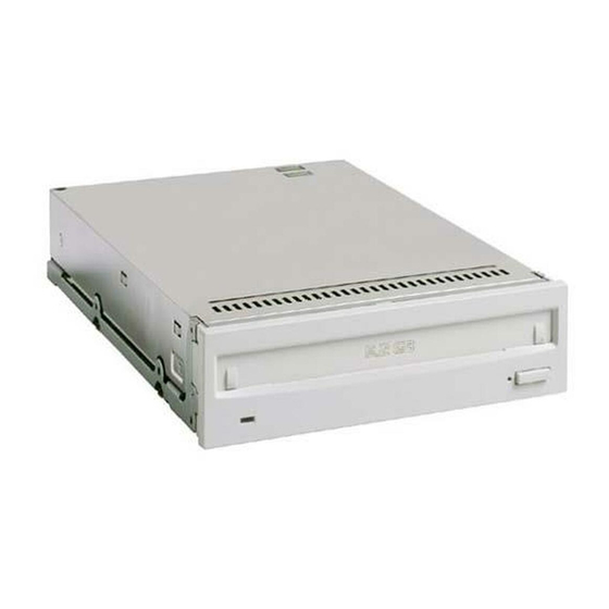
Chapter 1. INTRODUCTION Product Brief The Sony SMO-F551 is a 5.2 Gbytes 5 1/4 inch (130mm) multi-function optical disk drive in a half height form factor. It is compatible with ISO standard 5.2 Gbytes optical disk cartridge. The drive also maintains backward compatibility with ISO 2.6 Gbytes, 1.3 Gbytes and 650 Mbytes cartridges. -
Page 11: Compatible Media
5.07 MB/s with 5.2 Gbytes media. The drive is attached to the host computer through its single ended SCSI-2 interface. Compatible Media SMO-F551 is compatible with the following 5 1/4 inch (130 mm) Magneto Optical Disks. Compatibility Type... -
Page 12: System Configuration
System Configuration SMO-F551 is connected to a host computer through its SCSI interface. The maximum of seven peripheral devices can be linked as a daisy chain on the SCSI bus. Host Computer SCSI Cable SMO-F551 SCSI peripheral devices Fig. 1.2 : System Configuration Example Location and Function of Parts This section provides a general description of the SMO-F551 Magneto-Optical disk drive. -
Page 13: Rear Panel
Fig. 1.4 : Rear View n Functional Switch A 24 pin header socket jumper block is used for setting the SCSI ID and other drive configurations. Refer to section "Functional Switch Settings" for more information. SMO-F551 Technical Guide and Specifications Sony Corporation 1998... -
Page 14: Top Panel
1 2 3 4 5 6 7 8 Optional Switch Fig. 1.5 : Top view n Optional Switches (S501, S502) These two dip switches allow the user to set drive configuration. Refer to Chapter 2., "Optional Switch Setting" section. SMO-F551 Technical Guide and Specifications Sony Corporation 1998... -
Page 15: Chapter 2. Installation
Chapter 2. INSTALLATION Before setting up the SMO-F551 Magneto-Optical disk drive, be sure to check that all required components and accessories are present. Component and Accessory Check List Upon opening the carton, check that all the following items are provided: •... -
Page 16: Cooling Requirements
BUSY indicator LED of the drive will flash at 2 second intervals. The drive sets the Temperature Alarm sense data (Sense key: 4H, ASC/ASCQ: 40H/84H) and returns a CHECK CONDITION status. SMO-F551 Technical Guide and Specifications Sony Corporation 1998... -
Page 17: Functional Switch Settings
Fig. 2.2 : Functional Switch Usage There is no jumper pin placed as factory default. Caution: "Disable Write Cache" and "Disable Auto Spin-up" settings work as an "OR" function with the optional dip switch settings. SMO-F551 Technical Guide and Specifications Sony Corporation 1998... - Page 18 A3/B3 * This pin is NOT directly connected to the GND. Do not use this pin as GND. SMO-F551 drives the signal to GND level depending on the functional switch setting. Otherwise, the signal is not driven to GND level.
- Page 19 Write and Verify operation whenever the drive executes WRITE command. Disable Manual Eject Shorting the pair of pins A8/B8, disables the eject button operation. (i.e. the medium cannot be manually unloaded.) SMO-F551 Technical Guide and Specifications Sony Corporation 1998...
- Page 20 0.20 ns maximum per meter DC resistance: 0.230ƒ¶ maximum per meter at 20 °C It is also recommended that the cumulative cable length should be minimized and the SCSI bus termination should be well maintained. SMO-F551 Technical Guide and Specifications Sony Corporation 1998...
-
Page 21: Scsi And Dc Power Connector
SCSI Connector DC Power Connector Fig. 2.3 : SCSI and DC Power Connector Table 2.3 : DC Power Connector Pin Assignments Pin Number Description DC +12V +12V Return +5V Return DC +5V SMO-F551 Technical Guide and Specifications Sony Corporation 1998... -
Page 22: Scsi Terminator
The bar "•P" above the signal indicates active low. SCSI Terminator SMO-F551 features an internal SCSI bus terminator. When the drive is connected at the end of the SCSI chain, functional switch #11 (Enable Terminator) may be used to terminated the SCSI connection. -
Page 23: Optional Switch Setting
Optional Switch Setting SMO-F551 features Optional Switch S501 and S502. These two optional dip switches allow the user to set the drive configurations. Rear End of the Drive S501 1 2 3 4 5 6 7 S502 1 2 3 4 5 6 7 Optional Switch Fig. - Page 24 Write Cache for Write and Verify command will be valid. Write and Verify Command Enable Fast SCSI Fast SCSI Mode will be set. Reserved: Reserved switches are only for internal use. Do not turn any of the reserved switched ON. SMO-F551 Technical Guide and Specifications Sony Corporation 1998...
-
Page 25: Chapter 3. Precautions
DATA PROTECT Fig. 7.1: Write Protection Tab SMO-F551 Technical Guide and Specifications Sony Corporation 1998... -
Page 26: Notes On Cleaning
Therefore, there is no need to clean the optical lens of the drive. Using a lens cleaning device, such as Sony's Cleaning Cartridge (model number: *MOA-L55/2) may damage the drive. -
Page 27: Chapter 4. Specifications
This section provides the complete information of the SMO-F551. Media Related Characteristics The SMO-F551 has read/write compatibility with ISO standard 5.2 Gbytes (8X Capacity) and 2.6 Gbytes (4X Capacity) media. The drive is also read compatible with 1.3 Gbytes (2X Capacity) and 650 Mbytes (1X Capacity) media. - Page 28 1,149.4 Mbytes User Data Transfer Rate Outer Diameter 4.06 Mbytes/s (max.) 3.56 Mbytes/s (max.) Inner Diameter 2.03 Mbytes/s (max.) 1.78 Mbytes/s (max.) Number of Spare Blocks 4,095 sectors (max.) 4,095 sectors (max.) SMO-F551 Technical Guide and Specifications Sony Corporation 1998...
- Page 29 595.6 Mbytes User Data Transfer Rate Outer Diameter 2.40 Mbytes/s (max.) 2.16 Mbytes/s (max.) Inner Diameter 1.24 Mbytes/s (max.) 1.13 Mbytes/s (max.) Number of Spare Blocks 2,057 sectors (max.) 2,077 sectors (max.) SMO-F551 Technical Guide and Specifications Sony Corporation 1998...
- Page 30 Track 18,750 Sector 30 Capacity per Disk 644.2 Mbytes 590.8 Mbytes per Side 322.1 Mbytes 295.4 Mbytes User Data Transfer Rate 1.04 Mbytes/s (max.) 0.95 Mbytes/s (max.) Spare Block 2,048 sectors (max.) 2,048 sectors (max.) SMO-F551 Technical Guide and Specifications Sony Corporation 1998...
-
Page 31: Drive Specifications
1,024 byte/sector 80 bytes (maximum) 512 byte/sector 40 bytes (maximum) Table 4.7 : Laser Diode Item Specification Laser Diode Type Semiconductor Laser (GaAlInP) Wavelength 685 +/-10 nm Output Power 30 mW (maximum) SMO-F551 Technical Guide and Specifications Sony Corporation 1998... - Page 32 Power Supply Delay Less than 0.5 s at 90% of the final value for both power on and off. (Sequencing) Refer to below chart. Š0.5 sec Š0.5 sec Š0.5 sec Š0.5 sec SMO-F551 Technical Guide and Specifications Sony Corporation 1998...
- Page 33 -305 to 12,192 m (-1,000 to 40,000 ft.) Acoustic Noise 45 dB(A) maximum Measured with a microphone located 1 meter from the front of the drive. Except Loading/Unloading. Mounting Orientation Horizontal or Vertical Tilt < +/-10° SMO-F551 Technical Guide and Specifications Sony Corporation 1998...
- Page 34 CUL CSA C22.2 No. 950, Canada DHHS Laser Compliance 21 CFR Subchapter J, USA TÜV Certification according to EN 60 950, Europe TÜV Certification according to EN 60 825, Europe EN55022 Class B IEC801-2, IEC801-3 SMO-F551 Technical Guide and Specifications Sony Corporation 1998...
-
Page 35: Chapter 5. System Configuration
Chapter 5. SYSTEM CONFIGURATION SMO-F551 consists of mechanical, electrical and optical subsystems. The electrical subsystem consists of analog and digital circuitry. The analog circuitry includes the laser diode driver, RF circuit and servo systems for focusing and tracking. The digital circuitry includes analog and mechanical control logic, modulator/ demodulator, drive interface logic and SCSI control block. -
Page 36: Microprocessor
(Trk) Power Line (LM) Controller and Servo Block Fig. 5.1: SMO-F551 Block Diagram Microprocessor The microprocessor unit (MPU) has 512 kbytes(External) and 64 kbytes(Internal) programmed ROM and 64 kbytes of working RAM on the MPU bus. This module performs the following functions: •... -
Page 37: Dsp/Servo Blocks
DSP/Servo Blocks The SMO-F551 contains the following four servo blocks: Spindle Servo The spindle servo block rotates the disk at 3,000 min (rpm) or 3,600 min (rpm) using a phase-locked-loop servo system which uses the Frequency Generator (FG) signal. Focus Servo The focus servo block controls the two axis actuator to focus the laser diode beam on the disk's surface by the beam-spot-size method. -
Page 38: Buffer Memory
ID data of the disk. The SYNC and RESYNC in the format are encoded and detected in this module. Buffer Memory Buffer Memory is composed of 4 Mbytes of DRAM. User data is stored in reading or writing data upon request. SMO-F551 Technical Guide and Specifications Sony Corporation 1998... -
Page 39: Chapter 6. Host Interface
Chapter 6. HOST INTERFACE For connection with a host system, SMO-F551 uses the SCSI-2 (Small Computer System Interface) which complies with specifications of ANSI X3.131-1994. In this section, a summary of the drive's SCSI specification is described. Refer to the SMO-F551 SCSI Specifications for more details. - Page 40 A signal driven by the initiator to indicate an acknowledgment for an REQ/ACK data transfer handshake. Attention (ATN) A signal driven by the initiator to indicate the ATTENTION condition. Reset (RST) An "OR-tied" signal that indicates the RESET condition. SMO-F551 Technical Guide and Specifications Sony Corporation 1998...
- Page 41 SCSI bus, refer to the ANSI X3.131-1994 (SCSI-2) documents. Single-ended drivers have been adopted for the bus drive. Use a device which satisfies the standards for the driving and receiving circuits. SMO-F551 Technical Guide and Specifications Sony Corporation 1998...
-
Page 42: Control Method And Procedures
Bus Free Phase Linked Not disconnected Arbitration Phase Reselection Phase Message-In Phase Data-In Phase Status Phase Message-In Phase Not linked Bus Free Phase Fig. 6.2: Drive Control Flow Chart through SCSI SMO-F551 Technical Guide and Specifications Sony Corporation 1998... -
Page 43: Command Summary
Command Summary The SMO-F551 supports the following SCSI commands. Refer to the SMO-F551 SCSI Specifications for more information. Code Name Description TEST UNIT READY Provide a means to check whether the logical unit is ready. The function of this command is exactly as same as the REZERO UNIT TEST UNIT READY command. - Page 44 READ DEFECT DATA (10) Scans the medium of written or blank logical blocks. MEDIUM SCAN WRITE BUFFER Write data to the data buffer of the SMO-F551. READ BUFFER Read data from the data buffer of the SMO-F551. READ LONG Read the specified number of data blocks including data bytes and ECC bytes.
-
Page 45: Chapter 7. Busy Indicator
Chapter 7. BUSY INDICATOR The SMO-F551 supports the BUSY indicator notification. The following table shows the flashing pattern of the LED and their means. Flashing Pattern and Drives Internal Condition LED Flashing Pattern BUSY (amber) READY (green) Lights ON - accessing disk... - Page 46 SMO-F551 Magneto-Optical Disk Drive Technical Guide and Specifications...