
Related Manuals for Sony RCP-1001


Summary of Contents for Sony RCP-1001
- Page 1 REMOTE CONTROL PANEL RCP-1000 RCP-1001 OPERATION MANUAL [English] 1st Edition (Revised 3)
-
Page 2: Table Of Contents
Table of Contents Precautions Precautions..............2 Note on interference Do not place mobile phones or similar devices on the control Overview ..............3 panel. Doing so may result in malfunction of the unit. Features ................3 Examples of System Configurations ....... 4 Supported devices ............ -
Page 3: Overview
Up to six units can be mounted in a 19-inch EIA rack. Customizable functions • The RCP-1001 is a compact control panel with specialized Various settings can be configured according to the operation basic operations. The iris and master black adjustment block configuration and the frequency with which functions are used. -
Page 4: Examples Of System Configurations
Examples of System Configurations Connection example for LEGACY mode Camera heads CCU (1 to 6) VCS-700 CNU-700 RCP (1 to 6) MSU-1000/1500 CCU/CNU REMOTE RCP-1000/1001 CCA-5 cable • The maximum cable length for from a CCU (camera control unit) to an RCP is 200 m. •... - Page 5 Connection example for MCS mode Camera heads RCP-1000 MSU-1000/1500 RCP-1001 CCA-5 cable LAN straight cable (category 5 or above) • In MCS mode, be sure to set one of the multiple MSUs as the master. Not to turn off the power or disconnect the cable of the master MSU during operation.
-
Page 6: Supported Devices
Supported devices Operating Cameras This unit supports connection to the following devices. Camera control permissions (panel active, • BVP-E30 series IRIS/MB active, and PARA) • CCU-590/790 series By combining an MSU and RCP, you can operate one camera • HDC-1000(R)/1500(R)/3300(R) series device from multiple control panels, and multiple cameras from •... -
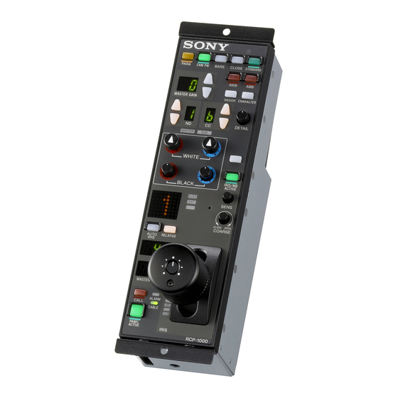
Page 7: Names And Functions Of Parts
Names and Functions of Parts Operation Panel RCP-1000 RCP-1001 Camera/panel control block Camera/panel control block (page 8) (page 8) Function control block Function control block (page 9) (page 9) Adjustment block (page 10) Adjustment block (page 10) Panel control/status display... - Page 8 Camera/panel control block a PARA (parallel control) button f AWB (auto white balance) button This is the PARA function button. It allows you to This button is for starting auto white balance adjustment. The simultaneously control the control panels that are active. button is lit while this function is running and goes out when However, IRIS and master black are only enabled on control adjustment is finished.
- Page 9 Function control block a ND filter selection buttons These buttons are lit when the RCP has the filter servo control permission. When they are not lit, the camera side has the control permission. Pressing either the top or bottom button once switches the control permission to the RCP.
- Page 10 Adjustment block RCP-1000 RCP-1001 1 White balance/black balance adjustment block 2 Iris/master control black adjustment block RCP-1000 a WHITE (manual white balance) knobs These knobs allow you to adjust the R and B signals in order from left to right.
- Page 11 MASTER BLACK knob (RCP-1001 only) c AUTO IRIS button This knob is for manually adjusting the master black. The This button is for adjusting the iris automatically.
-
Page 12: Connector Panel
Panel control/status display block RCP-1000 RCP-1001 a CALL button During fiber cable connections This button is for communication. If it is pressed, the tally state Indicates the communication state of the camera head and for the camera or CCU changes, and a call signal is sent. -
Page 13: Settings
Setting Display Characters to Light-up Settings in Dark Locations Using the EL backlight, a slight light can be emitted from the characters on the panel. This setting makes the characters Setting the Control Panel easy to see in dark surroundings. The selectors shown in the left side of the diagram below is Turn the setting item selector in the control panel until used to set the control panel. -
Page 14: Adjusting The Click Sound Level Of The Buttons
Adjusting the Click Sound Level of the Setting Functions to Assign to the Buttons DETAIL Knob You can adjust the volume of click sound emitted when You can assign either HD Detail or SD Detail to the DETAIL pressing the panel buttons. knob on the control panel. -
Page 15: Assigning Functions To The Assignable Button
Assigning Functions to the Assignable Specifications Button You can assign functions to the assignable button on the control panel. General Power supply 10.5 V to 30 V DC Turn the assignable button selector and set the number of the function to assign to the assignable Power consumption button. - Page 16 Design and specifications are subject to change without notice. Note Always verify that the unit is operating properly before use. SONY WILL NOT BE LIABLE FOR DAMAGES OF ANY KIND INCLUDING, BUT NOT LIMITED TO, COMPENSATION OR REIMBURSEMENT ON ACCOUNT OF THE LOSS OF PRESENT OR PROSPECTIVE...
- Page 17 The material contained in this manual consists of information that is the property of Sony Corporation and is intended solely for use by the purchasers of the equipment described in this manual. Sony Corporation expressly prohibits the duplication of any...
- Page 18 Sony Corporation RCP-1000 (SY) RCP-1001 (SY) 4-169-283-04(1) © 2010...