
Related Manuals for Sony CCP-9000-C


Summary of Contents for Sony CCP-9000-C
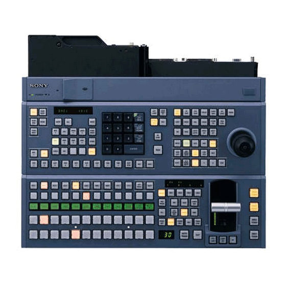
- Page 1 CENTER CONTROL PANEL PACK CCP-9000-C 1 M/E CONTROL PANEL MKS-9011 2 M/E CONTROL PANEL MKS-9012 MKS-8011 MKS-8031TB MKS-8032 MKS-8033 MKS-8035 MKS-8041 MKS-8075 OPERATION MANUAL [English] 1st Edition (Revised 1)
- Page 2 WARNING WARNING: THIS WARNING IS APPLICABLE FOR USA ONLY. To prevent fire or shock hazard, do not expose the unit to rain or moisture. If used in USA, use the UL LISTED power cord specified below. DO NOT USE ANY OTHER POWER CORD. To avoid electrical shock, do not open the cabinet.
- Page 3 WARNUNG Für Kunden in Europa (nur MKS-9011/9012) Dieses Produkt besitzt die CE-Kennzeichnung und erfüllt Dieses Gerät hat keinen Netzschalter. sowohl die EMV-Direktive (89/336/EEC) als auch die Direktive Beim Einbau des Geräts ist daher im Festkabel ein leicht Niederspannung (73/23/EEC) der EG-Kommission. zugänglicher Unterbrecher einzufügen, oder das Netzkabel Die Erfüllung dieser Direktiven bedeutet Konformität für die muß...
- Page 4 Periodic inspections To guarantee safe long-term operation, periodic inspections are recommended. Please contact your Sony representative for detailed information about the content and cost of periodic inspections. Voor de Klanten in Nederland (alleen voor de MKS-9011/...
-
Page 5: Table Of Contents
Table of Contents Overview ................6 Features..................6 Units and Modules ..............6 Optional Accessories ..............7 Location and Function of Parts........... 8 MKS-9011/9012 Front Panel............ 8 MKS-9011/9012 Rear Panel............. 9 MKS-8011 Menu Panel ............11 MKS-8075 Extension Adaptor ..........11 Example System Configuration ........ -
Page 6: Overview
Powerful external device control Overview The center control panel can control devices such as Sony routing switchers and IF processors. Control of devices such as VTRs and DDRs can be linked to timelines of switchers and DME. Overview The CCP-9000 Center Control Panel Pack... -
Page 7: Optional Accessories
Optional Accessories SWC-5002 50-pin Panel Cable (2 m/7 ft) SWC-5005 50-pin Panel Cable (5 m/16 ft) SWC-5010 50-pin Panel Cable (10 m/33 ft) Overview... -
Page 8: Location And Function Of Parts
If the status indicators do not light even though the AC power cord is connected, there may be failure in the unit. Disconnect the AC power cord and contact a Sony service or marketing representative. Location and Function of Parts... -
Page 9: Mks-9011/9012 Rear Panel
MKS-9011/9012 Rear Panel 3 - AC IN A and B connectors 1MENU PANEL connector 2EXT PANEL connector EXT DISPLAY DATA MENU PANEL EXT PANEL EDITOR PANEL REF IN REMOTE CTRL PERIPH qaDATA connector 4GPI connector 5U terminal qsEXT DISPLAY connector 6PERIPH connector 7CTRL connector 8REMOTE connector... - Page 10 (key frame effects, snapshots, etc.) and still * For information about Ethernet switches that can be used in an MVS pictures of frame memory. system, contact your Sony service representative. * Ethernet is a trademark of XEROX Corporation. Caution...
-
Page 11: Mks-8011 Menu Panel
MKS-8011 Menu Panel SCU connector SCU connector (D-sub 50-pin, special interface) Connect to the MENU PANEL connector of the MKS- 8010/9011/9012 System Control Unit. MKS-8075 Extension Adaptor 1SCU IN connector 2SCU OUT connector a SCU IN (system control unit input) connector (D-sub 50-pin, special interface) Connect to one of the EXT PANEL connector of the MKS- 8010/9011/9012 System Control Unit or to the SCU OUT... -
Page 12: Example System Configuration
Example System Configuration MVS-8000 System Configuration MVE-8000 DME Processor Pack Reference video signal Ethernet switch Ethernet switch DATA LAN CTRL BVE-9100 Editing Control System Reference video signal CTRL DATA CTRL REMOTE 1 MKS-9011/9012 System Control Unit DATA REMOTE PERIPH Reference video signal BKS-R Series HDS-X Series MVS-8000SF Switcher Processor Pack... -
Page 13: Center Control Panel Connection
Max. modules the cables supplied in the package, or SWC-5002/5005/ MKS-8031TB Track Ball Module 5010 cables. MKS-8033 Utility/Shotbox Module MKS-8035 Key Control Module MKS-8032 DSK Fader Module Contact your Sony service representative for more information about connectable devices. Example System Configuration... -
Page 14: Exchanging Button Labels
Exchanging Button Adjusting Fader Torque Labels You can adjust faders without removing them from the center control panel or operation modules. A button top puller is supplied with the center control Proceed as follows to adjust faders. panel. After changing a pattern assigned to a numeric button, you can use the following procedure to exchange the button label. -
Page 15: Power Supply Unit Status Indicators
Power Supply Unit Status Maintenance Indicators Clean the menu display screen (touch screen) with a soft cloth lightly moistened with ethanol. The power supply unit status indicators show the status of Be sure to wipe only the dirty places lightly, taking care the power supply unit during operation and when the unit not to spread the dirt. -
Page 16: Specifications
Operating humidity Specifications 10% to 90% Dimensions (w/h/d) 478×208×442 mm (18 ×8 ×17 inches) The following specifications show the reference Mass Approx. 11.5 kg (25 lb 5 oz) performance for this unit and individual option boards/ PC card slot Type II×1 (Supports CardBus) modules. -
Page 17: Mks-9012 2 M/E Control Panel
AC power cord (for Europe only) (250 V 10 A 2.4 m (8 ft)) Data transfer rate: 312/1250 Kbps (Part No.: 1-782-929-21) D-sub 25-pin, female TTL inputs: 8 Relay contact outputs: 4 (30 V AC/DC, MKS-9012 2 M/E Control Panel 0.1 A) Open collector outputs: 4 EDITOR PANEL... -
Page 18: Mks-8031Tb Track Ball Module
MKS-8031TB Track Ball Module MKS-8041 Blank Panel (1/2) Power requirements Power requirements 12 V DC 12 V DC Power consumption Power consumption Max. 1 A Max. 0.1 A Dimensions (w/d, excluding projections) Dimensions (w/d, excluding projections) 220×132 mm (8 ×5 inches) 220×132 mm (8 ×5... - Page 19 The material contained in this manual consists of information that is the property of Sony Corporation and is intended solely for use by the purchasers of the equipment described in this manual. Sony Corporation expressly prohibits the duplication of any...
- Page 20 Sony Corporation B & P Company CCP-9000-C Printed in Japan (WW) 2003.01.13 3-704-635-02 (1) © 2002 Printed on recycled paper...