Yaesu FT3DR Operating Manual
C4fm/fm 144/430mhz digital/analog transceiver
Hide thumbs
Also See for FT3DR:
- Operating manual (98 pages) ,
- Instruction manual (63 pages) ,
- Technical supplement (53 pages)
Table of Contents
Advertisement
Quick Links
Advertisement
Table of Contents

Related Manuals for Yaesu FT3DR


Summary of Contents for Yaesu FT3DR
- Page 1 C4FM/FM 144/430MHz DIGITAL/ANALOG TRANSCEIVER FT3DR Operating Manual...
-
Page 2: Table Of Contents
Contents Quick Guide ............ 3 Split Memory ..............26 Using Memory Tag ............26 Controls & Connections ........ 4 Using Memory Bank ............26 Transceiver ...............4 Touch Screen Display .............6 Scanning Function ........27 VFO Scan ...............27 Supplied Accessories and Options ....9 Memory Channel Scanning ..........27 Supplied Accessories ............9 Programmable Memory scan (PMS) ......28... -
Page 3: Quick Guide
Quick Guide ① Turning the Power ON ⑤ Adjusting the volume Install the charged battery pack and then Rotate the VOL knob to adjust the volume press and hold the switch. to a comfortable level. ② Inputting the Call sign ⑥... -
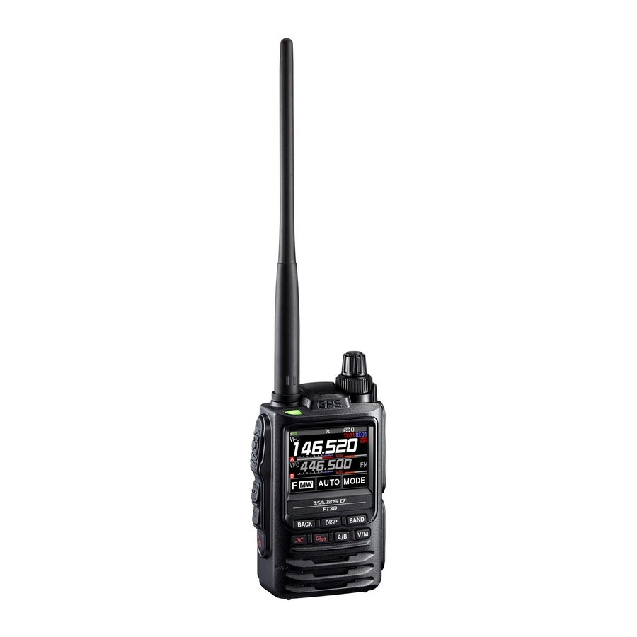
Page 4: Controls & Connections
Controls & Connections Transceiver ① ⑩ ② ③ ⑧ ④ ⑭ ⑪ ⑮ ⑤ ⑥ ⑫ ⑯ ⑰ ⑦ ⑧ ⑬ ⑨ ① ⑪ GPS Antenna Full Color Touch screen display Touch to set the frequency and various ② Antenna Jack (SMA)* other settings. - Page 5 SD card slot and EXT DC IN jack are securely covered with rubber caps, the ⑮ DATA Terminal* FT3DR meets the waterproofing performance When updating the firmware, connect to a PC conforming to IPX5. using a USB cable.
-
Page 6: Touch Screen Display
Touch Screen Display Lights when Auto Power Off is active Lights when DTMF function is enabled Lights when AF DUAL Function is enabled Lights when GPS is acquired Lights when the mute unction is active Lights when GPS Log Function is enabled LOCK Lights when a microSD memory card is inserted Battery condition... - Page 7 ● Dual Band Screen A-band and B-band are displayed in a top-down fashion. ● Function Menu Screen Touching [F MW] displays the function menu screen. Function Menu Screen 1 Function Menu Screen 2 ● GPS Screen ● Band Scope Screen The GPS satellite statuses are shown The screen appears as shown, when the with number.
- Page 8 About Waterproofing Feature Conforming to IPX5 When the included antenna and battery pack are installed and the MIC/SP jack, EXT DC IN jack, DATA terminal, and micro SD slot are securely covered with rubber caps, this product is moisture and splash resistant. To ensure continued waterproofing pro- tection, be sure to check the following points before use.
-
Page 9: Supplied Accessories And Options
Supplied Accessories and Options Supplied Accessories Rechargeable Li-Ion Battery Pack (7.2 V, 2,200 mAh) SBR-14LI Battery Charger SAD-25B Antenna Belt Clip USB Cable Operating Manual (This Manual) SBR-14LI Manual Battery Pack protective cap If any item is missing, contact the dealer from which you purchased the transceiver. Available Options Speaker / Microphone MH-34B4B... -
Page 10: Preparation
Preparation Installing the Antenna 1. Turn the antenna clockwise until it is secured. Do not hold or twist the upper part of the antenna Hold the thick base when installing or removing it. To do so may break the of the antenna conductors inside the antenna. -
Page 11: Charging The Battery Pack
Charging the Battery Pack Charging the Battery Pack using the Battery Charger (SAD-25B) Using the supplied battery charger (SAD-25B), it takes about 9 hours* to charge the SBR-14LI battery pack fully. *Depending on the battery status, the charging time might be increased 1. -
Page 12: External Power Supply
External Power Supply Connecting an External Power Supply for Use in Vehicle The optional DC Cable with Cigarette-Lighter plug (SDD-13) allows power to be supplied from a motor vehicle type cigarette lighter socket. Connecting to an External Power Supply Using a Power Cable The optional DC cable (E-DC-6) allows the transceiver to be connected to an external DC power supply. -
Page 13: Operation
Operation Turning the Transceiver ON 1. Press and hold the Power (Lock) switch to turn the transceiver ON. ● Inputting the call sign The first time the transceiver is turned ON after it is purchased; input your own call sign. 1. -
Page 14: Toggling The Operating Band
Toggling the Operating Band Normally, both operating bands are displayed on the top half and bottom half of the transceiver touch screen. This is Dual band. With one of the bands selected, change the frequency and radio operating mode. • The selected band (displayed in white letters) is called Operating band. -
Page 15: Changing The Frequency Step
● The numeric keys 1. Touch the frequency displayed on the LCD. The numeric keypad appears. 2. Enter the frequency using the numeric keys. Example: To input 145.520 MHz [1] [4] [5] [5] [2] Example: To input 430.000 MHz [4] [3] [ENT] When entering a frequency using the numeric keys, it may be canceled by pressing the PTT switch or the [BACK] key. -
Page 16: Selecting The Communication Mode
Selecting the Communication Mode ● Using AMS The FT3DR transceiver is equipped with the AMS (Auto- matic Mode Select) function which automatically selects the communication mode corresponding to the received signal. To utilize the AMS function, touch [MODE] to display “... -
Page 17: Fixing The Communication Mode
Fixing the Communication Mode 1. To fix the transmission mode for operation, touch [MODE] to switch the communication mode. Communication Mode Icon Description of Modes This is the standard digital mode. V/D Mode (Voice/Data simultaneous trans- Calls are less prone to interruptions caused by detec- mission mode) tion and correction of the received digital voice signal. -
Page 18: Changing The Transmission Power Level
Changing the Transmission Power Level 1. Touch [F MW], then touch [TX PWR]. 2. Rotate the DIAL knob to select one of the following transmission power levels. TX PO Level PO Meter HIGH (5 W)* LOW3 (2.5 W) LOW2 (1 W) LOW1 (0.1 W) *The default setting. -
Page 19: Using The Convenient Digital C4Fm Feature
2. When accessing the C4FM digital repeater controlled by the DG-ID number, set the transmit DG-ID number of the FT3DR to that of the repeater input. Even in that case, if the receive DG-ID number of the FT3DR is set to “00”, all the downlink signals from the repeater may be received. - Page 20 2. Press the [GM] key again to select the receive DG-ID (DG-ID RX). If the receive DG-ID number is not set “00”, press the [GM] key then rotate the DIAL knob to set “00”. 3. Press and hold the [GM] key, or press the PTT switch to save the setting and return to the normal operation.
- Page 21 3. Press the [GM] key again, then rotate the DIAL knob to select the receive DG-ID (DG-ID RX). 4. Press the [GM] key, then rotate the DIAL knob to set the receive DG-ID (DG-ID RX) to “50”. 5. Press and hold the [GM] key, or press the PTT switch to save the setting and return to the normal operation.
- Page 22 Setting the receive DG-ID number to “00” , all the C4FM digital stations may The group member set the DG-ID number to “50” be received signals. DG-ID DG-ID DG-ID DG-ID (transmit) (transmit) (transmit) (transmit) (receive) (receive) (receive) (receive) Only group members set to the same DG-ID number may communicate.
-
Page 23: Repeater Operation
Repeater Operation Communicating Via the Repeater The transceiver includes an ARS (Automatic Repeater Shift) function which sets the re- peater operation automatically when the receiver is tuned to the repeater frequency. 1. Set the downlink (output) frequency from the repeater. Repeater Shift Icon 2. -
Page 24: Using The Memory
The transceiver may be placed into a Memory Channel Only mode, (which restricts the FT3DR to operate only on the memory channels), by pressing the [V/M] key, while pressing the Power (Lock) switch to turn the transceiver ON. To cancel the Memory Channel Only mode, turn the transceiver OFF, then press the [V/M] key again, while pressing Power (Lock) switch to turn the transceiver ON. -
Page 25: Clearing Memories
Clearing Memories 1. Touch and hold [F MW]. 2. Rotate the DIAL knob to select the memory channel from which the data is to be cleared. 3. Touch [ ], then touch [M.DEL]. Confirmation screen “DELETE?” is displayed. 4. Touch [OK] twice to clear the memory channel. Data on memory channel One, and the Home channel may not be cleared. -
Page 26: Split Memory
Split Memory Two different frequencies, one for receive and another for transmit, can be registered to a memory channel. Using Memory Tag Memory name tags may be assigned to the memory channels and home channels. Using Memory Bank The transceiver allows using up to 24 memory banks to allow sorting and registering the channels in convenient groups. -
Page 27: Scanning Function
• Memory Bank Scan For additional details on the Programmable Memory Scan (PMS) and Memory Bank Scan, refer to the Advanced Manual which may be downloaded from the Yaesu website. VFO Scan VFO scan function scans the frequencies, and detects signals. -
Page 28: Programmable Memory Scan (Pms)
Programmable Memory scan (PMS) This function scans only the range of frequencies between the lower and upper limits registered in a pair of PMS Programmable Memory channels. 50 sets of PMS memory channels (L1/U1 to L50/U50) are available. Dual Receive (DW) feature The transceiver checks for signals on the frequency registered to the selected memory channel (Priority Memory Channel) once approximately every 5 seconds. -
Page 29: Convenient Functions
● About communicable range The communicable distance between SSM-BT10 and FT3DR is about 10m, but it chang- es greatly depending on the surrounding conditions and the human body. When connecting to a Bluetooth Headset for the first time -Pairing- When using the Bluetooth Headset for the first time, the Bluetooth Headset and the FT3DR must be paired. -
Page 30: Hands-Free Operation With A Bluetooth Headset (Vox Function)
When the VOX function is OFF, pressing the “Call button”* on the Bluetooth headset once will keep the FT3DR in transmission and you can make a call using the Bluetooth headset. If you press the “Call button”* again, FT3DR will return to the reception state. -
Page 31: Vox Operation
VOX Operation The VOX system provides automatic transmit/receive switching based on voice input to the microphone or Bluetooth Headset. With the VOX system enabled, you do not need to press the PTT switch in order to transmit, and it is not necessary to use a VOX head- set in order to utilize VOX operation. -
Page 32: Band Scope
Band Scope The Spectrum Analyzer presents a view of operating activity on channels above and be- low the current main band operating frequency as the center. 1. Touch [F MW]. 2. Touch [ ], and then touch [SCOPE]. 3. With the current frequency in the center, the signal strengths of 39 channels bandwidth are shown on a graph. -
Page 33: Gps Function
GPS Function FT3DR is equipped with GPS (Global Positioning System) reception function. When receiving signals from GPS satellites, the current position (latitude, longitude, alti- tude) can be calculated and displayed within the tolerance of several meters. In addition, GPS can receive the exact time from a satellite-mounted atomic clock. -
Page 34: Using Set Mode
Using Set Mode The Set Mode permits configuring the various functions according to individual operating needs and preferences. Set Mode Operation 1. Press and hold the [DISP] key. The SET MODE screen will be displayed. 2. Touch the desired item in Set Mode. The Sub-menu screen will be displayed. -
Page 35: Tables Of Set Mode Operations
Tables of Set Mode Operations Selectable options Set mode no. / item Description (Options in bold are the default settings) DISPLAY 1 TARGET LOCATION Set what to display using the smart COMPASS / NUMERIC navigation function. 2 COMPASS Set the compass display of the smart HEADING UP / NORTH UP navigation function. - Page 36 Selectable options Set mode no. / item Description (Options in bold are the default settings) MEMORY 1 BANK LINK Set the memory bank link. BANK1 to BANK24 BANK LINK ON / OFF 2 BANK NAME Assign a name to each memory bank. BANK1 to BANK24 3 MEMORY NAME Input the memory channel tag.
- Page 37 Selectable options Set mode no. / item Description (Options in bold are the default settings) 6 PRIORITY REVERT Turn the “Priority Channel Revert” ON / OFF feature ON or OFF during Dual Receive. * For details of the functions, refer to the GM Function Instruction Manual. 1 DP-ID LIST Displays the DP-ID list screen.
- Page 38 Selectable options Set mode no. / item Description (Options in bold are the default settings) APRS * For details of the functions, refer to the APRS Instruction Manual. 1 APRS AF DUAL Turn ON/OFF the muting function ON / OFF when both the APRS function and AF dual function are active.
- Page 39 Selectable options Set mode no. / item Description (Options in bold are the default settings) 10 APRS RINGER Set the bell ring on/off when a beacon Mic-E : ON / OFF or message is received. POSITION : ON / OFF WEATHER :...
- Page 40 Set your station symbol. 48 icons including 1(/[Human/Person]) / 2(/b Bicycle) / 3(/> Car) / 4(YY Yaesu Radios) 26 POSITION COMMENT Set up the position comment function. Off Duty / En Route / In Service / Returning / Committed / Special / Priority / Custom 0 to 6 / EMERGENCY! STATUS :...
-
Page 41: Restoring To Defaults (Reset)
Restoring to Defaults (Reset) Caution When the All Reset function is performed, all data registered in the memory will be deleted. Be sure to note the settings on paper or back up the data on a microSD memory card. For details on how to save backup onto a microSD memory card. -
Page 42: Specifications
Specifications ● General Frequency Range : TX 144 - 148 MHz, 430 - 450 MHz : RX: A- Band 0.5 MHz - 729 MHz, 800 MHz - 985 MHz (Cellular Blocked) B- Band 108 MHz - 580 MHz Channel Steps : 5/6.25/(8.33)/10/12.5/15/20/25/50/100 kHz ( ) Air Band Mode of Emission... - Page 43 ● Receiver Circuit Type : Double-conversion super heterodyne (FM / AM) Direct-conversion (AM / FM Radio) Intermediate Frequency : 1st: A- Band 58.05 MHz 1st: B- Band 57.15 MHz 2nd: A- Band, B- Band 450 kHz Sensitivity * A- Band only Selectivity (-6 dB/-60 dB) : NFM, AM 12 kHz/35 kHz AF Output...
- Page 44 Changes or modifications to this device that are not expressly approved by YAESU MUSEN could void the user’s authorization to operate this device. This device complies with part 15 of the FCC Rules. Operation is subject to the following two conditions: ( 1 ) This device may not cause harmful interference, and ( 2 ) this device must accept any interference including received, interference that may cause undesired operation.
- Page 45 Brand Name: YAESU Model Number: FT3DR Manufacturer: YAESU MUSEN CO., LTD. Address of Manufacturer: Tennozu Parkside Building, 2-5-8 Higashi-Shinagawa, Shinagawa-ku,Tokyo 140-0002 Japan This device complies with part 15 of the FCC Rules. Operation is subject to the following two conditions; (1) this device may not cause harmful interference, and (2) this device must accept any interference received, including interference that may cause undesired operation.
- Page 46 Copyright 2019 YAESU MUSEN CO., LTD. All rights reserved. No portion of this manual may be reproduced without the permission of YAESU MUSEN CO., LTD. YAESU MUSEN CO., LTD. Tennozu Parkside Building 2-5-8 Higashi-Shinagawa, Shinagawa-ku, Tokyo 140-0002 Japan YAESU USA Printed in Japan 6125 Phyllis Drive, Cypress, CA 90630, U.S.A.