Yaesu FT3DR Technical Supplement
C4fm/fm 144/430mhz dual band digital transceiver
Hide thumbs
Also See for FT3DR:
- Operating manual (98 pages) ,
- Instruction manual (63 pages) ,
- Advanced manual (45 pages)
Advertisement
Quick Links
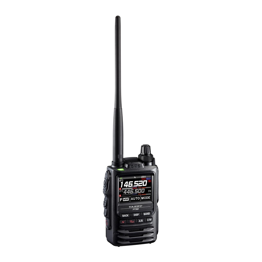
C4FM/FM 144/430 MHz
Dual Band Digital Transceiver
FT3DR/FT3DE
Introduction
This manual provides the technical information necessary for
servicing the FT3DR/FT3DE 144/430 MHz Dual Band Digital
Transceiver.
Servicing this equipment requires expertise in handing surface-
mount chip components. Attempts by non-qualified persons
to service this equipment may result in permanent damage not
covered by the warranty, and may be illegal in some countries.
While we believe the information in this manual to be correct,
YAESU assumes no liability for damage that may occur as a
result of typographical or other errors that may be present. Your
cooperation in pointing out any inconsistencies in the technical
information would be appreciated.
Caution
Risk of explosion if battery is replaced by an incorrect type.
Dispose of used batteries according to the instructions.
Important Note
This transceiver was assembled using Pb (lead) free sol-
der, based on the RoHS specification.
Only lead-free solder (Alloy Composition: Sn-3.0Ag-0.5Cu)
should be used for repairs performed on this apparatus.
The solder stated above utilizes the alloy composition re-
quired for compliance with the lead-free specification, and
any solder with the above alloy composition may be used.
TECHNICAL SUPPLEMENT
Specifications
Exploded View & Miscellaneous Parts
Block Diagram
Alignment
Board Unit (Schematics, Layouts & Parts)
RF Unit
CNTL Unit
CABLE Unit
EH072M90B
©2019 YAESU MUSEN CO., LTD.
Contents
Advertisement

Related Manuals for Yaesu FT3DR


Summary of Contents for Yaesu FT3DR
- Page 1 RF Unit While we believe the information in this manual to be correct, CNTL Unit YAESU assumes no liability for damage that may occur as a CABLE Unit result of typographical or other errors that may be present. Your cooperation in pointing out any inconsistencies in the technical information would be appreciated.
- Page 2 (MID3: 2.5 W/LOW2: 1.0 W/LOW1: 0.3 W) 0.9 W (FBA-39) (LOW1: 0.3 W) Modulation Type: F1D, F2D, F3E : Variable Reactance modulation F7W: 4 FSK (C4FM) Spurious Emission: USA/EXP version At least 60 dB below (@TX Power HI, LOW3) At least 50 dB below (@TX Power LOW2, LOW1) SPECIFICATIONS-1 FT3DR/FT3DE Technical Supplement...
- Page 3 300 mW (8 Ω for 10 % THD 7.4 V) external speaker Bluetooth Version: Version 4.2 Class: Class 2 Output Power: 2 dBm typ Specifications are subject to change without notice, and are guaranteed within the 144/430 MHz amateur bands only. SPECIFICATIONS-2 FT3DR/FT3DE Technical Supplement...
- Page 4 RARA1236700 U9900293 SPECIAL TAPTITE-B 2X3.5B(CAP) O RING (4.8X1.9) ⑧ GPS ASSY SHAFT CABLE-UNIT RA6247900 RA6247200 Non-designated parts are available only as part of a designated assembly. Q7000686 NUT(ANT) MASK SHEET(REAR) GPS MODULE RA6267300 DOUBLE FACE(GPS) EXPLODED VIEW-1 FT3DR/FT3DE Technical Supplement...
- Page 5 Block Diagram BLOCK DIAGRAM-1 FT3DR/FT3DE Technical Supplement...
- Page 6 Alignment Introduction and Precautions Required Test Equipment RF Signal Generator with calibrated output level The FT3DR/FT3DE has been carefully aligned at at 500 MHz the factory for performance across the specified Deviation Meter (linear detector) amateur bands. Realignment should therefore In-line Wattmeter with 5% accuracy at 500 MHz not be necessary except in the event of a compo- ...
- Page 7 6. Press and hold in the [ GM ] key while powering Regulated 9.1 VDC P.S. the transceiver "ON" again. The transceiver will Figure 1: TX Alignment Setup enter the adjustment mode, and the display will show the first alignment setting. Thereaf- ter, the frequencies used during alignment will automatically be set without action by the tech- nician. ALIGNMENT-2 FT3DR/DE Technical Supplement...
- Page 8 Press the [ X ] key two times to store the FM Threshold level S-Meter Full Scale level. Press the [ V/M ] button (the "Data" will disap- Press the [ V/M ] button (the "Data" will disap- pear on the display). pear on the display). ALIGNMENT-3 FT3DR/DE Technical Supplement...
- Page 9 4.2 kHz ± 0.05 kHz (USA version) or 4.5 kHz ± 0.05 kHz (EXP, EU versions). Release the PTT switch, and then press the [ V/M ] button (the "Data" will disappear on the display). ALIGNMENT-4 FT3DR/DE Technical Supplement...
- Page 10 Press the [ V/M ] button (the "Data" will appear on the display). Press the [ X ] key two times to read the Squelch Threshold level. Press the [ V/M ] button (the "Data" will disap- pear on the display). ALIGNMENT-5 FT3DR/DE Technical Supplement...
- Page 11 Press the [ V/M ] button (the "Data" will appear on the display). Press the [ X ] key two times to store the FM S-Meter Full Scale level. Press the [ V/M ] button (the "Data" will disap- pear on the display). ALIGNMENT-6 FT3DR/DE Technical Supplement...
- Page 12 (the "Data" will disappear on the dis- Press the [ X ] key two times to store the FM play). S-Meter Full Scale level. Press the [ V/M ] button (the "Data" will disap- pear on the display). ALIGNMENT-7 FT3DR/DE Technical Supplement...
- Page 13 4.2 kHz ± 0.05 kHz (USA version) or 4.5 kHz ± 0.05 kHz (EXP/EU versions). Release the PTT switch, and then press the [ V/M ] button (the "Data" will disappear on the display). ALIGNMENT-8 FT3DR/DE Technical Supplement...
- Page 14 Press the [ V/M ] button (the "Data" will appear on the display). Press the [ X ] key two times to store the FM S-Meter S-1 level. Press the [ V/M ] button (the "Data" will disap- pear on the display). ALIGNMENT-9 FT3DR/DE Technical Supplement...
- Page 15 Press the [ V/M ] button (the "Data" will appear on the display). Rotate the DIAL knob for maximum deflection on the SINAD meter. Press the [ V/M ] button (the "Data" will disap- pear on the display). ALIGNMENT-10 FT3DR/DE Technical Supplement...
- Page 16 Press the [ V/M ] button (the "Data" will appear on the display). Press the [ X ] key two times to store the FM S-Meter S-1 level. Press the [ V/M ] button (the "Data" will disap- pear on the display). ALIGNMENT-11 FT3DR/DE Technical Supplement...
- Page 17 RF Unit (Lot. 1) Circuit Diagram RF-1 FT3DR/FT3DE Technical Supplement...
- Page 18 RF Unit (Lot. 1) Parts Layout Side A Side B RF-2 FT3DR/FT3DE Technical Supplement...
- Page 19 RF Unit (Lot. 2 - 3) Circuit Diagram RF-3 FT3DR/FT3DE Technical Supplement...
- Page 20 RF Unit (Lot. 2 - 3) Parts Layout Side A Side B RF-4 FT3DR/FT3DE Technical Supplement...
- Page 21 RF Unit (Lot. 4 - ) Circuit Diagram RF-5 FT3DR/FT3DE Technical Supplement...
- Page 22 RF Unit (Lot. 4 - ) Parts Layout Side A Side B RF-6 FT3DR/FT3DE Technical Supplement...
- Page 23 K22178809 C 1078 CHIP CAP. 22pF GRM1552C1H220GA01D K22179707 C 1079 CHIP CAP. 22pF GRM1552C1H220GA01D K22179707 C 1080 CHIP CAP. 0.001uF GRM155B11H102KA01D K22178809 C 1081 CHIP CAP. 0.001uF GRM155B11H102KA01D K22178809 C 1082 CHIP CAP. 0.001uF GRM155B11H102KA01D K22178809 RF-7 FT3DR/FT3DE Technical Supplement...
- Page 24 K22068801 C 1151 CHIP CAP. 0.01uF GRM155B11E103KA01D K22148834 C 1152 CHIP CAP. 6.3V GRM155B30J105KE18D K22088803 C 1153 CHIP CAP. 0.0047uF GRM155B11H472KA01D K22178838 C 1154 CHIP CAP. 4.7uF AMK105BJ475MV-F K22068801 C 1155 CHIP CAP. 0.01uF GRM155B11E103KA01D K22148834 RF-8 FT3DR/FT3DE Technical Supplement...
- Page 25 K22178236 C 1227 CHIP CAP. 100pF GRM1552C1H101JA01D K22178236 C 1229 CHIP CAP. 0.01uF GRM155B11E103KA01D K22148834 C 1230 CHIP CAP. 22pF GRM1552C1H220JA01D K22178220 C 1231 CHIP CAP. 0.01uF GRM155B11E103KA01D K22148834 C 1233 CHIP CAP. 100pF GRM1552C1H101JA01D K22178236 RF-9 FT3DR/FT3DE Technical Supplement...
- Page 26 K22178236 C 1312 CHIP CAP. 15pF GRM1552C1H150JA01D K22178216 C 1313 CHIP CAP. 0.01uF GRM155B11E103KA01D K22148834 C 1314 CHIP CAP. 100pF GRM1552C1H101JA01D K22178236 C 1315 CHIP CAP. 15pF GRM1552C1H150GA01D K22178300 C 1316 CHIP CAP. 15pF GRM1552C1H150JA01D K22178216 RF-10 FT3DR/FT3DE Technical Supplement...
- Page 27 K22179711 C 1398 CHIP CAP. 180pF GRM1552C1H181JA01D K22179711 C 1399 CHIP CAP. 0.001uF GRM155B11H102KA01D K22178809 C 1400 CHIP CAP. 0.001uF GRM155B11H102KA01D K22178809 C 1402 CHIP CAP. 0.001uF GRM155B11H102KA01D K22178809 C 1403 CHIP CAP. 330pF GRM1555C1H331JA01D K22179744 RF-11 FT3DR/FT3DE Technical Supplement...
- Page 28 K22178809 C 1469 CHIP CAP. 0.001uF GRM155B11H102KA01D K22178809 C 1471 CHIP CAP. 4.7uF AMK105BJ475MV-F K22068801 C 1472 CHIP CAP. 4.7uF AMK105BJ475MV-F K22068801 C 1473 CHIP CAP. 0.1uF GRM155B11A104KA01D K22108802 C 1474 CHIP CAP. 0.1uF GRM155B11A104KA01D K22108802 RF-12 FT3DR/FT3DE Technical Supplement...
- Page 29 G2070620 D 1017 DIODE 1SS381.H3F(T G2071552 D 1018 DIODE JDP2S04E(TAPE) G2071180 D 1019 DIODE 1SV281(TPH3.F) G2070620 D 1020 DIODE JDP2S02AFS(TPL3) G2071434 D 1021 DIODE 1SV325(TPH3.F) G2070848 D 1022 DIODE 1SV325(TPH3.F) G2070848 D 1023 DIODE 1SV325(TPH3.F) G2070848 RF-13 FT3DR/FT3DE Technical Supplement...
- Page 30 GRN 25 2/2 T50502500 L 1001 M.RFC 0.01uH C1005C-10NJ-RF L1691347 L 1002 M.RFC 0.018uH C1005C-18NJ-RF L1691363 L 1004 CHIP COIL 0.1uH LQW18ANR10G00D L1690892 L 1005 M.RFC 0.0082uH HK1005 8N2J-T L1691276 L 1006 M.RFC 0.0047uH HK1005 4N7S-T L1691280 RF-14 FT3DR/FT3DE Technical Supplement...
- Page 31 L 1078 COIL 0.0167uH F2304C L0023023 L 1079 COIL 0.0399uH F2308C L0023027 L 1080 COIL 0.0399uH F2308C L0023027 L 1081 COIL 0.0336uH F2307C L0023026 L 1082 M.RFC 0.12uH C1608CB-R12G-RF L1691100 L 1083 COIL 0.022uH F2305C L0023024 RF-15 FT3DR/FT3DE Technical Supplement...
- Page 32 2SC4915-O(TE85L.F) G3349158O Q 1056 TRANSISTOR 2SC4915-O(TE85L.F) G3349158O Q 1057 AK1574 G1095614 Q 1058 TC75S51FU(TE85L.F) G1094194 Q 1059 AK1574 G1095614 Q 1060 TRANSISTOR 2SC4915-O(TE85L.F) G3349158O Q 1061 TRANSISTOR DTC144EM T2L G3070309 Q 1062 TRANSISTOR DTC144EM T2L G3070309 RF-16 FT3DR/FT3DE Technical Supplement...
- Page 33 1/16W RMC1/16S 221JTH J24189017 R 1019 CHIP RES. 1/16W RMC1/16S 473JTH J24189045 R 1020 CHIP RES. 1/16W RMC1/16S 221JTH J24189017 R 1021 CHIP RES. 1/16W RMC1/16S 103JTH J24189037 R 1022 CHIP RES. 1/16W RMC1/16S 473JTH J24189045 RF-17 FT3DR/FT3DE Technical Supplement...
- Page 34 RMC1/16S 225JTH J24189065 R 1097 CHIP RES. 2.2M 1/16W RMC1/16S 225JTH J24189065 R 1098 CHIP RES. 1/16W RMC1/16S 103JTH J24189037 R 1099 CHIP RES. 1/16W RMC1/16S 153JTH J24189039 R 1100 CHIP RES. 150k 1/16W RMC1/16S 154JTH J24189051 RF-18 FT3DR/FT3DE Technical Supplement...
- Page 35 1/16W RMC1/16S 102JTH J24189025 R 1170 CHIP RES. 1/16W RMC1/16S 561JTH J24189022 R 1171 CHIP RES. 1/16W RMC1/16S 151JTH J24189015 R 1172 CHIP RES. 1/16W RMC1/16S 473JTH J24189045 R 1173 CHIP RES. 1/16W RMC1/16S 102JTH J24189025 RF-19 FT3DR/FT3DE Technical Supplement...
- Page 36 R 1248 CHIP RES. 1/16W RMC1/16 000JATP J24185000 VER A2 R 1248 CHIP RES. 1/16W RMC1/16 000JATP J24185000 VER B2 R 1249 CHIP RES. 470k 1/16W RMC1/16S 474JTH J24189057 R 1250 CHIP RES. 1/16W RMC1/16S 101JTH J24189013 RF-20 FT3DR/FT3DE Technical Supplement...
- Page 37 RMC1/16S 184JTH J24189052 R 1333 CHIP RES. 150k 1/16W RMC1/16S 154JTH J24189051 R 1334 CHIP RES. 1/16W RMC1/16S 473JTH J24189045 R 1335 CHIP RES. 1/16W RMC1/16S 683JTH J24189047 R 1336 CHIP RES. 1/16W RMC1/16S 473JTH J24189045 RF-21 FT3DR/FT3DE Technical Supplement...
- Page 38 S 1004 TACT SWITCH SKSLLAE010 N5090184 S 1005 TACT SWITCH SKSLLAE010 N5090184 X 1001 XTAL 32.768kHz DST1610A-32.768KHZ H0103492 X 1001 XTAL 32.768kHz TFX-04-32.768KHZ H0103502 X 1002 VCTCXO 57.6MHz DSA211SDN-57.6MHZ H9501946 X 1003 VCTCXO 44MHz DSA211SDN-44.0MHZ H9501948 RF-22 FT3DR/FT3DE Technical Supplement...
- Page 39 YAESU P/N VERS. LOT SIDE LAY ADR XF1001 XTAL FILTER 58.05MHz 58S15AB-58.05MHZ H1102534 XF1002 XTAL FILTER 57.15MHz 57S15AB-57.15MHZ H1102532 SPONGE RUBBER (091302) RA6270100 SHIELD SHEET (CE) RA6286000 EUROPE SHIELD SHEET (CE) RA6286000 EXPORT SHIELD SHEET (CE) RA6286000 RF-23 FT3DR/FT3DE Technical Supplement...
- Page 40 CNTL Unit (Lot. 1 - 3) Circuit Diagram FT3DR/FT3DE Technical Supplement CNTL-1...
- Page 41 CNTL Unit (Lot. 1 - 3) Parts Layout Side A Side B FT3DR/FT3DE Technical Supplement CNTL-2...
- Page 42 CNTL Unit (Lot. 4 - ) Circuit Diagram FT3DR/FT3DE Technical Supplement CNTL-3...
- Page 43 CNTL Unit (Lot. 4 - ) Parts Layout Side A Side B FT3DR/FT3DE Technical Supplement CNTL-4...
- Page 44 Parts List DESCRIPTION VALUE TOL. MFR'S DESIG YAESU P/N VERS. LOT SIDE LAY ADR Please Contact YAESU when replacing the CNTL-Unit. PCB with Components is included CNTL-1 ASSY (see Exploded View) BT2001 LITHIUM BATT. ML614R-TT31 Q9000895 C 2001 CHIP CAP.
- Page 45 K22068801 C 2153 CHIP CAP. 6.3V GRM155B30J105KE18D K22088803 C 2155 CHIP CAP. 6.3V GRM155B30J105KE18D K22088803 C 2157 CHIP CAP. 6.3V GRM155B30J105KE18D K22088803 C 2158 CHIP CAP. 0.22uF GRM155B31A224KE18D K22108808 C 2159 CHIP CAP. 0.22uF GRM155B31A224KE18D K22108808 CNTL-6 FT3DR/FT3DE Technical Supplement...
- Page 46 L1690843 FB2004 FERRITE BEADS BLM15AG121SN1D L1690843 FB2005 FERRITE BEADS BLM15AG121SN1D L1690843 FB2006 FERRITE BEADS BLM15AG121SN1D L1690843 FB2007 FERRITE BEADS BLM15AG121SN1D L1690843 FB2008 FERRITE BEADS BLM15AG121SN1D L1690843 FB2009 FERRITE BEADS BLM15AG121SN1D L1690843 FB2010 FERRITE BEADS BLM15AG121SN1D L1690843 CNTL-7 FT3DR/FT3DE Technical Supplement...
- Page 47 2SK3541 T2L G3835417 Q 2052 2SK3541 T2L G3835417 Q 2053 TRANSISTOR DTC144EM T2L G3070309 Q 2055 2SK3541 T2L G3835417 Q 2056 2SK3541 T2L G3835417 Q 2057 2SK3541 T2L G3835417 ø Please Contact YAESU when replacing this part. CNTL-8 FT3DR/FT3DE Technical Supplement...
- Page 48 0.5% RR0510R-220-D J24189079 R 2065 CHIP RES. 1/16W 0.5% RR0510R-220-D J24189079 R 2066 CHIP RES. 1.5k 1/16W 0.5% RR0510P-152-D J24189123 R 2067 CHIP RES. 1/16W 0.5% RR0510P-102-D J24189119 R 2068 CHIP RES. 1/16W RMC1/16S JPTH J24189070 CNTL-9 FT3DR/FT3DE Technical Supplement...
- Page 49 J24189049 R 2144 CHIP RES. 100k 1/16W RMC1/16S 104JTH J24189049 R 2145 CHIP RES. 1/16W 0.5% RR0510P-913-D J24189594 R 2146 CHIP RES. 270k 1/16W 0.5% MCR01MZPD2703 J24189329 R 2147 CHIP RES. 4.7k 1/16W RMC1/16S 472JTH J24189033 CNTL-10 FT3DR/FT3DE Technical Supplement...
- Page 50 RMC1/16S 474JTH J24189057 R 2227 CHIP RES. 1/16W RMC1/16S 333JTH J24189043 R 2228 CHIP RES. 330k 1/16W RMC1/16S 334JTH J24189055 R 2229 CHIP RES. 1/16W RMC1/16S 333JTH J24189043 R 2230 CHIP RES. 330k 1/16W RMC1/16S 334JTH J24189055 CNTL-11 FT3DR/FT3DE Technical Supplement...
- Page 51 MIC HOLDER RUBBER RA1595200 MIC HOLDER RUBBER (N002) RA6038800 SPONGE RUBBER (MIC) RA6295900 FRAME (LCD) RA6248300 DOUBLE FACE (FRAME) RA6248400 SPONGE RUBBER (050502) RA6269900 SHEET (24X24) RA6274100 SHEET RA6289300 EXPORT SHEET RA6289300 SHEET RA6289300 CAPTON TAPE (47X6) RA6296300 CNTL-12 FT3DR/FT3DE Technical Supplement...
- Page 52 Parts List DESCRIPTION VALUE TOL. MFR'S DESIG YAESU P/N VERS. LOT SIDE LAY ADR MD5001 GPS MODULE LS2003C-2RE Q7000686 S 5001 ROTARY ENCODER TP70D316E20 Q9001004 DOUBLE FACE (GPS) RA6267300 CAPTON TAPE (GPS) RA6055700 HOLDER (GPS) RA6055400 CABLE-1 FT3DR/FT3DE Technical Supplement...
- Page 53 Copyright 2019 YAESU MUSEN CO., LTD. All rights reserved. No portion of this manual may be reproduced without the permission of YAESU MUSEN CO., LTD. YAESU MUSEN CO., LTD. Tennozu Parkside Building 2-5-8 Higashi-Shinagawa, Shinagawa-ku, Tokyo 140-0002 Japan YAESU USA 6125 Phyllis Drive, Cypress, CA 90630, U.S.A.