Table of Contents
Advertisement
Advertisement
Table of Contents

Related Manuals for Honeywell Sieger System 57


Summary of Contents for Honeywell Sieger System 57
- Page 1 System 57 Quick Start Guide 05701-M-5026 MAN0839 Issue 1...
-
Page 2: Table Of Contents
System 57 Quick Start Guide 05701-M-5026 MAN0839 Issue 1 1 Contents 1 Contents..........................1 2 Safety........................... 2 3 Introduction .......................... 3 3.1 Gas Control Cards......................3 3.2 Fire Control Cards ......................3 3.3 Master Alarm Update Panel ..................3 3.4 Power Supply Units ....................... 3 3.5 Engineering Card ...................... -
Page 3: Safety
If in doubt, the user should contact Honeywell Analytics for advice. Honeywell Analytics reserve the right to change or revise the information supplied in this document without notice and without obligation to notify any person or organisation of such revision or change. -
Page 4: Introduction
System 57 Quick Start Guide 05701-M-5026 MAN0839 Issue 1 3 Introduction System 57 is a fire and or gas control system offering great flexibility through its modular construction. The system is constructed in a rack that can be fitted with fire and/or gas control cards and corresponding interface cards that allow connection of the associated detectors. -
Page 5: Engineering Card
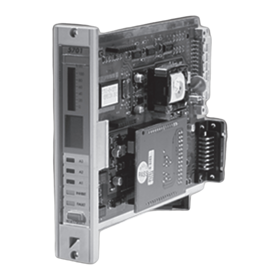
System 57 Quick Start Guide 05701-M-5026 MAN0839 Issue 1 3.5 Engineering Card The System 57 engineering card provides full maintenance and set up facilities for each channel card. The front panel has a series of tactile feedback push buttons that allows checks of the alarm levels and performance to be carried out for each channel. -
Page 6: Dc Input Card
System 57 Quick Start Guide 05701-M-5026 MAN0839 Issue 1 3.9 DC Input Card The DC input card is connected directly to the engineering card and provides the connection point for power supplied to the whole rack. The field wiring from the engineering card is also on this card. -
Page 8: Cabinet And Rack Installation
System 57 Quick Start Guide 05701-M-5026 MAN0839 Issue 1 5 Cabinet and Rack Installation Rear and front access racks outline dimensions Cabinet outline dimensions Power supply outline dimensions 6 Detector Installation Always install the detectors in accordance with the Detector Operating Instructions. In general, detectors for lighter than air gasses should be located at a high level and detectors for heavier than air gasses should be located at a low level. -
Page 9: Interface Card Connections
System 57 Quick Start Guide 05701-M-5026 MAN0839 Issue 1 7 Interface Card Connections System 57 interface cards use a common card with differing numbers of terminal blocks fitted according to which type of card it is. The picture below illustrates a card with the maximum number of terminals fitted. -
Page 10: Detector Connections
System 57 Quick Start Guide 05701-M-5026 MAN0839 Issue 1 8 Detector Connections The following sections show generic installation schematics for the most common types of fire or gas detector and System 57. 8.1 Cable Earthing/Grounding The detector cable screen or steel wire armour (or braid), as appropriate, should be connected to the system (protective) earth. -
Page 11: 4-20Ma Loop Powered Detector (Measuring Resistor In Supply Return)
System 57 Quick Start Guide 05701-M-5026 MAN0839 Issue 1 8.3.1 4-20mA loop powered detector (measuring resistor in supply return) Sensor Drive Module Link Positions 13, 10 & 4. Detector 5701 Interface Card 8.3.2 4-20mA loop powered detector (measuring resistor in supply positive line) Sensor Drive Module Link... -
Page 12: Wire Source Transmitter (Sink Card)
System 57 Quick Start Guide 05701-M-5026 MAN0839 Issue 1 Transmitters powered from the 5701 Control Card require either three or four wire connections and the detector documentation will indicate the 0V and +24V power connections and the positive and negative loop connections. At the System 57 end of the field cable the detector wires should be connected to the S, 01, NS, 0V or 24V terminals on the Field Interface or Relay Card that is attached to the required Single Channel Display Card. -
Page 13: 5704 Gas Card And Catalytic Type Detector
System 57 Quick Start Guide 05701-M-5026 MAN0839 Issue 1 8.5 5704 Gas Card and Catalytic Type Detector Catalytic detectors require a three wire connection and the detector documentation will indicate three connections S, 01 and NS, which are usually brown, white and blue respectively. -
Page 14: 5704 Gas Card And 3 Wire 4-20Ma Transmitter
System 57 Quick Start Guide 05701-M-5026 MAN0839 Issue 1 8.7 5704 Gas Card and 3 Wire 4-20mA Transmitter Transmitters require either three or four wire connections and the dete ctor documentation will indicate the 0V and +24V power connections and the positive and negative loop connections. -
Page 15: 5704 Fire Card
System 57 Quick Start Guide 05701-M-5026 MAN0839 Issue 1 8.8 5704 Fire Card The 5704F fire input circuit operates from the system dc input supply (21 to 32V) but has a built-in voltage limiter that limits the maximum loop voltage to +24V to protect the detectors from damage. -
Page 16: Typical Loop Powered Detector Connections
System 57 Quick Start Guide 05701-M-5026 MAN0839 Issue 1 8.8.2 Typical Loop Powered Detector Connections Loop powered detectors (e.g. most smoke, heat and manual call points) have two wire connection. The detector documentation will indicate the positive and negative loop connections. -
Page 17: Separately Powered Detectors
System 57 Quick Start Guide 05701-M-5026 MAN0839 Issue 1 Hazardous Area Safe Area Fuse 5.1k Safety Barrier Detectors e.g. MTL 728 5704 Hex Card The diagram shows the detector connections for Channel 1. Channel 2, 3 and 4 connections are similar and their terminal connection numbers are shown in section 7. Notes: 1. -
Page 18: Call Points And Simple Switched Output Detectors
System 57 Quick Start Guide 05701-M-5026 MAN0839 Issue 1 The detector cable screen, or steel wire armour or braid as appropriate, should be connected to the system protective earth. This can be achieved where the cable enters the cabinet by using a metal cable gland, or by other suitable means, and avoiding any screen tails within the cabinet. -
Page 19: Detectors With Voltage Free Contact Outputs
System 57 Quick Start Guide 05701-M-5026 MAN0839 Issue 1 Where the cable consists of a separate screen sheath and wire armour or braid, the armour should be co nnected at the cabinet entry to the protective earth and the screen sheath should be connected to the GROUND terminal of the Hex Relay Interface Card or to a suitable instrument earth point. - Page 20 System 57 Quick Start Guide 05701-M-5026 MAN0839 Issue 1 should be connected to the GROUND terminal of the Hex Relay Interface Card or to a suitable instrument earth point. Alarm Current Resistor Normally Closed Fault Contact 5.1k Normally Open Alarm Contact Volt Free Output Detector 5704 Hex Card The diagram shows the detector connections for Channel 1.
-
Page 21: Specification
System 57 Quick Start Guide 05701-M-5026 MAN0839 Issue 1 9 Specification 9.1 Approvals and Standards Designed to comply with: EN50054 General Requirements (Combustible Gases). EN50057 Performance (100 LEL). EN50058 Performance (100 V/V). EN50271 Software and Digital Technologies. Meets Exe isolation requirements for 50V operation. EXAM BBG Pruef- und Zertifizier GmbH, EC-type examination certificate BVS 04 ATEX G 001 X. -
Page 22: Environmental
System 57 Quick Start Guide 05701-M-5026 MAN0839 Issue 1 9.2 Environmental º º Operating Temperature: C* to +55 C (*0° for EXAM approved systems). º º Storage Temperature: C to +55 Humidity: 0 to 90% RH. Non-condensing. 9.3 RFI/EMC Conformity EMC Directive 89/336/EEC Conforms to: EN 50270:1999 Special conditions: The optional recorder output may be in error by ±5% fsd during some test conditions of the industrial standard if the connecting cables are not shielded with an... -
Page 23: Special Conditions For Safe Use
System 57 Quick Start Guide 05701-M-5026 MAN0839 Issue 1 10 Special Conditions For Safe Use. ACCORDING TO EC-TYPE EXAMINATION CERTIFICATE BVS 04 ATEX G 001 X The following special properties have to be considered at operation of the control unit: When operated with remote detectors with 4-20mA interface the specifications of the 4-20mA interface and the behaviour below 4mA and above 20mA have to be considered. - Page 24 Thank you for reading this data sheet. Please contact us for a quotation: Head Office (UK) Switzerland Office P.O. Box 2124 Zugerstrasse 46 Chelmsford 6314 Unterägeri Essex CM1 3UP England Switzerland Tel: +44 (0)1245 600 560 Tel: +41 41 541 5877 Fax: +44 (0)1245 600 030 Fax: +41 41 541 5878 Email:...