Table of Contents
Advertisement
Mcac-Tsm-2008-02
Part 1 General Information ........................................................................2
Part 2 Outdoor Units ...................................................................................7
Part 3 Installation......................................................................................63
Part 4 Controller .......................................................................................79
Contents
Contents
i
Advertisement
Table of Contents

Related Manuals for Midea MGC-F05W/N1


Summary of Contents for Midea MGC-F05W/N1
- Page 1 MCAC-TSM-2008-02 Contents Part 1 General Information ................2 Part 2 Outdoor units ...................7 Part 3 Installation..................63 Part 4 Controller ..................79 Contents...
-
Page 3: Mcac-Tsm
MCAC-TSM-2008-02 Introduction Introduction Midea Mini Unitary Chiller is air-cooled chiller and heat pump system, the chiller itself built in with water pump, expansion tank, plate heat-exchanger; it is very simple for installer to install such kind of system. Expansion Tank... - Page 4 General Information MCAC-TSM-2008-02 Part 1 General Information 1. Model Names of Outdoor Units........3 2. External Appearance ............4 3. Nomenclature ..............5 4. Features .................6 General Information...
-
Page 5: Model Names Of Outdoor Units
MCAC-TSM-2008-02 Model Names of Outdoor Units 1. Model Names of Outdoor Units Model Refrigerant Capacity Power Supply(V-ph-Hz) MGC-F05W/N1 R410A 5.0kW 220~240-1-50 MGC-F07W/N1 R410A 7.2kW 220~240-1-50 MGC-F09W/N1 R410A 9.0kW 220~240-1-50 MGC-F10W/N1 R410A 10.5kW 220~240-1-50 MGC-F10W/SN1 R410A 10.5kW 380~415-3-50 MGC-F12W/SN1 R410A 12.0kW... -
Page 6: External Appearance
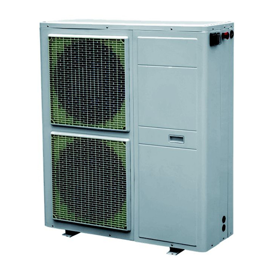
External Appearance MCAC-TSM-2008-02 2. External Appearance MGC-F05W/N1 MGC-F07W/N1 MGC-F09W/N1 MGC-F10W/(S)N1 MGC-F12W/SN1 MGC-F14W/SN1 MGC-F16W/SN1 General Information... -
Page 7: Nomenclature
MCAC-TSM-2008-02 Nomenclature 3. Nomenclature MGC - F 14 W / S N1 Refrigerant N1 R410A Power Supply S: 380-415V, 50Hz, 3ph --: 220-240V, 50Hz, 1ph Outdoor Unit Capacity(14kW) F: Fixed Speed Type Midea Mini Unitary Chiller General Information... -
Page 8: Features
Features MCAC-TSM-2008-02 4. Features Adopts R410A refrigerant, friendly to our environment. Compact design: built-in with water pump and expansion tank, only need to connect the water pipe, making simple installation. Built-in with emergency switch: switch off the unit manually in any emergency case. Water pressure gauge: Inspect the water pressure any time Emergency switch: Stop the chiller directly by the switch in any urgent case... -
Page 9: Table Of Contents
MCAC-TSM-2008-02 Outdoor units Part 2 Outdoor units 1. Specification ..............8 2. Dimensions (unit: mm) ..........12 3. Service Space (unit: mm) ...........15 4. Piping Diagram............16 5. Wiring Diagrams............17 6. Electric Characteristics ..........20 7. Capacity Tables ............21 8. Operation Limits............37 9. Sound Level..............39 10. - Page 10 Specification MCAC-TSM-2008-02 1. Specification Model MGC-F05W/N1 MGC-F07W/N1 Power supply V-Ph-Hz 220-240, 1, 50 220-240, 1, 50 Capacity Cooling Input 1938 2755 Capacity Heating Input 1987 2834 Max. input consumption 2350 3200 Max. input current 11.7 16.7 Starting current 36.8 Model...
- Page 11 MCAC-TSM-2008-02 Outdoor units Model MGC-F09W/N1 MGC-F10W/N1 Power supply V-Ph-Hz 220-240, 1, 50 220-240 , 1, 50 Capacity 10.5 Cooling Input 3540 3614 Capacity Heating Input 3820 4004 Max. input consumption 4950 5500 Max. input current 23.1 25.7 Starting current Model ZP50K3E-PFZ-522 ZP50K3E-PFZ-522 Type...
- Page 12 Specification MCAC-TSM-2008-02 Model MGC-F10W/SN1 MGC-F12W/SN1 Power supply V-Ph-Hz 380-415 , 3, 50 380-415 , 3, 50 Capacity 10.5 Cooling Input 3930 4410 Capacity Heating Input 4240 4643 Max. input consumption 4400 5000 Max. input current Starting current Model ZP50K3E-TFD-522 C-SBN373H8D Type SCROLL SCROLL...
- Page 13 MCAC-TSM-2008-02 Outdoor units Model MGC-F14W/SN1 MGC-F16W/SN1 Power supply V-Ph-Hz 380-415 , 3, 50 380-415 , 3, 50 Capacity Cooling Input 4859 6430 Capacity 16.12 Heating Input 5218 6444 Max. input consumption 6550 7700 Max. input current 10.5 14.3 Starting current Model C-SBN453H8D C-SBN523H8D...
-
Page 14: Dimensions (Unit: Mm)
Specification MCAC-TSM-2008-02 2. Dimensions (unit: mm) 2.1 MGC-F05W/N1 MGC-F07W/N1 Installation... - Page 15 MCAC-TSM-2008-02 Outdoor units 2.2 MGC-F09W/N1 MGC-F10W/N1 MGC-F10W/SN1 Outdoor units...
- Page 16 Specification MCAC-TSM-2008-02 2.3 MGC-F12W/SN1 MGC-F14W/SN1 MGC-F16W/SN1 Installation...
-
Page 17: Service Space (Unit: Mm)
MCAC-TSM-2008-02 Outdoor units 3. Service Space (unit: mm) Dimension MGC-F05W/N1 MGC-F07W/N1 MGC-F09W/N1 1245 MGC-F10W/N1 1245 MGC-F10W/SN1 1245 MGC-F12W/SN1 1070 1249 MGC-F14W/SN1 1070 1249 MGC-F16W/SN1 1070 1249 Outdoor units... -
Page 18: Piping Diagram
Specification MCAC-TSM-2008-02 4. Piping Diagram Remark: Name Name Name Compressor Capillary Water differential pressure switch High pressure switch Liquid receiver Accumulator 4-way valve Plate heat exchanger Low pressure switch Condenser Defrost heater Crankcase heater Filter Water temperature sensor Installation... -
Page 19: Wiring Diagrams
MCAC-TSM-2008-02 Outdoor units 5. Wiring Diagrams 5.1 MGC-F05W/N1 MGC-F07W/N1 Outdoor units... - Page 20 Specification MCAC-TSM-2008-02 5.2 MGC-F09W/N1 MGC-F10W/N1 Installation...
- Page 21 MCAC-TSM-2008-02 Outdoor units 5.3 MGC-F10W/SN1 MGC-F12W/SN1 MGC-F14W/SN1 MGC-F16W/SN1 Outdoor units...
-
Page 22: Electric Characteristics
Specification MCAC-TSM-2008-02 6. Electric Characteristics Outdoor Unit Power Supply Compressor Model Voltage phase Min. Max. TOCA MGC-F05W/N1 50Hz 220-240V 198V 254V 11.25 10.8 36.8 0.12 MGC-F07W/N1 50Hz 220-240V 198V 254V 17.5 16.6 13.1 0.12 MGC-F09W/N1 50Hz 220-240V 198V 254V 24.5 19.5... -
Page 23: Capacity Tables
MCAC-TSM-2008-02 Outdoor units 7. Capacity Tables Cooling MGC-F05W/N1 10.0 25.0 0.88 0.89 0.93 0.95 0.96 1.00 ΔPev 21.6 23.0 24.6 26.3 27.8 29.5 30.0 0.84 0.86 0.88 0.91 0.93 0.95 ΔPev 18.4 19.7 22.1 23.6 25.1 26.6 35.0 0.83 0.84 0.86... - Page 24 Specification MCAC-TSM-2008-02 MGC-F07W/N1 10.0 25.0 1.26 1.27 1.31 1.32 1.34 1.38 ΔPev 35.6 37.0 38.6 40.3 41.8 43.5 30.0 1.22 1.24 1.26 1.29 1.31 1.32 ΔPev 32.4 33.7 36.1 37.6 39.1 40.6 35.0 1.20 1.22 1.24 1.26 1.27 1.29 ΔPev 32.5 33.8 35.0...
- Page 25 MCAC-TSM-2008-02 Outdoor units MGC-F09W/N1 46.4 △ △ 29.5 32.1 35.6 39.0 41.8 47.0 28.0 30.4 33.9 35.0 38.0 △ 24.0 26.0 26.8 28.0 32.1 35.3 △ 20.0 23.5 24.6 28.0 31.0 34.0 △ Note: Ta: outside air temperature (°C) Tw : evaporator water outlet temperature (°C) Pf: cooling capacity (kW) Pa: compressor power input (kW) Pat: total power input (kW)
- Page 26 Specification MCAC-TSM-2008-02 MGC-F10W/N1 10.9 11.2 11.5 11.8 12.1 12.4 31.5 31.7 33.0 33.5 36.0 38.0 △ 10.4 10.8 11.1 11.5 11.8 12.1 △ 29.8 30.4 31.8 33.2 33.6 33.9 10.2 10.5 10.7 11.0 11.3 27.0 27.5 30.0 32.0 32.4 34.0 △...
- Page 27 MCAC-TSM-2008-02 Outdoor units MGC-F10W/SN1 10.9 11.2 11.5 11.8 12.1 12.4 31.5 31.7 33.0 33.5 36.0 38.0 △Pev 10.4 10.8 11.1 11.5 11.8 12.1 △Pev 29.8 30.4 31.8 33.2 33.6 33.9 10.2 10.5 10.7 11.0 11.3 △Pev 27.0 27.5 30.0 32.0 32.4 34.0 10.0...
- Page 28 Specification MCAC-TSM-2008-02 MGC-F12W/SN1 12.4 12.7 13.0 13.3 13.9 29.1 29.9 31.0 32.4 34.1 37.5 △ 11.9 12.2 12.5 12.8 13.1 13.4 △ 23.1 23.2 25.4 27.0 28.8 30.0 11.4 11.7 12.0 12.3 12.6 12.9 21.1 23.2 25.4 27.0 28.8 30.0 △...
- Page 29 MCAC-TSM-2008-02 Outdoor units MGC-F14W/SN1 14.8 15.1 15.4 15.7 16.1 16.4 29.0 29.4 30.4 31.2 33.0 34.0 △ 14.1 14.4 14.7 15.0 15.3 15.6 △ 25.8 28.2 28.4 28.9 29.5 31.0 13.4 13.7 14.0 14.3 14.6 14.9 24.0 25.6 26.0 27.6 28.1 28.4 △...
- Page 30 Specification MCAC-TSM-2008-02 MGC-F16W/SN1 15.5 15.7 16.0 16.3 16.5 16.8 30.5 32.0 33.0 34.5 36.2 37.6 △ 14.8 15.0 15.3 15.6 15.8 16.1 △ 28.3 29.4 28.3 30.4 33.3 35.0 14.9 15.2 15.5 15.8 16.1 16.4 28.2 29.5 31.0 32.3 34.0 35.1 △...
- Page 31 MCAC-TSM-2008-02 Outdoor units Heating MGC-F05W/N1 U.R.87% 0.72 0.72 0.71 ΔPc 14.6 14.5 14.1 0.83 0.83 0.81 0.81 ΔPc 18.5 18.4 18.1 18.1 0.96 0.95 0.95 0.93 ΔPc 23.9 23.4 22.9 1.05 1.05 1.03 1.03 ΔPc 27.8 27.5 27.1 1.12 1.12 1.12...
- Page 32 Specification MCAC-TSM-2008-02 MGC-F07W/N1 U.R.87% 1.10 1.10 1.08 ΔPc 27.6 27.5 27.1 1.20 1.20 1.19 1.19 ΔPc 31.5 31.4 31.1 31.1 1.34 1.32 1.32 1.31 ΔPc 36.9 36.4 35.9 1.43 1.43 1.41 1.41 ΔPc 40.8 40.5 40.1 1.50 1.50 1.50 1.48 ΔPc 46.2 45.9...
- Page 33 MCAC-TSM-2008-02 Outdoor units MGC-F09W/N1 U.R.87% 24.6 24.0 23.7 △ 28.8 28.5 28.1 27.6 △ 48.5 48.2 47.8 47.4 △ △ 56.8 56.2 55.7 55.3 10.2 10.2 10.2 10.1 62.0 61.7 61.4 60.9 △ Note: Ta: outside air temperature (°C) Tw : evaporator water outlet temperature (°C) Pt: heating capacity (kW) Pa: compressor power input (kW) Pat: total power input (kW)
- Page 34 Specification MCAC-TSM-2008-02 MGC-F10W/N1 U.R.87% 19.6 18.9 18.0 △ 27.5 25.6 24.8 23.2 △ 11.4 11.3 11.2 11.1 37.2 35.8 34.5 33.1 △ 12.3 12.2 12.1 12.0 △ 40.5 40.0 39.2 38.8 13.8 13.7 13.6 13.5 45.8 45.1 43.6 42.9 △ Note: Ta: outside air temperature (°C) Tw : evaporator water outlet temperature (°C)
- Page 35 MCAC-TSM-2008-02 Outdoor units MGC-F10W/SN1 U.R.87% 19.6 18.9 18.0 △Pc 27.5 25.6 24.8 23.2 △Pc 11.4 11.3 11.1 11.2 37.2 35.8 33.1 △Pc 34.5 12.3 12.2 12.1 12.0 △Pc 40.5 40.0 39.2 38.8 13.8 13.7 13.6 13.5 △Pc 45.8 45.1 43.6 42.9 Note: Ta: outside air temperature (°C)
- Page 36 Specification MCAC-TSM-2008-02 MGC-F12W/SN1 U.R.87% 26.0 25.6 25.2 △ 11.1 11.0 11.0 11.0 33.0 32.6 32.1 31.8 △ 13.4 13.3 13.2 13.1 44.0 43.6 43.1 42.8 △ 14.4 14.3 14.2 14.1 △ 38.0 37.6 37.2 37.0 15.9 15.8 15.7 15.6 45.0 44.8 44.6 44.2...
- Page 37 MCAC-TSM-2008-02 Outdoor units MGC-F14W/SN1 U.R.87% 10.4 10.5 10.6 15.2 15.1 15.0 △ 13.1 13.0 13.0 12.9 21.1 21.1 21.0 20.9 △ 16.2 16.2 16.1 16.0 31.2 31.1 31.0 31.0 △ 17.6 17.5 17.4 17.4 17.6 17.5 17.4 17.4 17.6 17.5 17.4 17.4 △...
- Page 38 Specification MCAC-TSM-2008-02 MGC-F16W/SN1 U.R.87% 10.5 10.4 10.3 13.9 13.9 13.8 △ 12.8 12.7 12.6 12.5 20.2 20.1 19.9 △ 15.6 15.5 15.5 15.4 30.2 30.1 △ 16.9 16.8 16.7 16.6 △ 35.4 35.2 34.8 18.9 18.8 18.7 46.2 45.6 44.4 △...
-
Page 39: Operation Limits
MCAC-TSM-2008-02 Outdoor units 8. Operation Limits Outdoor units... - Page 40 1.72×10 0.93 0.98 0.98 f1 capacity correction factor fk1 compressor power input correction factor fx1 total power input correction factor 8.3 Minimum water volume Model MGC-F05W/N1 MGC-F07W/N1 MGC-F09W/N1 Minimum water content (L) Model MGC-F10W/(S)N1 MGC-F12W/SN1 MGC-F14W/SN1 MGC-F16W/SN1 Minimum water content (L)
-
Page 41: Sound Level
MCAC-TSM-2008-02 Outdoor units 9. Sound Level Outdoor Unit Microphone 1.0m Unit Number Model Noise level (dB(A)) MGC-F05W/N1 MGC-F07W/N1 MGC-F09W/N1 58/49 MGC-F10W/N1 60/50 MGC-F10W/SN1 58/48 MGC-F12W/SN1 59/49 MGC-F14W/SN1 60/50 MGC-F16W/SN1 60/51 Outdoor units... -
Page 42: Exploded View
Specification MCAC-TSM-2008-02 10. Exploded View 10.1 MGC-F05W/N1 Installation... - Page 43 MCAC-TSM-2008-02 Outdoor units Part Name Quantity Part Name Quantity Rear net Grille Baffle ass'y Axial flow fan Rear net clap Bearing base Condenser ass'y Heat-exchanger base ass'y Condenser inlet pipe ass'y Clamp Condenser outlet pipe ass'y Shield pump ass'y Condenser Valve Condenser side board Expansion vessel...
- Page 44 Specification MCAC-TSM-2008-02 10.2 MGC-F07W/N1 Installation...
- Page 45 MCAC-TSM-2008-02 Outdoor units Part Name Quantity Part Name Quantity Rear net Grille Baffle ass'y Axial flow fan Rear net clap Bearing base Condenser ass'y Heat-exchanger base ass'y Condenser Clamp Condenser inlet pipe ass'y Shieled pump ass'y Condenser outlet pipe ass'y Valve E-part box ass'y Expansion vessel...
- Page 46 Specification MCAC-TSM-2008-02 10.3 MGC-F09W/N1 MGC-F10W/N1 Installation...
- Page 47 MCAC-TSM-2008-02 Outdoor units Part name Quantity Part name Quantity Differential pressure valve below joint pipe Rear support board II assembly Condenser water-up pipe assy subassembly Condenser outlet subassembly water-inlet pipe assy subassembly Condenser inlet subassembly Liquid storage pot connect pipe subassembly Expansion vessel Plate Heat-exchanger assy assembly Accumulator cylinder...
- Page 48 Specification MCAC-TSM-2008-02 10.4 MGC-F10W/SN1 Installation...
- Page 49 MCAC-TSM-2008-02 Outdoor units Part Name Quantity Part Name Quantity Rear support board II 24.1 Water charge valve Condenser 24.2 Safety valve Fluted pipe ass'y 24.3 Water-inlet pipe adapter Input pipe ass'y Connecting pipe ass'y of liquid accumulator Expansion vessel 25.1 Capillary Accumulator cylinder 25.2...
- Page 50 Specification MCAC-TSM-2008-02 10.5 MGC-F12W/SN1 MGC-F16W/SN1 Installation...
- Page 51 MCAC-TSM-2008-02 Outdoor units Part Name Quantity Part Name Quantity Condenser ass'y 23.2 Rubber gasket Partition board ass'y 23.3 Electric heating strip Expansion vessel 23.4 Plate Heat-exchanger Accumulator cylinder 4-way valve ass'y Drain Pump 24.1 4-way valve Rear net clip 24.2 Pipe joint Expansion tank joint pipe ass'y 24.3...
- Page 52 Specification MCAC-TSM-2008-02 10.6 MGC-F14W/SN1 Installation...
- Page 53 MCAC-TSM-2008-02 Outdoor units Part name Quantity Part name Quantity Condenser assembly Handle Middle partition plate subassembly Adapter, drain pipe Expansion vessel Display cover subassembly Accumulator cylinder Bearing Water Pump Left fixing board Rear net clip Plate Heat-exchanger assy assembly Differential pressure valve tie-in Expansion tank joint pipe assembly 23.1 subassembly...
-
Page 54: Troubleshooting
Specification MCAC-TSM-2008-02 11. Troubleshooting Displaying contents Malfunction or protection Remote switch in Standby position (automatic reset) Er01 High pressure protection ( manual reset ) Er05 Low pressure protection Er41 3-phase sequence, current and over-heat condenser temperature protection (manual reset) Er30 Frost prevention alarm (manual reset) Er61 Water outlet sensor T02 malfunction (automatic reset) - Page 55 MCAC-TSM-2008-02 Outdoor units 2. Er01 High pressure>4.4MPa, display Er01, compressor and outdoor fan stop, the chiller can only resume from protection manually. Values display indication Er01 Refer to the instruction manual: High pressure protection Judge 1: check the high pressure switch is well. Replace the high pressure switch Judge 2: Whether the temperature of external and inlet water is high Check the operation conditions:...
- Page 56 Specification MCAC-TSM-2008-02 Low pressure protection (code: Er05) Low pressure<0.15MPa, display Er05, compressor and outdoor fan stop; Low pressure>0.3MPa, compressor and outdoor fan restart (3 minutes delay necessary) If Er05 appears 3 times in 1hour, the chiller can only resume from protection manually. Values display indication Er05 Refer to the instruction manual: Low pressure protection Judge 1: check the low pressure switch is well.
- Page 57 MCAC-TSM-2008-02 Outdoor units Electric protection Er41 Phase protection of power supply: When the chiller is powered on, if there is wrong sequence of power phase, lack of power phase, it will show Er41, the chiller can not run. Compressor current protection: If the operating current of compressor reaches the value below, system stops and shows Er41: Capacity ( kW) Compressor current value (A)
- Page 58 Specification MCAC-TSM-2008-02 Error code Er30: Values display indication Er30 Refer to the instruction manual: Frost prevention alarm. Judge 1: Whether the unit has electric, because: When water outlet temperature (T02)<4 , water pump and ℃ Supply the power. electric heater start working, when...
- Page 59 MCAC-TSM-2008-02 Outdoor units Error code Er61: Values display indication Er61 Refer to the instruction manual: Water delivery sensor T02 malfunction. Judge 1: Whether the sensor falls off. Insert it well. Judge 2: Check the electrical connection, Connects it well. whether the sensor connects well. Replace water delivery Judge 3: Whether the water delivery sensor T02 sensor T02...
- Page 60 Specification MCAC-TSM-2008-02 Error code Er62: Values display indication Er62 Refer to the instruction manual: Coil sensor T03 malfunction. Judge 1: Whether the sensor falls off. Insert it well. Judge 2: Check the electrical connection, Connect it well. whether the sensor connects well. Replace coil sensor Judge 3: Whether coil sensor T03 is malfunction Judge 4: PCB is malfunction...
- Page 61 MCAC-TSM-2008-02 Outdoor units Error code Er60: Values display indication Er60 Refer to the instruction manual: Water return sensor T01 malfunction. Judge 1: Whether the sensor falls off. Insert it well. Judge 2: Check the electrical connection, Connects it well. whether the sensor connects well. Replace water return Judge 3: Whether water return sensor T01 is sensor T01...
- Page 62 Specification MCAC-TSM-2008-02 Error code Er20: Values display indication Er20 Refer to the instruction manual: Water flow protection. Judge 1: Check whether the differential Close differential pressure switch is close. pressure switch Judge 2: Check whether the pump is Setting the pump in high. setting high.
- Page 63 MCAC-TSM-2008-02 Outdoor units 10. Error code Er47 Values display indication Er47 Refer to the instruction manual: Remote keyboard communication error Judge : Whether the three connecting lines(red, blue and Connect them well in right black) are wrong connected. sequence. 11. Error code Er45/ Er46 Values display indication Er45/ Er46 Refer to the instruction manual: Error clock faulty / Error set clock Set the clock by the controller...
- Page 64 Specification MCAC-TSM-2008-02 12. Error code Er90 Values display indication Er90 Refer to the instruction manual: Alarm history records exceeded 99 times In this condition, it must be recovered by manual reset, please do as follow on the control interface Press [esc + set] in the main screen. The label ‘PAr’ will appear. Scroll with ‘UP’...
-
Page 65: Part 3 Installation
MCAC-TSM-2008-02 Outdoor units Part 3 Installation 1. General Information ............64 2. Description of Standard Unit ........65 3. Installation of Outdoor Unit........66 4. Hydraulic Connection ..........68 5. Electrical Connection ..........71 6. Checking and Starting Up the Unit......74 7. Running and Maintenance .........76 Outdoor units... -
Page 66: General Information
General Information MCAC-TSM-2008-02 1. General Information General warning These units have been designed to chill and heat water and must be used in applications compatible with their performance characteristics; these appliances are designed for residential or similar applications. Incorrect installation, regulation and maintenance or improper use absolves the manufacturer from all liability, whether contractual or otherwise, for damage to people, animals or things. - Page 67 MCAC-TSM-2008-02 Description of Standard Unit 2. Description of Standard Unit These air cooled reverse-cycle chillers with axial-flow fans operate with refrigerant fluid and are suitable for outdoor installation. They are factory tested and on site installation is limited to water and electrical connections. Structure: Panels and base are made from galvanized steel plate painted with epoxy powder to ensure total resistance to atmospheric agents.
-
Page 68: Installation Of Outdoor Unit
Installation of Outdoor Unit MCAC-TSM-2008-02 3. Installation of Outdoor Unit 3.1 Choice of installation site Before installing the unit, agree with the customer the site where it will be installed, taking the following points into consideration: - check that the fixing points are adequate to support the weight of the unit; - pay scrupulous respect to safety distances between the unit and other equipment or structures to ensure that air entering the unit and discharged by the fans is free to circulate. -
Page 69: Service Space
MCAC-TSM-2008-02 Installation of Outdoor Unit 3.3 Service space Dimension MGC-F05W/N1 MGC-F07W/N1 MGC-F09W/N1 1245 MGC-F10W/N1 1245 MGC-F10W/SN1 1245 MGC-F12W/SN1 1070 1249 MGC-F14W/SN1 1070 1249 MGC-F16W/SN1 1070 1249 Installation... -
Page 70: Hydraulic Connection
Hydraulic Connection MCAC-TSM-2008-02 4. Hydraulic Connection The choice and installation of components is the responsibility of the installer who should follow good working practice and current legislation. Before connecting the pipes, make sure they do not contain stones, sand, rust, dross or other foreign bodies which might damage the unit. Construction of a bypass is recommended to enable the pipes to be washed through without having to disconnect the unit (see drain valves). - Page 71 MCAC-TSM-2008-02 Hydraulic Connection close to plate heat exchanger. Provided the pump installed outside of unit, the pump shall be connected at water pipe’s outlet. The pump can be easily installed on the unit by removing the pump connection pipe. Important The chillers must be provided with a filling/top-up system connected to the return line and a drain cock in the lowest part of the installation.
- Page 72 Hydraulic Connection MCAC-TSM-2008-02 Size and position of connections Water Auto-water Security Model (mm) (mm) (mm) (mm) (mm) (mm) inlet/outlet (Ø) replenishing (Ø) discharge (Ø) MGC-F05W/N1 G1/2 G1/2 MGC-F07W/N1 G1/2 G1/2 MGC-F09W/N1 R5/4 G1/2 G1/2 MGC-F10W/N1 R5/4 G1/2 G1/2 MGC-F10W/SN1 R5/4...
-
Page 73: Electrical Connection
MCAC-TSM-2008-02 Electrical Connection 5. Electrical Connection The MGC chillers leave the factory already wired, and require the installation of an omnipolar thermal overload switch, a lockable mains disconnecting switch for the connection to the mains power supply, and the connection of the flow switch to the corresponding terminals. All the above operations must be carried out by qualified personnel in compliance with the legislation in force. - Page 74 Electrical Connection MCAC-TSM-2008-02 Electrical Panel Layout Electrical Power Connection For the functional connection of the unit, bring the power supply cable to the electrical panel inside the unit and connect it to terminals L-N and respecting the (L) phase, (N) neutral and earth in the case of single phase units (220-240V~50Hz), or L1-L2-L3 phases, N neutral and PE earth in three phase units (380~415V-3N-50Hz).
- Page 75 Red/+12v on the module; Important To avoid interference due to magnetic fields, the use of shielded cable is recommended. The cable should not be more than 100m long. The Specification of Power: Type MGC-F05W/N1 MGC-F07W/N1 MGC-F09W/N1 MGC-F10W/N1 Power 220~240-1-50 220~240-1-50...
- Page 76 Checking and Starting Up the Unit MCAC-TSM-2008-02 6. Checking and Starting Up the Unit 6.1 Preparing for first start up Restarting after shutting down for long periods The chiller must be started up for the first time by the Technical Service. Before starting up the chillers, make sure that: All safety conditions have been respected The chiller is adequately fixed to the surface it rests on...
- Page 77 MCAC-TSM-2008-02 Checking and Starting Up the Unit - Use grommet A for the electrical power cable and grommet B for the other external wires. - Replace the inspection panel. - Position the main switch QF1 (outside the unit) in the “ON” position. - The “POWER”...
- Page 78 Running and Maintenance MCAC-TSM-2008-02 7. Running and Maintenance 7.1 Operating characteristics Set point in cooling (factory set) = 10°C, Hysteresis = 3°C. The compressor starts with water temperatures above 13°C. The compressor shuts down with water temperatures of less than 10°C. Set point in heating (factory set) = 45°C, Hysteresis = 3°C.
- Page 79 MCAC-TSM-2008-02 Running and Maintenance 7.2 Routine maintenance Never perform any cleaning operations before having disconnected the unit from the mains power supply. Regular maintenance is fundamental to maintain the efficiency of the unit both in terms of operation and energy consumption. The Technical Assistance Service maintenance plan must be observed, with an annual service which includes the following operations and checks: Filling of the water circuit Presence of air bubbles in the water circuit...
- Page 80 Running and Maintenance MCAC-TSM-2008-02 Prohibition The refrigerant circuit must not be filled with a refrigerant other than that indicated of specification. The use of a different refrigerant may cause serious damage to the compressor. Oxygen, acetylene or other inflammable or poisonous gases must never be used in the refrigerant circuit as they may cause explosion or poisoning.
-
Page 81: Part 4 Controller
MCAC-TSM-2008-02 Running and Maintenance Part 4 Controller 1. Standard Controller ............80 Installation... - Page 82 Standard Controller MCAC-TSM-2008-02 1. Standard Controller ST542 It is built-in with the chiller at the factory. The front panel of the device functions as the user interface and is used to perform all operations relating to the device. 1.1 Introduction of Keys There are 4 keys on the front panel.
- Page 83 MCAC-TSM-2008-02 Standard Controller (folder Par/CF), parameter CF01=0), analogue input AI2 will not be displayed. • For example the hours of functioning of compressor 2 - CP02 - not available on single compressor machines. Label Visibility Description Change Dynamic Analogue inputs Dynamic Digital inputs Dynamic...
- Page 84 Standard Controller MCAC-TSM-2008-02 NOTE: The local ON/OFF function is deactivated if the device has been turned OFF remotely or if a digital input is configured as a remote ON/OFF. Remote on/standby and cooling / heating possibilities Remote control of the unit can be done by a voltage free contact. Depending on the setting on the digital controller, the unit will operate in cooling or in heating mode.
- Page 85 MCAC-TSM-2008-02 Standard Controller 2) Select Operating Mode There are three different operating modes: • Standby mode (StbY) • Heat mode • Cooling mode Instructions are provided below on how to change the operating mode. Controller...
- Page 86 Standard Controller MCAC-TSM-2008-02 3) Select the Clock(CL) Controller...
- Page 87 MCAC-TSM-2008-02 Standard Controller 4) Modifying a parameter Instructions are provided below on how to change a machine parameter. By way of example, let’s look at the CF configuration parameters folder, parameter CF26 (folder PAr/CF/CF26). Controller...
- Page 88 Standard Controller MCAC-TSM-2008-02 5) Set the set point(SP) By way of example, we will change the set point value in COOL mode by 12.0 degrees centigrade to12.5 degrees centigrade. Controller...
- Page 89 MCAC-TSM-2008-02 Standard Controller Controller...
- Page 90 Standard Controller MCAC-TSM-2008-02 6) View and Reset compressor/pump time Example display and reset time (hours x10) for Pump 2 Press the set key from the main display The label Ai will appear on the display. Use the UP and DOWN keys to scroll the other labels until you find the Hr label.
- Page 91 MCAC-TSM-2008-02 Standard Controller The tens of hours of functioning are 2. (Hours expressed in tens: 2 means 20 hours of operation). To clear pump running time PU02, press and hold the [set] key. To reset the hours of functioning of pump PU02, press and hold [set].
- Page 92 Standard Controller MCAC-TSM-2008-02 8) Manual alarm acknowledgment and reset Alarm messages blink. How to acknowledge an alarm is explained below. All error messages are shown in the AL folder (see state Menu) An error message will be shown, alternating with the error alert and the main display.
- Page 93 MCAC-TSM-2008-02 Standard Controller The device will return to the main display. 9) LEDs and Display The display has 18 icons (LEDs) split into 3 categories (+ decimal point): • Decimal point • States and Operating Modes • Values and Units of Measure •...
- Page 94 Standard Controller MCAC-TSM-2008-02 Controller...