Greenheck FD 150 Series Installation Instructions
Extended frame 1.5 hour curtain fire dampers vertical or horizontal mount
Hide thumbs
Also See for FD 150 Series:
Advertisement
Quick Links
INSTALLATION INSTRUCTIONS
FD and DFD 150X
Extended Frame
1
1
⁄
Hour Curtain Fire Dampers
2
Vertical or Horizontal Mount
These instructions apply to 1
masonry, block or stud walls and floors. Specific requirements in
these instructions are mandatory. These instructions meet the
requirements of UL 555. Installation shall comply with the
requirements of NFPA 90A Standard for the Installation of Air
Conditioning and Ventilating Systems. U.L. listing R13317,
California State Fire Marshal listings 3225-981:102 and 3225-
1241:101, and New York City BSA/MEA listing 260-91-M apply
to these dampers.
1. NO ADDITIONAL SLEEVES ARE REQUIRED
The fire damper extended frame is an approved sleeve and
can be properly installed without the need for a supplemental
field installed sleeve. Damper frame shall extend a maximum
of 6" beyond the wall or floor opening on each side.
2. CLEARANCES REQUIRED BETWEEN FIRE DAMPER
SLEEVES AND WALL/FLOOR OPENINGS
Fire damper assemblies expand during periods of intense
heat. Therefore, it is essential that openings in walls or floors
be larger than the fire damper assembly to allow for this
expansion. Minimum clearances required between the
outside of fire damper sleeve assemblies and wall/floor
openings are:
- Galvanized steel fire dampers and sleeves:
damper width and height with a minimum clearance of
Recommended clearances, for width and/or height
dimensions of:
1) 48" or less:
1
⁄
2
2) More than 48" and 96" or less: 1" clearance
3) More than 96": 1
These are total clearances (ignoring fastener heads) and do
not need to be equally spaced around the damper. Refer to
Section 3 and Figure 2 for additional installation
considerations.
Example: A 12" x 12" damper would require a
minimum clearance of
A 48" x 12" damper would require a
minimum clearance of
and
1
⁄
4
Series
1
⁄
hour rated fire dampers mounted in
2
" clearance
1
⁄
" clearance
2
1
⁄
".
4
1
⁄
" on width
2
" on height.
for
1
⁄
" per foot of
8
1
⁄
"
.
4
On types R & CR
factory furnished
duct collar qualifies
as breakaway
connection.
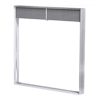
Figure 1: Type A, Type B, and Type C, CO, CR,
VENCO PRODUCTS
1/4" minimum
total clearance
(See Section 2)
Wall or Floor
Maximum
Maximum
6"
Duct
Retaining Angles
(See Section 3)
Type A
Duct
Type B
Duct
Type C, CO, CR & R
R damper installation diagrams.
6"
Damper
Wall or Floor
Damper
Wall or Floor
Damper
Part No.453946
Advertisement

Related Manuals for Greenheck FD 150 Series


Summary of Contents for Greenheck FD 150 Series
- Page 1 INSTALLATION INSTRUCTIONS FD and DFD 150X Series VENCO PRODUCTS Extended Frame ⁄ Hour Curtain Fire Dampers Vertical or Horizontal Mount 1/4" minimum total clearance These instructions apply to 1 ⁄ hour rated fire dampers mounted in (See Section 2) masonry, block or stud walls and floors. Specific requirements in these instructions are mandatory.
- Page 2 3. SECURING THE FIRE DAMPER TO WALL AND FLOOR OPENINGS. Wall or Floor Min. 1" Fire damper assemblies must be installed in wall Overlap* Retaining Retaining and floor openings using retaining angles on each Angle Angle side of the wall or floor as described below: Sleeve - Retaining angles must be a minimum of 16 gauge steel and have a minimum of 1...
- Page 3 BREAKAWAY CONNECTIONS Traditional Breakaway Style Transverse Joints Transverse joints illustrated in Figure 4 have always Plain “S” Slip Hemmed “S” Slip Double “S” Slip been approved as breakaway connections. SMACNA testing has also approved the following variations as breakaway connections. •...
- Page 4 Recommended Preparation of Openings in Wood and Metal Stud Walls - Frame wall openings as shown in Figure 7. - Double vertical studs are not required for openings 36" x 36" or smaller. - Gypsum wall board must be fastened 12" on center to all stud and runner flanges surrounding opening (see Figure 8). - All construction and fasteners must meet the requirements of the appropriate wall design.