Advertisement
Table of Contents
- 1 Safety Information
- 2 Front Panel Illustration
- 3 Rear Panel Illustration
- 4 Lcd Display Illustration
- 5 Inductance/ Capacitance/ Resistance Measurement
- 6 General Specification
- 7 Electrical Specification
- 8 Resistance (Parallel Mode)
- 9 Capacitance (Parallel Mode)
- 10 Inductance (Series Mode)
- 11 Maintenance
- Download this manual
ON
OFF
ON
OFF
This guide provides an overview. Detail User Manual is available
on the accompanying CD-ROM. Please execute the program of
"LCR.HTM " in the CD-ROM, it will guide you to find the related
P/N: 91-25177-1
Copyright© 2004 LT. All rights reserved.
Revised Version: V1.0 on 2004/5/25
Quick Start Guide
REC
D/Q/ θ
RS232
HOLD
ALWAYS DISCHARGE THE CAPACITOR BEFORE TESTING
FORCE
u
u
RS232
REC
RS232
HOLD
D/Q/
ALWAYS DISCHARGE THE CAPACITOR BEFORE TESTING
FORCE
u
u
RS232
document.
AUTO
P
S
CAL
FREQ
RANGE
L/C/R
TOL
REL
SENSE
SENSE
FORCE
AUTO
P
S
CAL
θ
FREQ
RANGE
L/C/R
TOL
REL
SENSE
SENSE
FORCE
Print in Taiwan
Advertisement
Table of Contents

Related Manuals for Escort ELC-3133A


Summary of Contents for Escort ELC-3133A
- Page 1 Revised Version: V1.0 on 2004/5/25 Quick Start Guide AUTO D/Q/ θ RS232 HOLD FREQ RANGE L/C/R ALWAYS DISCHARGE THE CAPACITOR BEFORE TESTING FORCE SENSE SENSE FORCE RS232 AUTO θ RS232 HOLD D/Q/ FREQ RANGE L/C/R ALWAYS DISCHARGE THE CAPACITOR BEFORE TESTING FORCE SENSE SENSE...
-
Page 2: Safety Information
SAFETY INFORMATION In this manual, "WARNING", is reserved for conditions and actions that pose hazard(s) to the user; "CAUTION", is reserved for conditions and actions that may damage your meter. Before using the meter, read the following safety information carefully. 1. - Page 3 INTRODUCTION The meter is a bench type instrument for testing inductance, capacitance and resistance. If this device is damaged or something is missing, contact the place of purchase immediately. This 19,999-count L/C/R meter is a special microprocessor-controlled meter for measuring functions of inductance, capacitance and resistance.
-
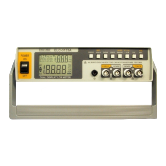
Page 4: Front Panel Illustration
FRONT PANEL ILLUSTRATION 3 4 5 6 7 8 9 10 Figure-1. Front panel POWER SWITCH: used to turn the power ON and OFF. LCD display RS232: Press this button to toggle RS232 function On/OFF. HOLD (REC): Press this button to hold data. Press this button for more than 1 second to enter Static Recording for Maximum, Minimum and Average reading. -
Page 5: Rear Panel Illustration
REAR PANEL ILLUSTRATION Figure-2. Rear Panel. 1. Optical RS-232 interface port. 2. Power cord socket. 3. Line voltage selector and fuse holder: to select line voltage and fuse replacement. CAUTIONS In order to avoid damaging this instrument, make sure that the unit is set to the correct line voltage for your area. -
Page 6: Lcd Display Illustration
LCD DISPLAY ILLUSTRATION 3 4 6 10 RS232 Figure-3. LCD Display. AUTO: Auto-ranging indicator LCR: L, C or R function indicator MAX: Maximum reading indicator AVG: Average reading indicator REL: Relative mode indicator MIN: Minimum reading indicator DH: Data hold indicator Θ: Phase angle indicator Q: Quality factor indicator 10. - Page 7 18. 1%5%10%20%: Tolerance sorting (percent) indicator : Non-used. : Non-used. 21. PAL: Parallel mode indicator 22. SER: Series mode indicator 23. MkΩ: Resistance (Ohm) indicator : Inductance (Henry) indicator : Capacitance (Farad) indicator : RS232 indicator Special Indication Characters : Indicates short connectors : Indicates open connectors : Indicates calibration mode : Indicates damaged or open fuse...
-
Page 8: Inductance/ Capacitance/ Resistance Measurement
MEASURING L/CR Inductance/ Capacitance/ Resistance Measurement Press “L/C/R” button to select inductance (L), capacitance (C) or resistance (R) measurement. Connect the BNC ends of red clip or SMD Tweezers to “SENSE +” and “FORCE +”, respectively. Connect the BNC ends of black clip or SMD Tweezers to “SENSE -”... - Page 9 WARNING To avoid electrical hazards, discharge the capacitor to be tested before measuring. AUTO θ RS232 HOLD D/Q/ FREQ RANGE L/C/R ALWAYS DISCHARGE THE CAPACITOR BEFORE TESTING FORCE SENSE SENSE FORCE Red Clip Figure-5. Capacitance Measurement. AUTO θ RS232 HOLD D/Q/ FREQ RANGE...
-
Page 10: General Specification
GENERAL SPECIFICATION Parameters Measured L/C/R/D/Q/ Θ Measuring Circuit Mode Inductance (L) –Defaults to series mode Capacitance/ Resistance (C/R) -Defaults to parallel mode Displays L/C/R: Maximum display 19999 D/Q: Maximum display 999 (Auto Range). Ranging Mode Auto & Manual Measuring Terminals 4 BNC terminals with one ground terminal Test Frequency 100Hz=100 Hz... -
Page 11: Electrical Specification
ELECTRICAL SPECIFICATION Accuracy is expressed as: ± (% of reading + no. of least significant digits) at 23℃± 5℃and <75% R.H. Resistance (Parallel mode) Test Frequency: 100 / 120 Hz Range Maximum Accuracy Specified Note Display 100 Hz/ 120Hz 0.6%+5 After open cal. -
Page 12: Capacitance (Parallel Mode)
Capacitance (Parallel mode) Test Frequency: 100 / 120 Hz Range Maximum Accuracy Spec. Note Display Capacitance 10mF 19.99mF 2.5%+5 5%+100/Cx+5 After short (DF<0.1) (DF<0.1) cal. 1000 μ F 1999.9 μ F 0.6%+5 1%+100/Cx+5 After short (DF<0.1) (DF<0.1) cal. 200 μ F 199.99 μ... - Page 13 Test Frequency: 10 KHz Range Maximum Accuracy Spec. Note Display Capacitance 50 μ F 50.0 μ F 2.0%+10 8%+100/Cx+10 After short (DF<0.1) (DF<0.1) cal. 20 μ F 19.999 μ F 2.0%+6 3.0+100/Cx+8 After short (DF<0.2) (DF<0.2) cal. 2000nF 1999.9nF 1.0%+5 1.0%+100/Cx+6 (DF<0.5) (DF<0.5)
-
Page 14: Inductance (Series Mode)
Inductance (Series mode) Test Frequency: 100 / 120Hz Range Maximum Accuracy (DF<0.5) Spec. Note Display Inductance 1000H 999.9H 0.3%+(Lx 1%+100/Lx+5 After open /10000) %+5 cal. 200H 199.99H 0.3%+(Lx 0.8%+100/Lx+5 /10000)%+5 19.999H 0.3%+(Lx 0.8%+100/Lx+5 /10000)%+5 2000mH 1999.9mH 0.3%+(Lx 0.8%+100/Lx+5 /10000)%+5 200mH 199.99mH 0.8%+(Lx 1.5%+100/Lx+5 After short... - Page 15 Test Frequency: 10 KHz Maximum Accuracy (DF<0.5) Range Spec. Display Inductance Note 1000mH 999.9mH 2.0%+(Lx 1.5%+100/Lx+10 /10000)%+ 8 200mH 199.99mH 0.6%+(Lx 1.5%+100/Lx+10 /10000)%+8 20mH 19.999mH 0.6%+(Lx 2.0%+100/Lx+15 /10000)%+10 1.0%+(Lx 5.0%+100/Lx+20 After 2000µH 1999.9µH /10000)%+10 short cal. Notes: 1. Q Value is the reciprocal of DF. 2.
-
Page 16: Maintenance
MAINTENANCE WARNING To avoid electrical shock, do not perform any service unless you are qualified to do so. Service If the instrument fails to operate, to check line-power, power cord, fuses and test leads, and replaces them if necessary. If the instrument still can’t work, double check operating procedure as described in this instruction manual.