Advertisement
Table of Contents
- 1 Safety Information
- 2 Front Panel Illustration
- 3 Rear Panel Illustration
- 4 Lcd Display Illustration
- 5 Inductance/ Capacitance/ Resistance Measurement
- 6 General Specification
- 7 Electrical Specification
- 8 Resistance (Parallel Mode)
- 9 Capacitance (Parallel Mode)
- 10 Inductance (Series Mode)
- 11 Maintenance
- Download this manual
ON
OFF
ON
OFF
This guide provides an overview. Detail User Manual is available
on the accompanying CD-ROM. Please execute the program of
"LCR.HTM " in the CD-ROM, it will guide you to find the related
P/N: 91-25177-1
Copyright© 2004 LT. All rights reserved.
Revised Version: V1.0 on 2004/5/25
Quick Start Guide
REC
D/Q/ θ
RS232
HOLD
ALWAYS DISCHARGE THE CAPACITOR BEFORE TESTING
FORCE
u
u
RS232
REC
RS232
HOLD
D/Q/
ALWAYS DISCHARGE THE CAPACITOR BEFORE TESTING
FORCE
u
u
RS232
document.
AUTO
P
S
CAL
FREQ
RANGE
L/C/R
TOL
REL
SENSE
SENSE
FORCE
AUTO
P
S
CAL
θ
FREQ
RANGE
L/C/R
TOL
REL
SENSE
SENSE
FORCE
Print in Taiwan
Advertisement
Table of Contents

Related Manuals for Escort ELC-3133A


Summary of Contents for Escort ELC-3133A
- Page 1 Revised Version: V1.0 on 2004/5/25 Quick Start Guide AUTO D/Q/ θ RS232 HOLD FREQ RANGE L/C/R ALWAYS DISCHARGE THE CAPACITOR BEFORE TESTING FORCE SENSE SENSE FORCE RS232 AUTO θ RS232 HOLD D/Q/ FREQ RANGE L/C/R ALWAYS DISCHARGE THE CAPACITOR BEFORE TESTING FORCE SENSE SENSE...
-
Page 2: Safety Information
SAFETY INFORMATION In this manual, "WARNING", is reserved for conditions and actions that pose hazard(s) to the user; "CAUTION", is reserved for conditions and actions that may damage your meter. Before using the meter, read the following safety information carefully. 1. - Page 3 INTRODUCTION The meter is a bench type instrument for testing inductance, capacitance and resistance. If this device is damaged or something is missing, contact the place of purchase immediately. This 19,999-count L/C/R meter is a special microprocessor-controlled meter for measuring functions of inductance, capacitance and resistance.
-
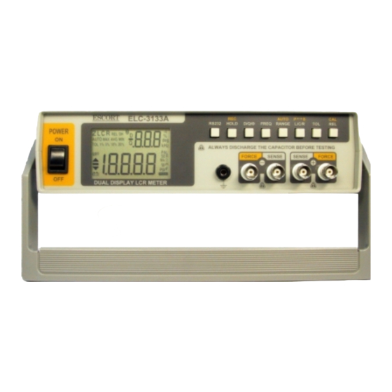
Page 4: Front Panel Illustration
FRONT PANEL ILLUSTRATION 3 4 5 6 7 8 9 10 Figure-1. Front panel POWER SWITCH: used to turn the power ON and OFF. LCD display RS232: Press this button to toggle RS232 function On/OFF. HOLD (REC): Press this button to hold data. Press this button for more than 1 second to enter Static Recording for Maximum, Minimum and Average reading. -
Page 5: Rear Panel Illustration
REAR PANEL ILLUSTRATION Figure-2. Rear Panel. 1. Optical RS-232 interface port. 2. Power cord socket. 3. Line voltage selector and fuse holder: to select line voltage and fuse replacement. CAUTIONS In order to avoid damaging this instrument, make sure that the unit is set to the correct line voltage for your area. -
Page 6: Lcd Display Illustration
LCD DISPLAY ILLUSTRATION 3 4 6 10 RS232 Figure-3. LCD Display. AUTO: Auto-ranging indicator LCR: L, C or R function indicator MAX: Maximum reading indicator AVG: Average reading indicator REL: Relative mode indicator MIN: Minimum reading indicator DH: Data hold indicator Θ: Phase angle indicator Q: Quality factor indicator 10. - Page 7 18. 1%5%10%20%: Tolerance sorting (percent) indicator : Non-used. : Non-used. 21. PAL: Parallel mode indicator 22. SER: Series mode indicator 23. MkΩ: Resistance (Ohm) indicator : Inductance (Henry) indicator : Capacitance (Farad) indicator : RS232 indicator Special Indication Characters : Indicates short connectors : Indicates open connectors : Indicates calibration mode : Indicates damaged or open fuse...
-
Page 8: Inductance/ Capacitance/ Resistance Measurement
MEASURING L/CR Inductance/ Capacitance/ Resistance Measurement Press “L/C/R” button to select inductance (L), capacitance (C) or resistance (R) measurement. Connect the BNC ends of red clip or SMD Tweezers to “SENSE +” and “FORCE +”, respectively. Connect the BNC ends of black clip or SMD Tweezers to “SENSE -”... - Page 9 WARNING To avoid electrical hazards, discharge the capacitor to be tested before measuring. AUTO θ RS232 HOLD D/Q/ FREQ RANGE L/C/R ALWAYS DISCHARGE THE CAPACITOR BEFORE TESTING FORCE SENSE SENSE FORCE Red Clip Figure-5. Capacitance Measurement. AUTO θ RS232 HOLD D/Q/ FREQ RANGE...
-
Page 10: General Specification
GENERAL SPECIFICATION Parameters Measured L/C/R/D/Q/ Θ Measuring Circuit Mode Inductance (L) –Defaults to series mode Capacitance/ Resistance (C/R) -Defaults to parallel mode Displays L/C/R: Maximum display 19999 D/Q: Maximum display 999 (Auto Range). Ranging Mode Auto & Manual Measuring Terminals 4 BNC terminals with one ground terminal Test Frequency 100Hz=100 Hz... -
Page 11: Electrical Specification
ELECTRICAL SPECIFICATION Accuracy is expressed as: ± (% of reading + no. of least significant digits) at 23℃± 5℃and <75% R.H. Resistance (Parallel mode) Test Frequency: 100 / 120 Hz Range Maximum Accuracy Specified Note Display 100 Hz/ 120Hz 0.6%+5 After open cal. -
Page 12: Capacitance (Parallel Mode)
Capacitance (Parallel mode) Test Frequency: 100 / 120 Hz Range Maximum Accuracy Spec. Note Display Capacitance 10mF 19.99mF 2.5%+5 5%+100/Cx+5 After short (DF<0.1) (DF<0.1) cal. 1000 μ F 1999.9 μ F 0.6%+5 1%+100/Cx+5 After short (DF<0.1) (DF<0.1) cal. 200 μ F 199.99 μ... - Page 13 Test Frequency: 10 KHz Range Maximum Accuracy Spec. Note Display Capacitance 50 μ F 50.0 μ F 2.0%+10 8%+100/Cx+10 After short (DF<0.1) (DF<0.1) cal. 20 μ F 19.999 μ F 2.0%+6 3.0+100/Cx+8 After short (DF<0.2) (DF<0.2) cal. 2000nF 1999.9nF 1.0%+5 1.0%+100/Cx+6 (DF<0.5) (DF<0.5)
-
Page 14: Inductance (Series Mode)
Inductance (Series mode) Test Frequency: 100 / 120Hz Range Maximum Accuracy (DF<0.5) Spec. Note Display Inductance 1000H 999.9H 0.3%+(Lx 1%+100/Lx+5 After open /10000) %+5 cal. 200H 199.99H 0.3%+(Lx 0.8%+100/Lx+5 /10000)%+5 19.999H 0.3%+(Lx 0.8%+100/Lx+5 /10000)%+5 2000mH 1999.9mH 0.3%+(Lx 0.8%+100/Lx+5 /10000)%+5 200mH 199.99mH 0.8%+(Lx 1.5%+100/Lx+5 After short... - Page 15 Test Frequency: 10 KHz Maximum Accuracy (DF<0.5) Range Spec. Display Inductance Note 1000mH 999.9mH 2.0%+(Lx 1.5%+100/Lx+10 /10000)%+ 8 200mH 199.99mH 0.6%+(Lx 1.5%+100/Lx+10 /10000)%+8 20mH 19.999mH 0.6%+(Lx 2.0%+100/Lx+15 /10000)%+10 1.0%+(Lx 5.0%+100/Lx+20 After 2000µH 1999.9µH /10000)%+10 short cal. Notes: 1. Q Value is the reciprocal of DF. 2.
-
Page 16: Maintenance
MAINTENANCE WARNING To avoid electrical shock, do not perform any service unless you are qualified to do so. Service If the instrument fails to operate, to check line-power, power cord, fuses and test leads, and replaces them if necessary. If the instrument still can’t work, double check operating procedure as described in this instruction manual.
Need help?
Do you have a question about the ELC-3133A and is the answer not in the manual?
Questions and answers