Table of Contents
Advertisement
Advertisement
Table of Contents

Related Manuals for MSI MS-7222


Summary of Contents for MSI MS-7222
- Page 1 PM8PM MS-7222 (v1.X) Micro-ATX Mainboard G52-72221X1...
- Page 2 VOIR LA NOTICE D’INSTALLATION AVANT DE RACCORDER AU RESEAU. Micro-Star International MS-7222 This device complies with Part 15 of the FCC Rules. Operation is subject to the following two conditions: (1) this device may not cause harmful interference, and...
-
Page 3: Copyright Notice
Copyright Notice The material in this document is the intellectual property of MICRO-STAR INTERNATIONAL. We take every care in the preparation of this document, but no guarantee is given as to the correctness of its contents. Our products are under continual improvement and we reserve the right to make changes without notice. -
Page 4: Technical Support
Alternatively, please try the following help resources for further guidance. † Visit the MSI homepage & FAQ site for technical guide, BIOS updates, driver updates, and other information: http://www.msi.com.tw & http://www.msi. - Page 5 WEEE Statement...
-
Page 8: Table Of Contents
Chapter 1. Getting Started ................1-1 Mainboard Specifications ................1-2 Mainboard Layout ................... 1-4 Packing Contents .................... 1-5 MSI Special Feature ..................1-6 Chapter 2. Hardware Setup ................2-1 Quick Components Guide ................2-2 Central Processing Unit: CPU ................. 2-3 Introduction to LGA 775 CPU .............. - Page 9 BIOS Flash Jumper: JWP1 ..............2-20 Slots ......................2-21 PCI Interrupt Request Routing ............... 2-21 AGP (Accelerated Graphics Port) Slot ..........2-21 PCI (Peripheral Component Interconnect) Slots ........2-21 Chapter 3. BIOS Setup ..................3-1 Entering Setup ....................3-2 The Main Menu ....................3-3 Standard CMOS Features ................
-
Page 10: Chapter 1. Getting Started
Getting Started Chapter 1. Getting Started Getting Started Thank you for choosing the PM8PM(MS-7222 v1.X) Series ® ATX mainboard. The PM8PM mainboard is based on VIA P4M800 ® Pro and VIA VT8237R Plus chipset for optimal system efficiency. ® Designed to fit the advanced Intel... -
Page 11: Mainboard Specifications
MS-7222 Micro-ATX Mainboard Mainboard Specifications CPU* † Supports Intel ® ® Pentium 4/ Prescott (LGA 775) processor. † FSB @ 1066/800/533MHz. † Supports Intel P4 Prescott CPU up to 3.8GHz, and Intel P4 Prescott Celeron CPU. † Supports Dual Core CPU (2.8G only) †... - Page 12 Dimension † Micro-ATX Form Factor: 245mm x 220mm. Mounting † 6 standard mounting holes. *For the latest information about CPU, please visit http://www.msi.com.tw/program/ products/mainboard/mbd/pro_mbd_cpu_support.php ** For the updated supporting memory modules, please visit http://www.msi.com.tw/ program/products/mainboard/mbd/pro_mbd_trp_list.ph 1 - 3...
-
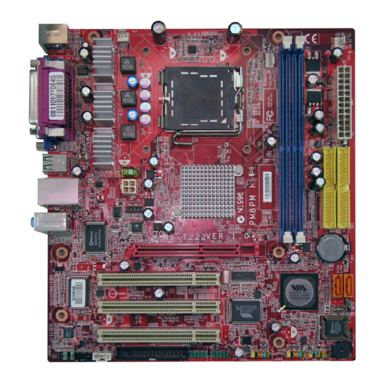
Page 13: Mainboard Layout
Winbond AGP Slot W83627EHF BATT PCI Slot 1 VT8237R RTL8100C PCI Slot 2 PLUS VT6307 (Optional) PCI Slot 3 BIOS AC97 JAUDIO01 CD_IN1 (Optional) (Optional) 1394_J2 1394_J3 JUSB1 JUSB2 JFP1 FDD 1 PM8PM (MS-7222 v1.X) Micro-ATX Mainboard 1 - 4... -
Page 14: Packing Contents
Getting Started Packing Contents MSI Driver/Utility CD SATA Cable MSI motherboard Round Cable for COM2 Bracket IDE Devices Power Cable (Optional) (Optional) Round Cable for Floppy Disk User’s Guide Back IO Shield (Optional) * The pictures are for reference only. Your packing contents may vary depending on the model you purchased. -
Page 15: Msi Special Feature
MS-7222 Micro-ATX Mainboard MSI Special Feature The Core Center is a new utility you can find in the CD-ROM disk. The utility is just like your PC doctor that can detect, view and adjust the PC hardware and system status during real time operation. In the left side it shows the current system status, including the Vcore, 3.3V, +5V and 12V. - Page 16 “OK” to apply the changes. The values you set for the temperatures are the maximum thresholds for the system for warnings, and the value for fan speeds are the minimum thresholds. MSI Reminds You... Items shown on Core Center vary depending on your system status. 1 - 7...
-
Page 17: Chapter 2. Hardware Setup
Hardware Setup Chapter 2. Hardware Setup Hardware Setup This chapter tells you how to install the CPU, memory modules, and expansion cards, as well as how to setup the jumpers on the mainboard. Also, it provides the instructions on connecting the periph- eral devices, such as the mouse, keyboard, etc. -
Page 18: Quick Components Guide
MS-7222 Micro-ATX Mainboard Quick Components Guide CPU_FAN1, p.2-13 JPW2, p.2-8 DDR DIMMs, p.2-7 SYS_FAN1, p.2-13 CONN1, p.2-8 Back Panel I/O, p.2-9 IDE1, p.2-14 COM2, p.2-14 AGP, p.2-21 SATA1,2, p.2-15 JBAT2, PCI Slots 1~3, p.2-20 p.2-21 JPW1, p.2-20 JFP1, p.2-16 JAUDIO1, p.2-17... -
Page 19: Central Processing Unit: Cpu
If you do not have the CPU cooler, contact your dealer to purchase and install them before turning on the computer. For the latest information about CPU, please visit http://www.msi.com.tw/ program/products/mainboard/mbd/pro_mbd_cpu_support.php. MSI Reminds You... -
Page 20: Cpu & Cooler Installation
MS-7222 Micro-ATX Mainboard CPU & Cooler Installation When you are installing the CPU, make sure the CPU has a cooler at- tached on the top to prevent overheating. If you do not have the cooler, contact your dealer to purchase and install them before turning on the computer. Meanwhile, do not forget to apply some silicon heat transfer compound on CPU before installing the heat sink/cooler fan for better heat dispersion. - Page 21 If not, package. take out the CPU with pure vertical motion and reinstall. MSI Reminds You... 1. Confirm if your CPU cooler is firmly installed before turning on your system. 2. Do not touch the CPU socket pins to avoid damaging.
- Page 22 MS-7222 Micro-ATX Mainboard 9. Press down the load lever lightly 10. Align the holes on the mainboard onto the load plate, and then se- with the heatsink. Push down the cure the lever with the hook under cooler until its four clips get retention tab.
-
Page 23: Memory
The plastic clip at each side of the DIMM slot will automatically close. Notch Volt MSI Reminds You... You can barely see the golden finger if the module is properly in- serted in the socket. 2 - 7... -
Page 24: Power Supply
MS-7222 Micro-ATX Mainboard Power Supply The mainboard supports ATX power supply for the power system. Before inserting the power supply connector, always make sure that all components are installed properly to ensure that no damage will be caused. ATX 24-Pin Power Connector: CONN1 The mainboard supports ATX power supply for the power system. -
Page 25: Back Panel
Hardware Setup Back Panel The back panel provides the following connectors: L-In Parallel M ouse (optional) USB Ports COM Port VGA Port L-Out Keyboard Mouse/Keyboard Connector ® The mainboard provides a standard PS/2 mouse/keyboard mini DIN connector ® ® for attaching a PS/2 mouse/keyboard. -
Page 26: Serial Port Connector
MS-7222 Micro-ATX Mainboard Serial Port Connector The mainboard offers one 9-pin male DIN connector as the serial port. The port is a 16550A high speed communication port that sends/receives 16 bytes FIFOs. You can attach a serial mouse or other serial devices directly to the connector. -
Page 27: Usb Connectors
Tape player, or other audio devices. Mic is a connector for microphones. Line In Line Out MSI Reminds You... For the advanced functions of the audio codec, please refer to Chapter 4: Introduction to Realtek ALC655 for details. 2-11... -
Page 28: Parallel Port Connector: Lpt1
MS-7222 Micro-ATX Mainboard Parallel Port Connector: LPT1 The mainboard provides a 25-pin female centronic connector as LPT. A parallel port is a standard printer port that supports Enhanced Parallel Port (EPP) and Ex- tended Capabilities Parallel Port (ECP) mode. Pin Definition... -
Page 29: Floppy Disk Drive Connector: Fdd1
+12V +12V Sensor SYS_FAN1 CPU_FAN1 MSI Reminds You... 1. Always consult the vendors for proper CPU cooling fan. 2. CPU_FAN1 supports the fan control. Fan/heatsink with 3 or 4 fins are both available. ® 3. Please refer to the recommended CPU fans at Intel official website. -
Page 30: Hard Disk Connectors: Ide1, Ide2
MS-7222 Micro-ATX Mainboard Hard Disk Connectors: IDE1, IDE2 The mainboard has one 32-bit Ultra DMA 66/100 IDE controller integrated in ICH6, which supports PIO & Bus Master operation modes and it can connect up to two Ultra ATA drives. IDE2... -
Page 31: Serial Ata: Sata1,Sata2
Take out the dust cover and connect to the hard disk devices Connect to serial ATA ports MSI Reminds You... Please do not fold the serial ATA cable in a 90-degree angle, since this might cause the loss of data during the transmission. 2-15... -
Page 32: Front Panel Connectors: Jfp1
MS-7222 Micro-ATX Mainboard Front Panel Connectors: JFP1 The mainboard provides one front panel connector for electrical connection to ® the front panel switches and LEDs. JFP1 is compliant with Intel Front Panel I/O Connectivity Design Guide. Reset Switch JFP1 Power... -
Page 33: Front Panel Audio Connector: Jaudio1
Left channel audio signal to front panel AUD_RET_L Left channel audio signal return from front panel MSI Reminds You... If you don’t want to connect to the front audio header, pins 5 & 6, 9 & 10 have to be jumpered in order to have signal output directed to the rear audio ports. -
Page 34: Front Usb Connectors: Jusb1 & Jusb2
MS-7222 Micro-ATX Mainboard Front USB Connectors: JUSB1 & JUSB2 The mainboard provides two standard USB 2.0 pin headers JUSB1 & JUSB2 . USB 2.0 technology increases data transfer rate up to a maximum throughput of 480Mbps, which is 40 times faster than USB 1.1, and is ideal for connecting high- speed USB interface peripherals such as USB HDD, digital cameras, MP3 players, printers, modems and the like. -
Page 35: Ieee 1394 Connectors (Optional): 1394_J2/ 1394_J3
Hardware Setup IEEE 1394 Connectors (optional): 1394_J2/ 1394_J3 The mainboard provides two 1394 pin headers that allows you to connect IEEE 1394 ports via an external IEEE1394 bracket (optional). Pin Definition SIGNAL SIGNAL TPA+ TPA- 1394_J2,1394_J3 Ground Ground TPB+ TPB- Cable power Cable power Key (no pin) -
Page 36: Jumpers
MS-7222 Micro-ATX Mainboard Jumpers The motherboard provides the following jumpers for you to set the computer’s function. This section will explain how to change your motherboard’s function through the use of jumpers. Clear CMOS Jumper: JBAT2 There is a CMOS RAM on board that has a power supply from external battery to keep the system configuration data. -
Page 37: Slots
Hardware Setup Slots The mainboard provides one AGP slot and three 32-bit PCI bus slots. AGP (Accelerated Graphics Port) Slot The AGP slot allows you to insert the AGP graphics card. AGP is an interface specification designed for the throughput demands of 3D graphics. It introduces a 66MHz, 32-bit channel for the graphics controller to directly access main memory. -
Page 38: Chapter 3. Bios Setup
SETUP. ² You want to change the default settings for customized features. MSI Reminds You... 1. The items under each BIOS category described in this chapter are under continuous update for better system performance. -
Page 39: Entering Setup
MS-7222 Micro-ATX Mainboard Entering Setup Power on the computer and the system will start POST (Power On Self Test) process. When the message below appears on the screen, press <DEL> key to enter Setup. Press F1 to continue, DEL to enter SETUP If the message disappears before you respond and you still wish to enter Setup, restart the system by turning it OFF and On or pressing the RESET button. -
Page 40: The Main Menu
BIOS Setup The Main Menu Once you enter BIOS SETUP UTILITY, the Main Menu will appear on the screen. Use arrow keys to move among the items and press <Enter> to enter the sub-menu. Standard CMOS Features Use this menu for basic system configurations, such as time, date etc. Advanced BIOS Features ®... - Page 41 MS-7222 Micro-ATX Mainboard Load Optimized Defaults Use this menu to load the default values set by the mainboard manufacturer specifi- cally for optimal performance of the mainboard. BIOS Setting Password Use this menu to set the password for BIOS. Save & Exit Setup Save changes to CMOS and exit setup.
-
Page 42: Standard Cmos Features
BIOS Setup Standard CMOS Features The items in Standard CMOS Features Menu includes some basic setup items. Use the arrow keys to highlight the item and then use the <+> or <-> keys to select the value you want in each item. Date (mm:dd:yy) This allows you to set the system to the date that you want (usually the current date). - Page 43 MS-7222 Micro-ATX Mainboard DMA Mode This item allows you to enable or disable the DMA (Direct Memory Access) mode. Setting options: [Auto], [Disabled], [UDMA0], [UDMA1], [UDMA2], [UDMA3], [UDMA4], [UDMA5]. Floppy A This item allows you to set the type of the floppy drives installed. Available options: [Disabled], [360 KB, 5 ], [1.2 MB, 5...
-
Page 44: Advanced Bios Features
BIOS Setup Advanced BIOS Features Quick Booting Setting the item to [Enabled] allows the system to boot within 5 seconds since it will skip some check items. Setting options: [Enabled], [Disabled]. CPU Feature Press <Enter> to for the sub-menu of each item: Limit CPUID MaxVal: The item allows you to enable/ disable the CPU ID maximum value. - Page 45 MS-7222 Micro-ATX Mainboard MSI Reminds You... Enabling the functionality of Hyper-Threading Technology for your com- puter system requires ALL of the following platform Components: ® ® * CPU: An Intel Pentium 4 Processor with HT Technology; ® * Chipset: An Intel Chipset that supports HT Technology;...
-
Page 46: Advanced Chipset Features
BIOS Setup Advanced Chipset Features MSI Reminds You... Change these settings only if you are familiar with the chipset. DRAM Clock/Drive Control Press <Enter> and the following sub-menu appears. DRAM Clock Use this field to configure the clock frequency of the installed DRAM. Settings: By SPD, DDR 266 [3:2], DDR 333 [6:5], DDR 400 [1:1], DDR 433, DDR 450, DDR 466, DDR 500, DDR 533. - Page 47 MS-7222 Micro-ATX Mainboard DRAM Timing Selects whether DRAM timing is controlled by the SPD (Serial Presence Detect) EEPROM on the DRAM module. Setting to [Auto By SPD] enables the following fields automatically to be determined by BIOS based on the configurations on the SPD.
- Page 48 BIOS Setup Write to Read CMD (Twtr) This item controls the internal Write to Read Command Delay. Setting options: [1T/ 2T], [2T/3T]. Write Recovery Time (Twr) This function specifies the amount of delay (in clock cycles) that must elapse after the completion of a valid write operation, before an active bank can be precharged.
- Page 49 MS-7222 Micro-ATX Mainboard AGP Driving Value This item specifies an AGP driving force. AGP Fast Write The item enables or disables the AGP Fast Write feature. The Fast Write technol- ogy allows CPU to write directly into the graphics controller without passing anything through system memory and improves 8x speed accordingly.
- Page 50 BIOS Setup VLink 8X Supported This item enables or disables the 8X VLink Data Rate. Setting options: [Enabled], [Disabled]. DRDY_Timing This item allows you to set the DRDY timing. Setting options: [Slowest], [Default], [Optimize]. 3-13...
-
Page 51: Integrated Peripherals
MS-7222 Micro-ATX Mainboard Integrated Peripherals VIA OnChip PCI Device Press <Enter> and the following sub-menu appears. USB Controller This setting is used to enable/disable the onboard USB host controller. Setting options: [Disabled], [Enabled]. USB Device Legacy Support Set to [Enabled] if you need to use any USB 1.1/2.0 device in the operating system that does not support or have any USB 1.1/2.0 driver installed, such as DOS. - Page 52 BIOS Setup Onboard 1394 Controller The item enables or disables the onboard IEEE1394 controller. Setting options: [Enabled], [Disabled]. USB Device Legacy Support Set to [Enabled] if you need to use any USB 1.1/2.0 device in the operating system that does not support or have any USB 1.1/2.0 driver installed, such as DOS and SCO Unix.
- Page 53 MS-7222 Micro-ATX Mainboard I/O Devices Configuration Press <Enter> to enter the sub-menu and the following screen appears: Onboard FDC Controller Select [Enabled] if your system has a floppy disk controller (FDC) installed on the system board and you wish to use it. Setting options: [Enabled], [Disabled].
-
Page 54: Power Management Features
BIOS Setup Power Management Features MSI Reminds You... S3-related functions described in this section are available only when your BIOS supports S3 sleep mode. ACPI Function This item is to activate the ACPI (Advanced Configuration and Power Management Interface) Function. If your operating system is ACPI-aware, such as Windows 98SE/ 2000/ME/XP, select [Enabled]. - Page 55 MS-7222 Micro-ATX Mainboard Suspend Time Out (Minute) If system activity is not detected for the length of time specified in this field, all devices except CPU will be shut off. Settings: [Disabled], [1], [2], [4], [8], [10], [20], [30], [40], [50], [60].
- Page 56 BIOS Setup Resume From S3 By PS/2 Mouse This setting only works Resume From S3 By PS/2 KB is set to [Hot Key]. This setting determines whether the system will be awakened from what power sav- ing modes when input signal of the PS/2 mouse is detected. Setting options: [Disabled], [Enabled].
-
Page 57: Pnp/Pci Configurations
MS-7222 Micro-ATX Mainboard PNP/PCI Configurations This section describes configuring the PCI bus system and PnP (Plug & Play) feature. PCI, or Peripheral Component Interconnect, is a system which allows I/O devices to operate at speeds nearing the speed the CPU itself uses when communicating with its special components. - Page 58 BIOS Setup IRQ Resource Setup Press <Enter> and the following sub-menu appears. IRQ 3/4/5/7/9/10/11/14/15 These items specify the bus where the specified IRQ line is used. The settings determine if AMIBIOS should remove an IRQ from the pool of avail- able IRQs passed to devices that are configurable by the system BIOS.
-
Page 59: H/W Monitor
MS-7222 Micro-ATX Mainboard H/W Monitor This section shows the status of your CPU, fan, overall system status, etc. Monitor function is available only if there is hardware monitoring mechanism onboard. CPU Shutdown Temperature If the CPU temperature reaches the upper limit preset in this setting, the system will be shut down automatically. - Page 60 BIOS Setup PC Health Status Press <Enter> and the following sub-menu appears. CPU/System Temperature, CPU/System FAN Speed, CPU Vcore, 12V, 5V, 5V SB, 3.3V These items display the current status of all of the monitored hardware devices/ components such as CPU voltages, temperatures and all fans’ speeds. 3-23...
-
Page 61: Load Optimized Defaults
MS-7222 Micro-ATX Mainboard Load Optimized Defaults The two options on the main menu allow users to restore all of the BIOS settings to the Optimized values. The Optimized Defaults are the default values set by the mainboard manufacturer specifically for optimal performance of the mainboard. -
Page 62: Chapter 4. Introduction To Realtek Alc655
Chapter 2. Hardware Setup Introduction to Realtek ALC655 The motherboard is equipped with Realtek ALC655 chip, which provides support for 6-channel audio output, including 2 Front, 2 Rear, 1 Center and 1 Subwoofer channel. ALC655 allows the board to attach 4 or 6 speakers for better surround sound effect. -
Page 63: Installing The Audio Driver
MS-7222 Micro-ATX Mainboard Installing the Audio Driver You need to install the driver for Realtek ALC655 chip to function properly before you can get access to 4-/6-channel audio operations. Follow the procedures described below to install the drivers for different operating systems. - Page 64 Introduction to Realtek ALC655 Click Next to start installing files into the system. Click Finish to restart the system. Select this option 4 - 3...
-
Page 65: Using 4- Or 6-Channel Audio Function
MS-7222 Micro-ATX Mainboard Using 4- or 6-Channel Audio Function After installing the audio driver, you are able to use the 4-/6-channel audio feature now. To enable 4- or 6-channel audio operation, first connect 4 or 6 speakers to the appropriate audio connectors, and then select 4- or 6-channel audio setting in the software utility. - Page 66 Introduction to Realtek ALC655 4 - 5...
- Page 67 MS-7222 Micro-ATX Mainboard Connecting the Speakers When you have set the Multi-Channel Audio Function mode properly in the soft- ware utility, connect your speakers to the correct phone jacks in accordance with the setting in software utility. n 2-Channel Mode for Stereo-Speaker Output Refer to the following diagram and caption for the function of each phone jack on the back panel when 2-Channel Mode is selected.
- Page 68 Introduction to Realtek ALC655 n 4-Channel Mode for 4-Speaker Output The audio jacks on the back panel always provide 2-channel analog audio output function, however these audio jacks can be transformed to 4- or 6- channel analog audio jacks by selecting the corresponding multi-channel operation from No.
- Page 69 MS-7222 Micro-ATX Mainboard n 6-Channel Mode for 6-Speaker Output Refer to the following diagram and caption for the function of each jack on the back panel when 6-Channel Mode is selected. Back Panel Line Out (Center and Subwoofer channel) 2 * Line Out (Rear channels)
-
Page 70: Testing The Connected Speakers
Rear Right Rear Left Subwoofer MSI Reminds You... 6 speakers appear on the “Speaker Test” window only when you select “6-Channel Mode” in the “No. of Speakers” column. If you select “4-Channel Mode”, only 4 speakers appear on the window. - Page 71 MS-7222 Micro-ATX Mainboard 4. While you are testing the speakers in 6-Channel Mode, if the sound coming from the center speaker and subwoofer is swapped, you should select Swap Center/ Subwoofer Output to readjust these two channels. Select this function...
-
Page 72: Playing Karaok
Introduction to Realtek ALC655 Playing KaraOK The KaraOK function will automatically remove human voice (lyrics) and leave melody for you to sing the song. Note that this function applies only for 2-channel audio operation. Playing KaraOK 1. Click the audio icon from the window tray at the lower-right corner of the screen. -
Page 73: Chapter 5.Via Vt8237R/ Vt8237R Plus Sata Raid Introduction
VIA VT8237R/ VT8237R Plus SATA RAID Introduction The Southbridge VT8237R/ VT8237R Plus provides a hybrid solution that combines two independent SATA ports for support of up to two Serial ATA (Serial ATA RAID) Appendix. Using 4- or 6-Channel drives. Serial ATA (SATA) is the latest generation of the ATA interface. SATA hard drives Audio Function deliver blistering transfer speeds of up to 150MB/sec. -
Page 74: Introduction
MS-7222 Micro-ATX Mainboard Introduction This section gives a brief introduction on the RAID-related background knowledge and a brief introduction on VIA SATA RAID Host Controller. For users wishing to install their VIA SATA RAID driver and RAID software, proceed to Driver and RAID Soft- ware Installation section. -
Page 75: Bios Configuration
VIA VT8237R/ VT8237R Plus SATA RAID Introduction BIOS Configuration When the system powers on during the POST (Power-On Self Test) process, press <Tab> key to enter the BIOS configuration. The Serial ATA RAID volume may be configured using the VIA Tech. RAID BIOS. Always use the arrow keys to navigate the main menu, use up and down arrow key to select the each item and press <Enter>... -
Page 76: Create Disk Array
MS-7222 Micro-ATX Mainboard Create Disk Array Use the up and down arrow keys to select the Create Array command and press <Enter>. MSI Reminds You... The “Channel”, “Drive Name”, “Mode” and “Size (GB)” in the following example might be different from your system. - Page 77 VIA VT8237R/ VT8237R Plus SATA RAID Introduction After array mode is selected, there are two methods to create a disk array. One method is “Auto Setup” and the other one is “Select Disk Drives”. Auto Setup allows BIOS to select the disk drives and create arrays automatically, but it does not duplicate the mirroring drives even if the user selected Create and duplicate for RAID 1.
-
Page 78: Delete Disk Array
MS-7222 Micro-ATX Mainboard MSI Reminds You... Even though 64KB is the recommended setting for most users, you should choose the block size value which is best suited to your specific RAID usage model. 4KB: For specialized usage models requiring 4KB blocks... -
Page 79: Create And Delete Spare Hard Drive
VIA VT8237R/ VT8237R Plus SATA RAID Introduction Create and Delete Spare Hard Drive If a RAID 1 array is created and there are drives that do not belong to other arrays, the one that has a capacity which is equal to or greater than the array capacity can be selected as a spare drive for the RAID 1 array. -
Page 80: Duplicate Critical Raid 1 Array
MS-7222 Micro-ATX Mainboard Duplicate Critical RAID 1 Array When booting up the system, BIOS will detect if the RAID 1 array has any inconsis- tencies between user data and backup data. If BIOS detects any inconsistencies, the status of the disk array will be marked as critical, and BIOS will prompt the user to duplicate the RAID 1 in order to ensure the backup data consistency with the user data. - Page 81 VIA VT8237R/ VT8237R Plus SATA RAID Introduction 1. Power off and Check the Failed Drive: This item turns off the computer and replaces the failed hard drive with a good one. If your computer does not support APM, you must turn off your computer manually. After replacing the hard drive, boot into BIOS and select Choose replacement drive and rebuild to rebuild the broken array.
-
Page 82: Installing Raid Software & Drivers
Please follow the instruction below to make a VIA Serial ATA RAID driver for yourself. 1. Insert the MSI CD into the CD-ROM drive. 2. Ignore the Setup screen and use “Explorer” to browse the 3. Co py al l t he con te nts (i ncl ud ing th e s ub -fo lde rs) i n t he \\IDE\VIA\Floppy to a fomatted floppy disk. -
Page 83: Installation Of Via Sata Raid Drvier And Utility
† VIA SATA RAID utility † RAID0 and RAID1 functions Insert the MSI CD and click on the VIA SATA/IDE RAID Drivers to install the software. The InstallShield Wizard will begin automatically for installation. Click on the Next button to proceed the installation in the welcoming window. - Page 84 MS-7222 Micro-ATX Mainboard Put a check mark in the check box to install the feature you want. Then click Next button to proceed the installation. Finally, click “Finish” to complete the installation. 5-12...
-
Page 85: Using Via Raid Tool
VIA VT8237R/ VT8237R Plus SATA RAID Introduction Using VIA RAID Tool Once the installation is complete, go to Start ---> Programs --->VIA ---> RAID ---> raid_tool.exe to enable VIA RAID Tool. After the software is finished installation, it will automati- cally started every time Windows is initiated. - Page 86 MS-7222 Micro-ATX Mainboard Click on button to determine the viewing type of left window pane. There are two viewing types: By controllers and by device. Click on the object in the left window pane to display the status of the object in the right windowpane. The following screen shows the status of Array 0---RAID 0.
- Page 87 VIA VT8237R/ VT8237R Plus SATA RAID Introduction You may also use the same button to view the statuses of Array 0- --RAID 1. Click on the plus (+) symbol next to Array 0---RAID 1 to see the details of each disk. 5-15...