Table of Contents
Advertisement
Quick Links
Dealer Setup
& Adjustment Instructions
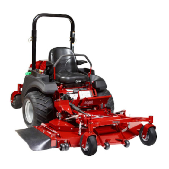
800X Series Zero-Turn Rider • 61" & 72" Mower Deck
This Dealer Setup Instruction covers the following products:
Model No.
Description
5900654
S800XB31
5900658
S800XKAV28
5900656
S800X/61
5900875
S800X/72
ATTENTION SETUP PERSONNEL:
The safety warnings provided in this guide and
in the operator's manual included with the unit
contain important information that must be
obeyed when assembling, setting-up, operating,
servicing, transporting, or storing the unit.
These warnings are highlighted by the safety alert triangle
symbol shown above, which signifies that an important
safety message is being provided.
You must read, understand, and follow these warnings and
instructions, and use safe shop and work practices at all
times while working on or around this unit and all other
outdoor power equipment.
Sections and items denoted by the Setup symbol
provide the information necessary to fully
assemble, test, and prepare the units described
above for delivery to your customers.
A Quick Setup List is provided on page 2 of this booklet
to help you identify and check that the items have been
performed.
Additional information concerning functional
tests, general adjustment procedures, and the
location of normal lubrication points are included
in these instructions.
Although all required lubrication and normal adjustments on
factory-assembled components are done at the factory, this
additional information is provided to assist you in ensuring
that each unit is delivered to the customer in proper working
order.
800X Series Zero-Turn Rider - 61" & 72" Mower Deck
Model No.
Description
5901236
F800XB31
5901237
F800X/61
5901238
F800X/72
TABLE OF CONTENTS:
Quick Setup List..................................................2
Uncrating ..........................................................3
Connect the Battery..............................................3
Tractor Assembly ................................................4
Ground Speed Control Lever Assembly ...........................4
Seat Assembly ..................................................................4
Roll Bar Assembly ...............................................5
Check Fluid levels ...............................................7
Check Engine Oil Level .....................................................7
Check Hydraulic Oil Level .................................................7
Check Tire Pressure .............................................7
Mower Assembly.................................................8
Check Torque - Mower Blades .........................................8
Check Deck Drive Belt ..........................................9
Length (72" Models Only) ................................................9
Length (72" Models Only) ................................................9
Install the Mower Deck ....................................... 10
Adjust Deck Lift Rod Timing ................................. 12
Check & Level the Mower Deck ............................. 13
Deck Lift Spring ................................................ 14
Lubrication ...................................................... 15
Adding Fuel ..................................................... 17
Starting The Engine ........................................... 17
Perform Safety Checks ........................................ 18
Functional Tests .............................................................18
Safety Interlock System .................................................18
Seat Adjustment ............................................... 19
Ground Speed Control Lever Adjustment .................. 20
Speed Balancing Adjustment ................................ 20
Neutral Adjustment ............................................ 21
Return-To-Neutral Adjustment ............................... 22
Parking Brake Adjustment .................................... 23
1
5101742
Rev. J
1
Advertisement
Table of Contents

Related Manuals for Snapper ZTR 800X Series


Summary of Contents for Snapper ZTR 800X Series
-
Page 1: Table Of Contents
800X Series Zero-Turn Rider - 61” & 72” Mower Deck Dealer Setup & Adjustment Instructions 800X Series Zero-Turn Rider • 61” & 72” Mower Deck TABLE OF CONTENTS: This Dealer Setup Instruction covers the following products: SETUP PROCEDURES Model No. Description Model No. -
Page 2: Setup Procedures
800X Series Zero-Turn Rider - 61” & 72” Mower Deck Setup Procedures Quick Setup List Page Setup Procedure Steps to Perform Uncrating Remove Crate & Banding. Loosen Hydraulic Release Valves. Release Parking Brake and Roll Tractor forward off skid. ... -
Page 3: Uncrating
800X Series Zero-Turn Rider - 61” & 72” Mower Deck Uncrating 1. Using a reciprocating utility saw or equivalent, cut the crate away from the bottom skid. Remove the crate. Remove the shrink-wrap plastic. 2. Cut the nylon banding that secures the unit to the crate. NOTICE When cutting the crate from the bottom skid, use caution around the tires and the mower rollers. -
Page 4: Tractor Assembly
800X Series Zero-Turn Rider - 61” & 72” Mower Deck Tractor Assembly Ground Speed Control Lever Assembly 1. Remove the ground speed control lever and mounting hardware from the handle bar box. NOTE: There is a LEFT-HAND and a RIGHT-HAND ground speed control lever . -
Page 5: Roll Bar Assembly
800X Series Zero-Turn Rider - 61” & 72” Mower Deck Roll Bar Assembly Loop End Snap End Assemble Retainer Pins 1. Unpack the roll bar and hardware from the box. 2. Assemble the foam ring (A, Figure 6) onto the retainer pin (B). - Page 6 800X Series Zero-Turn Rider - 61” & 72” Mower Deck 4. Install the top loop (A, Figure 10) onto the upright tubes (B). From the outside, install the 1/2” x 3-1/4” bolt (C) through the retainer pin assembly (D), then through the top loop and upright tube and shown in FIgure 10.
-
Page 7: Check Fluid Levels
800X Series Zero-Turn Rider - 61” & 72” Mower Deck Check Fluid Levels Check Engine Oil Level 1. Raise the hood to gain access to the engine oil dipstick. 2. Use the engine oil dipstick (A, Figure 11) to check the engine oil level. -
Page 8: Mower Assembly
800X Series Zero-Turn Rider - 61” & 72” Mower Deck Check Mower Assembly Check Torque - Mower Blades WARNING Avoid injury! Mower blades are sharp. • Mower blades are sharp. For your personnal safety, do NOT handle mower blades with bare hands. •... -
Page 9: Check Deck Drive Belt
800X Series Zero-Turn Rider - 61” & 72” Mower Deck Check Deck Drive Belt NOTICE To avoid damaging belts, do NOT pry belts over pulleys. 1. Make sure the V-side of the belt runs in the pulley grooves (Figure 15). WARNING Spring loaded components can kick back Figure 15. -
Page 10: Install The Mower Deck
800X Series Zero-Turn Rider - 61” & 72” Mower Deck Install the Mower Deck Installing the Mower Deck 1. Remove the mower deck from the crate and place on a hard, level surface. 2. Install the 1/4” SQ. X 1-1/4” key in the key slot of the gear box shaft. - Page 11 800X Series Zero-Turn Rider - 61” & 72” Mower Deck Positioning the Mower Deck for Operation 1. Turn the ignition key to the ON position and extend the actuator fully by pushing the deck lift switch actuator (B, Figure 21) forward (away from the operator’s position). 2.
-
Page 12: Adjust Deck Lift Rod Timing
800X Series Zero-Turn Rider - 61” & 72” Mower Deck Check the Deck Lift Rod Timing Adjustment 1. Park the machine on a flat, level surface. Disengage the PTO, engage the parking brake, turn off the engine, and remove the ignition key. Drive tires must be inflated to 10 psi (0,69 bar);... -
Page 13: Check & Level The Mower Deck
800X Series Zero-Turn Rider - 61” & 72” Mower Deck Check the Level of the Mower Deck NOTE: Before adjusting the deck level, the deck lift rod timing must be checked and/or adjusted. Coarse Adjustment Procedure When adjusting the deck level, the coarse adjustment procedure should be used to make the majority of the adjustment and the fine adjustment procedure should be used to complete the adjustment. -
Page 14: Deck Lift Spring
800X Series Zero-Turn Rider - 61” & 72” Mower Deck Fine Adjustment Procedure 1. Loosen the jam nut (A, Figure 28) and turn the fine adjustment bolt (B) to adjust the deck height until the front measurement equals 4” (10,2 cm) and the back measurement equals 4”... -
Page 15: Lubrication
800X Series Zero-Turn Rider - 61” & 72” Mower Deck Lubrication Lubricate the unit at the location shown in Figures 30 through 36 as well as the following lubrication points: Grease: • front caster wheel axles & yokes • drive shaft pillow blocks •... - Page 16 800X Series Zero-Turn Rider - 61” & 72” Mower Deck Figure 35. Attachment Lift Arms & Actuator Figure 32. Control Handle Pivots & Seat Plate Pivot Figure 36. Deck Lift Rods Figure 33. Idler Arms A. PTO Clutch Drive Belt Idler Arm B.
-
Page 17: Adding Fuel
800X Series Zero-Turn Rider - 61” & 72” Mower Deck Safety Interlock and Mower Deck Positioning Instructions Adding Fuel This unit is equipped with an safety interlock system to To add fuel: help keep the operator safe while running the unit. Please read and understand the SAFETY INTERLOCK SYSTEM and 1. -
Page 18: Perform Safety Checks
800X Series Zero-Turn Rider - 61” & 72” Mower Deck Perform Safety Checks Safety Interlock System Functional Tests This unit is equipped with safety interlock switches. These safety systems are present for your safety, do not attempt WARNING to bypass safety switches, and never tamper with safety devices. -
Page 19: Adjustment Procedures
800X Series Zero-Turn Rider - 61” & 72” Mower Deck Adjustment Procedures Seat Adjustment Models Equipped with Standard Seat The seat can be adjusted forward and back. S/N: 2014648787 & Below: Move the seat adjustment lever (A, Figure 38) forward, position the seat as desired, and release the lever to lock the seat in position. -
Page 20: Ground Speed Control Lever Adjustment
800X Series Zero-Turn Rider - 61” & 72” Mower Deck Ground Speed Control Lever Adjustment The ground speed control levers can be adjusted in three ways. The alignment of the control levers, the placement of the levers (how close the ends are to one another) and the height of the levers can be adjusted. -
Page 21: Neutral Adjustment
800X Series Zero-Turn Rider - 61” & 72” Mower Deck Neutral Adjustment If the tractor “creeps” while the ground speed control levers are locked in NEUTRAL, then it may be necessary to adjust the linkage rod. 1. Park the machine on a hard, level surface such as a concrete floor. -
Page 22: Return-To-Neutral Adjustment
800X Series Zero-Turn Rider - 61” & 72” Mower Deck Return-to-Neutral Adjustment Checking the Adjustment: To determine if it is necessary to adjust the neutral return, perform the following steps. 1. Disengage the PTO, engage the parking brake and turn off the engine. -
Page 23: Parking Brake Adjustment
800X Series Zero-Turn Rider - 61” & 72” Mower Deck Parking Brake Adjustment 1. Disengage the PTO, engage the parking brake, stop the engine and remove the ignition key. 2. Remove the kick plate (A, Figure 43) 3. Locate the brake spring (A, Figure 44). 4. - Page 24 800X Series Zero-Turn Rider - 61” & 72” Mower Deck Copyright © Briggs & Stratton Corporation Milwaukee, WI, USA. All rights reserved. SNAPPER PRO is a trademark of Briggs & Stratton Corporation, Milwaukee, WI, USA. FERRIS is a trademark of Briggs & Stratton Corporation, Milwaukee, WI, USA.