Table of Contents
Advertisement
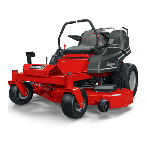
OPERATOR'S
MANUAL
18HP Zero-Turn Riders
Mfg. No.
Description
1694454
Simplicity 18HP Consumer Zero Turn Rider
5091000
Snapper Fast Cut ZT18440KH, 18HP Zero-Turn Rider with 44" Mower
1694744
Massey Ferguson ZT 1844
20HP Zero-Turn Riders
Mfg. No.
Description
1694455
Simplicity 20HP Consumer Zero Turn Rider
1694460
Simplicity 20HP ZT 2050 (CE)
5091001
Snapper Fast Cut ZT20500BV, 20HP Zero-Turn Rider with 50" Mower
5091003
Snapper Fast Cut ZT20500BV, 20HP Zero-Turn Rider with 50" Mower (CE)
1694745
Massey Ferguson ZT 2050
1694781
Massey Ferguson ZT 2050 (CE)
44" Mower Decks
Mfg. No.
Description
1694456
44" Mower Deck
1694459
44" Mower Deck (CE)
1694754
44" Mower Deck
50" Mower Decks
Mfg. No.
Description
1694457
50" Mower Deck
1694461
50" Mower Deck (CE)
1694755
50" Mower Deck
1694782
50" Mower Deck (CE)
Form No. 1725764
05
Revision
Rev.Date 7/2004
TP 100-3885-05-CH-SMN
Advertisement
Table of Contents
Troubleshooting

Related Manuals for Snapper 18HP, 19HP


Summary of Contents for Snapper 18HP, 19HP
- Page 1 1694460 Simplicity 20HP ZT 2050 (CE) 5091001 Snapper Fast Cut ZT20500BV, 20HP Zero-Turn Rider with 50” Mower 5091003 Snapper Fast Cut ZT20500BV, 20HP Zero-Turn Rider with 50” Mower (CE) 1694745 Massey Ferguson ZT 2050 1694781 Massey Ferguson ZT 2050 (CE) 44”...
-
Page 2: Table Of Contents
Safety Rules & Information...2 Identification Numbers...5 Safety Decals ...6 Safety Icons ...7 Safety Interlock System ...7 Features & Controls ...8 Control Functions ...8 Operation ...10 General Operating Safety ...10 Checks Before Starting ...10 Starting the Engine ...11 Stopping the Rider & Engine...11 Mowing...11 Pushing the Rider by Hand ...11 Zero Turn Driving Practice...12... -
Page 3: Safety Rules & Information
Read these safety rules and follow them closely. Failure to obey these rules could result in loss of control of unit, severe personal injury or death to you, or bystanders, or damage to property or equipment. This mowing deck is capable of amputating hands and feet and throwing objects. The triangle in text signifies important cautions or warnings which must be followed. -
Page 4: Safety Rules And Information
SLOPE OPERATION Slopes are a major factor related to loss-of-control and tip- over accidents, which can result in severe injury or death. Operation on all slopes requires extra caution. If you cannot back up the slope or if you feel uneasy on it, do not operate on it. - Page 5 Safety Rules and Information SERVICE AND MAINTENANCE Safe Handling of Gasoline 1. Extinguish all cigarettes, cigars, pipes, and other sources of ignition. 2. Use only approved gasoline containers. 3. Never remove the gas cap or add fuel with the engine running.
-
Page 6: Identification Numbers
K. Vibration at the Steering Wheel * L. Vibration at the Seat * M. Combination Number This unit complies with European Harmonized Lawn Mower Standard EN 836, European Machinery Directive 98/37/EC, and European EMC Directive 89/336/EC * Tested according to EN 836:1997/A2:2001, EN 1032: 1996,... -
Page 7: Safety Decals
Safety Decals SAFETY DECALS This unit has been designed and manufactured to pro- vide you with the safety and reliability you would expect from an industry leader in outdoor power equipment manufacturing. Although reading this manual and the safety instructions it contains will provide you with the necessary basic knowledge to operate this equipment safely and effec- tively, we have placed several safety labels on the unit to... -
Page 8: Safety Icons
SAFETY ICONS Warning: Read Operator’s Manual. Read and understand the Operator’s Manual before using this machine. Danger: Thrown Objects. This machine is capable of throwing objects and debris. Keep bystanders away. Warning: Remove Key Before Servicing. Remove the key and consult techni- cal literature before performing repairs or maintenance. -
Page 9: Features & Controls
Features & Controls CONTROL FUNCTIONS The information below briefly describes the function of individual controls. Starting, stopping, driving, and mowing require the combined use of several controls applied in specific sequences. To learn what combination and sequence of controls to use for various tasks see the OPERATION section. Ground Speed Levers These levers control the ground speed of the rider. - Page 10 Ignition Switch The ignition switch starts and stops the engine; it has three positions: Stops the engine and shuts off the electrical system. Allows the engine to run and powers the electrical system. START Cranks the engine for starting. NOTE: Never leave the ignition switch in the RUN posi- tion with the engine stopped–this drains the battery.
-
Page 11: Operation
Operation GENERAL OPERATING SAFETY Before first time operation: • Be sure to read all information in the Safety and Operation sections before attempting to operate this rider and mower. • Become familiar with all of the controls and how to stop the unit. -
Page 12: Starting The Engine
WARNING If you do not understand how a specific control functions, or have not yet thoroughly read the FEATURES & CONTROLS section, do so now. Do NOT attempt to operate the rider without first becoming familiar with the location and function of ALL controls. -
Page 13: Zero Turn Driving Practice
Operation ZERO TURN DRIVING PRACTICE The lever controls of the zero turn rider are responsive, and learning to gain a smooth and efficient control of the rider’s forward, reverse, and turning movements will take some practice. Spending some time going through the maneuvers shown and becoming familiar with how the unit acceler- ates, travels, and steers —... -
Page 14: Advanced Driving
Practice Turning Around a Corner While traveling forward allow one handle to gradually return back toward neutral. Repeat several times. NOTE: To prevent pivoting directly on the tire tread, it is best to keep both wheels going at least slightly forward. Executing Turns Figure 6. -
Page 15: Attaching A Trailer
Operation ATTACHING A TRAILER The maximum weight of a towed trailer should be less than 200 lbs (91kg). Secure the trailer with an appropri- ately sized clevis pin (A, Figure 9) and clip (B). Excessive towed loads can cause loss of traction and loss of control on slopes. -
Page 16: Mower Removal & Installation
Figure 10. Mower Belt Routing A. Arbor Pulleys B. Back-Side Idlers C. PTO Pulley D. Belt Tension Release Lever MOWER REMOVAL AND INSTALLATION NOTE: Perform mower installation and removal on a hard flat surface such as a concrete floor. Removal 1. -
Page 17: Regular Maintenance
Regular Maintenance MAINTENANCE SCHEDULE & PROCEDURES The following schedule should be followed for normal care of your rider and mower. You will need to keep a record of your operating time. Determining operating time is easily accomplished by observing the elapsed time recorded by the hour meter. -
Page 18: Lubrication
LUBRICATION Lubricate the unit at the following lubrication points as well as those shown in Figure 12. Grease: • front caster wheel axles • roller straps (deck lift pivots) • mower deck idler arm • mower deck arbors Use grease fittings when present. Disassemble parts to apply grease to moving parts when grease fittings are not installed. -
Page 19: Servicing The Mower Blades
Regular Maintenance WARNING For your personal safety, do not handle the sharp mower blades with bare hands. Careless or improper handling of blades may result in serious injury. WARNING For your personal safety, blade mounting capscrews must each be installed with a hex/spline washer and spring washer, then securely tightened. -
Page 20: Checking Tire Pressures
CHECK TIRE PRESSURES Tire pressure should be checked periodically, and main- tained at the levels shown in the chart. Note that these pressures may differ slightly from the “Max Inflation” stamped on the side-wall of the tires. The pressures shown provide proper traction, improve cut quality, and extend tire life. -
Page 21: Transmission Oil Filter Change
Regular Maintenance 3. Add oil up to the full mark (D, Figure 18). 4. Reinstall the reservoir cap, move the locking tab between two notches, and tighten the locking cap- screw. TRANSMISSION OIL FILTER CHANGE Change Interval: Every 250 Hours Filter Part Number: 1719168 1. -
Page 22: Troubleshooting, Adjustments & Service
TROUBLESHOOTING While normal care and regular maintenance will extend the life of your equipment, prolonged or constant use may eventually require that service be performed to allow it to continue operating properly. The troubleshooting guide below lists the most common problems, their causes and remedies. -
Page 23: Troubleshooting The Mower
Troubleshooting, Adjustments, & Service Rider Troubleshooting Continued. PROBLEM Engine runs, but rider will not drive. Rider drive belt slips. Brake will not hold. Rider steers or handles poorly. TROUBLESHOOTING THE MOWER PROBLEM Mower will not raise. Mower cut is uneven. Mower cut is rough looking. -
Page 24: Seat Adjustments
Figure 19. Seat Adjustment A. Adjustment Knobs B. Seat Springs SEAT ADJUSTMENTS The seat and ground speed control levers should be adjusted so that operator’s elbows are supported by the arm rests when his/her hands are on the controls, and the ground speed control levers can be moved through their full range of motion without contacting the opera- tor’s legs. -
Page 25: Cutting Height Adjustment
Troubleshooting, Adjustments, & Service CUTTING HEIGHT ADJUSTMENT The cutting height adjustment pin (A, Figure 22) controls the mower cutting height. The cutting height is adjustable between 1-1/2” (3,8 cm) and 4-1/2” (11,4cm). Pulling the lever back fully locks the control in transport position. -
Page 26: Parking Brake Adjustment
PARKING BRAKE ADJUSTMENT Brake Adjustment 1. Disengage the PTO, stop the engine, block the front wheels, remove the ignition key, and engage the parking brake. 2. Elevate the rear end of the unit and remove the rear wheels. 3. Check the brake spring (A, Figure 23) length (both wheels). -
Page 27: Pto Clutch Adjustment
Troubleshooting, Adjustments, & Service Figure 25. PTO Clutch Adjustment A. Adjustment Window (Qty. 3, one shown) B. Adjustment Nut PTO CLUTCH ADJUSTMENT Check the PTO clutch adjustment after the initial 25 hour break-in period and then after every 250 hours of opera- tion. -
Page 28: Mower Deck Leveling
Figure 27. Orient Blades Side-to-Side MOWER DECK LEVELING Perform these adjustments on a flat level surface. Note: Do not adjust the mower lift height rod (H, Figure 29) as it will effect the mower deck lift height. SIDE-TO-SIDE LEVELING 1. With the mower installed, place the rider on a smooth, level surface such as a concrete floor. -
Page 29: Roller Bar Leveling
Troubleshooting, Adjustments, & Service ROLLER BAR LEVELING (If Equipped) 1. First level the mower deck using the procedure found in MOWER DECK LEVELING. 2. With the mower installed, place the rider on a smooth, level surface such as a concrete floor. Turn the front wheels so they are straight. -
Page 30: Hydraulic Pump Drive Belt Replacement
HYDRAULIC PUMP DRIVE BELT REPLACEMENT 1. Park the rider on a smooth, level surface such as a concrete floor. Disengage the PTO, engage the park- ing brake, turn off the engine, and remove the ignition key. 2. Remove the PTO drive belt (see MOWER BELT REPLACEMENT for removal instructions). -
Page 31: Mower Belt Replacement
Troubleshooting, Adjustments, & Service Figure 33. Mower Belt Routing A. Arbor Pulleys B. Back-Side Idler Pulleys C. PTO Pulley D. Belt Tension Release Lever MOWER BELT REPLACEMENT To avoid damaging belts, DO NOT PRY BELTS OVER PULLEYS. 1. Park the rider on a smooth, level surface such as a concrete floor. -
Page 32: Specifications
NOTE: Specifications are correct at time of printing and are subject to change without notice. * Actual sustained equipment horsepower will likely be lower due to operating limitations and environmental factors. ENGINE: 18 HP* Kohler Make Kohler Model Command PRO 18 Horsepower 18 @ 3400 rpm Displacement... -
Page 33: Parts & Accessories
Parts & Accessories REPLACEMENT PARTS Replacement parts are available from your authorized dealer. Always use genuine Simplicity/Snapper Service Parts. MAINTENANCE ITEMS Many convenient and helpful service and maintenance items are available from you authorized dealer. Some of these items include:... -
Page 34: How High To Mow The Grass
HOW AND WHEN TO WATER, FERTILIZE & AERATE Most lawns are watered too often, but with too little water. However too much water can allow develop- ment of diseases with your lawn. It is best to water the lawn only when necessary, and then to water it slowly, evenly, and deeply—imitat- ing a slow, soaking rain. -
Page 35: Lawn Care & Mowing Information
Lawn Care & Mowing Information PROPER MOWING SPEED ENGINE SPEED & GROUND SPEED Always operate the engine at full throttle when mowing. If you hear the engine slowing down, you are mowing too fast—maintaining a slower ground speed will improve the cutting efficiency of the blades and prevents many com- mon cutting problems. - Page 36 P R O D U C T S , I N C . McDonough, GA., 30253 www.snapper.com M A N U FA C T U R I N G , I N C . 500 N Spring Street / PO Box 997 Port Washington, WI 53074-0997 www.simplicitymfg.com...