Table of Contents
Advertisement
REVISION B
Form No. 3310396.043 09/16
(French 3310425.040_B)
©2016 Dometic Corporation
LaGrange, IN 46761
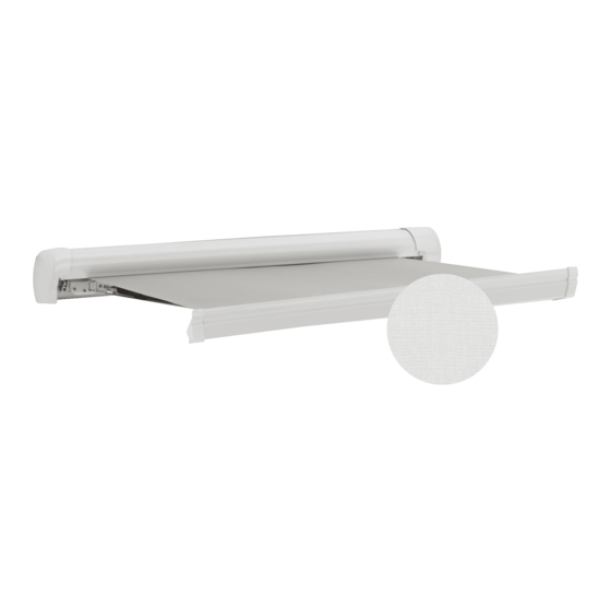
OASIS ELITE
975 SERIES
AUTOMATIC RV DOOR
AWNING SYSTEM
975XX48.XX0(#), 975XX48.XX0(#)L,
975XX56.XX0(#), 975XX56.XX0(#)L,
975XX60.XX0(#), 975XX60.XX0(#)L
Read these instructions carefully. These
instructions MUST stay with this product.
USA
SERVICE OFFICE
Dometic Corporation
1120 North Main Street
Elkhart, IN 46514
RECORD THIS INFORMATION FOR FUTURE
REFERENCE:
Model Number
Serial Number
Date Purchased
Retailer / Qualified Installer
MODEL
CANADA
Dometic Corporation
46 Zatonski, Unit 3
Brantford, ON N3T 5L8
CANADA
SERVICE CENTER &
DEALER LOCATIONS
Please Visit:
www.eDometic.com
Advertisement
Table of Contents

Related Manuals for Dometic OASIS ELITE 975 Series


Summary of Contents for Dometic OASIS ELITE 975 Series
- Page 1 REVISION B DEALER LOCATIONS SERVICE OFFICE Dometic Corporation Form No. 3310396.043 09/16 Dometic Corporation 46 Zatonski, Unit 3 Please Visit: (French 3310425.040_B) 1120 North Main Street Brantford, ON N3T 5L8 www.eDometic.com ©2016 Dometic Corporation Elkhart, IN 46514 CANADA LaGrange, IN 46761...
-
Page 2: Table Of Contents
INTRODUCTION These instructions apply to the Oasis Elite 975 series awnings (hereinafter referred to as “door awning”, “awning,” or “prod- uct”). It is designed for use over RV entry doors. This awning can be installed by one person with brief help from additional personnel. -
Page 3: Document Symbols
TABLE OF CONTENTS GENERAL CARE AND USE ..............................13 A. Precautions ................................13 B. Hardware Maintenance ............................13 C. Fabric Maintenance ..............................13 D. When To Get More Help ............................14 APPENDIX A: ELECTRONIC CONTROL KIT WIRING ......................15 DOCUMENT SYMBOLS I ndicates additional information that is NOT related ... -
Page 4: Specifications
IMPORTANT SAFETY INSTRUCTIONS reduced physical, sensory or mental capabilities, water to pool, snow to accumulate, or heavy or lack of experience and knowledge to use this debris on awning fabric. Do NOT hang or place product, unless they have been given supervision anything on awning. -
Page 5: General Information
GENERAL INFORMATION Included Hardware 3310287.002 Electronic Control Kit (2) #10-16 X 5/8” Self-Drilling Screws This kit will require additional components and wir- #6-20 X 1/2” Square Drive Screw ing (installer supplied): * Quantity varies by length of awning rail. 350766-1 Plug (3 Position) Additional Components &... -
Page 6: Determine Awning Location
PREPARE FOR INSTALLATION Determine Awning Location 2. Allow for sufficient clearance be- tween awning fabric and entry door to accom- 1. IMPACT OR CRUSH HAZARD. modate awning pitch (slope). Make sure mounting surface on RV is flat, has Avoid location that interferes with entry door solid structural backing where fasteners pene- swing when awning is completely extended. -
Page 7: Install (Fixed / Wired) Remote Awning Switch
INSTALL ELECTRICAL KITS Wiring connections to awning motor T he ignition interlock MUST break the cir- (through outside RV wall) will be made cuit (cut power) to awning when ignition later. is ON. 3. Plug wiring harness connector into “Door Motor” Use plug connectors supplied with wiring terminal on electronic control box. -
Page 8: Install Led Light Switch (If Applicable)
INSTALL ELECTRICAL KITS Install LED Light Switch (If Applicable) A llow enough wiring length to pass through outside RV wall (hole will be drilled later) An LED light switch (installer supplied) is required for connection to awning. for awning models equipped with an LED light strip. 3. -
Page 9: Complete Installation
INSTALL AWNING c. Measure 3 5/8” above horizontal mark, and U se plug connectors supplied with wiring mark new horizontal line. harness / electronic control kit. d. Measure 11/16” to left of vertical mark, and Make sure connections will mate BLACK/ mark vertically across horizontal line for wir- WHITE wire to BLACK (or BLUE) awning ing hole location. -
Page 10: Led Light Connections (If Applicable)
INSTALL AWNING Use a grommet (installer supplied) when routing FIG. 11 wiring through RV wall. 6″ I f grommet is NOT used, use heat-shrink Awning Rail tubing where wiring will pass through RV wall. 3. ALWAYS seal wiring against weather and moisture where wiring enters RV’s [walls / roof / floor]. -
Page 11: Secure Awning For Travel
VERIFY INSTALLATION II. To adjust for more retraction (awning not a. To adjust for less extension (awning tries to fully closed), turn adjustment screw clock- over extend), turn adjustment screw counter- wise. See (FIG. 12). clockwise. See (FIG. 12). b. To adjust for more extension (awning does FIG. -
Page 12: Close Or Remove Awning (Power Failure)
OPERATION With awning fully closed, test ignition interlock 2. Disable awning for travel to service center: system: a. Close awning and unplug door motor con- a. With vehicle ignition in ON position, attempt nector from electronic control box. See sec- to open awning. -
Page 13: Remove Awning From Rv
CLOSE OR REMOVE AWNING (POWER FAILURE) D o NOT connect to door motor wiring har- 3. Remove the #6 X 1/2” TEK screws securing aw- ning bracket to awning rail. See (FIG. 11). ness. Match wire lead colors to awning motor 4. -
Page 14: When To Get More Help
A pply a very small dab of VLP (Vinyl Liquid rosive cleaners, mildew removers, or hard Patch) on tip of cotton swab. bristle brushes on awning fabric. V LP is available from Dometic Cor- Liberally drench open awning fabric with poration. Reference... -
Page 15: Appendix A: Electronic Control Kit Wiring
APPENDIX A: ELECTRONIC CONTROL KIT WIRING KITS: 3310287.002 & 3310287.010 Socket 350689-1 350547-1 (18-24 AWG) (14-20 AWG) 1 2 3 Plug Plug Plug 350766-1 350777-1 350777-1 Plug Plug Plug Plug Plug Plug 350766-1 350766-1 350766-1 350777-1 350777-1 350779-1 1 2 3 1 2 3 1 2 3 1 2 3 4...