Table of Contents
Advertisement
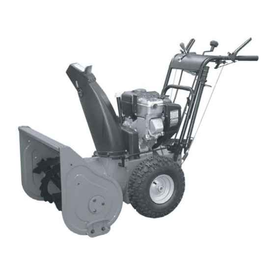
OPERATOR'S
MANUAL
Intermediate
Snowthrower Models
555 Models
Mfg. No.
Description
1694587
555M, 5HP, Manual Start
1694595
555M, 5HP, Manual Start (CE)
85665
I5225, 5HP, Manual Start
80494
EI5225, 5HP, Manual Start (CE)
7555 Models
Mfg. No.
Description
1694836
7555M, 7.5HP, Manual Start
1694837
7555EX, 7.5HP, Manual Start (CE)
7800000
I75225, 7.5HP, Manual Start
7800001
EI75225, 7.5HP, Manual Start (CE)
860 Models
Mfg. No.
Description
85666
I8245E, 8HP OHV, Electric Start
80495
EI8245, 8HP OHV, Manual Start (CE)
1694588
860E, 8HP OHV, Electric Start
1694596
860M, 8HP OHV, Manual Start (CE)
8560 Models
Mfg. No.
Description
7800017
I85245E, 8.5HP OHV, Electric Start
7800018
EI85245, 8.5HP OHV, Manual Start (CE)
1694845
8560EI, 8.5HP OHV, Electric Start
1694846
8560EX, 8.5HP OHV, Manual Start (CE)
7100195
Revision 00
Rev. Date 6/20/2005
TP 100-5065-IR-IS-N
Advertisement
Table of Contents

Related Manuals for Snapper 860


Summary of Contents for Snapper 860
- Page 1 7555M, 7.5HP, Manual Start 1694837 7555EX, 7.5HP, Manual Start (CE) 7800000 I75225, 7.5HP, Manual Start 7800001 EI75225, 7.5HP, Manual Start (CE) 860 Models Mfg. No. Description 85666 I8245E, 8HP OHV, Electric Start 80495 EI8245, 8HP OHV, Manual Start (CE) 1694588...
-
Page 2: Table Of Contents
Safety Rules & Information Training ...2 Preparation ...2 Operation ...2 Children...3 Clearing a Clogged Discharge Chute ...3 Service, Maintenance and Storage ...3 Emissions...3 Identifications Numbers ...5 Decals ...6 Safety Icons ...7 Features, Controls, & Operation Control Locations ...8 Starting Controls ...10 Ground Speed Controls ...11 Auger Control ...11 Deflector Controls ...11... -
Page 3: Safety Rules & Information
Safety Rules & Information This machine is capable to amputating hands and feet and throwing objects. Read these safety rules and follow them closely. Failure to obey these rules could result in loss of control of unit, severe personal injury or death to you, or bystanders, or damage to property or equipment. -
Page 4: Children
21. Keep in mind the operator is responsible for acci- dents occurring to other people or property. 22. Data indicates that operators, age 60 years and above, are involved in a large percentage of power equipment-related injuries. These operators should evaluate their ability to operate the unit safely enough to protect themselves and others from injury. -
Page 6: Identifications Numbers
North American / CE Models CE Models (only) Identification Numbers When contacting your authorized dealer for replace- ment parts, service, or information you MUST have these numbers. Record your model name/number, manufacturer’s identi- fication numbers, and engine serial numbers in the space provided for easy access. -
Page 7: Decals
Safety Decals GENERAL This unit has been designed and manufactured to pro- vide you with the safety and reliability you would expect from an industry leader in outdoor power equipment manufacturing. Although reading this manual and safety instructions it contains will provide you with the necessary basic knowl- edge to operate this equipment safely and effectively, we have placed several safety labels on the unit to remind you of this important information while you are operating... -
Page 8: Safety Icons
Warning: Read Operator’s Manual. Read and understand the Operator’s Manual before using this machine. Danger: Thrown Objects. This machine is capable of throwing objects and debris. Keep bystanders away. Warning: Remove Key Before Servicing. Remove the key, disconnect spark plug wire, and consult technical litera- ture before performing repairs or maintenance. -
Page 9: Features, Controls, & Operation
Features, Controls, & Operation Please take a moment ALL MODELS and familiarize yourself with the name, location, and function of these controls so that you will better understand the safety and operating instructions provided in this manual. TECUMSEH MODELS 1,2.. BRIGGS &... -
Page 10: Control Locations
CONTROL LOCATIONS The information below briefly describes the function of individual controls. Starting, stopping, and driving require the combined use of several controls applied in specific sequences. To learn what combination and sequence of controls to use for various tasks see the OPERATION section. Speed Selector 1,2.. -
Page 11: Starting Controls
Engine Controls STARTING CONTROLS See Figures 1 & 2 for the following instructions. Units with Optional Electric Start A. Electric Start Button (North American Models)- The electric start button (A) activates an electric starter mounted to the engine, eliminating the need to pull the starter handle. -
Page 12: Ground Speed Controls
GROUND SPEED CONTROLS A. Speed Selector - This lever (A, Figures 3 & 4) is used to set the ground speed of the snowthrower. The snowthrower has five forward speeds, 1–5, and two reverse speeds, 1–2. No neutral position or gate is required, since the traction drive design automati- cally provides "neutral"... -
Page 13: General Operation
Operation GENERAL OPERATION CHECKS BEFORE EACH START-UP 1. Make sure all safety guards are in place and all nuts, bolts and clips are secure. 2. Check to make sure that the clean-out tool is attached to the handle on the machine. Do not oper- ate the machine without the clean-out tool properly stored on the handle. -
Page 14: Starting The Engine
STARTING THE ENGINE 1. Turn the fuel valve (B, Figure 5 & 6) to the ON posi- tion. 2. Insert the engine key (F) into the engine key slot and push fully in to the RUN position. 3. Move the throttle lever (E) fully up to the FAST posi- tion. -
Page 15: Operating The Snowthrower
Operation OPERATING THE SNOWTHROWER 1. Rotate the discharge chute to the desired direction. 2. Set the speed selector to the desired forward speed. 3. Fully press and hold the auger control (C, Figure 7) on the right-hand grip to begin auger rotation. To dis- engage the auger, completely release the lever. -
Page 16: Deflector
DEFLECTOR The distance of the discharged snow is mainly controlled by the position of the deflector (Figure 9). (Engine speed also affects distance of discharge. Always operate at FULL throttle.) The more the deflector is tilted UP, the farther snow will be thrown. -
Page 17: Free Wheeling And Traction Drive Lock
Operation FREE-WHEELING AND TRACTION DRIVE LOCK For easy turning when pushing the snowthrower, you can disengage the traction drive at one or both wheels by using the traction lock pins (See Figures 11 & 12). 1. Turn the unit off, remove the engine key, and discon- nect the spark plug wire. -
Page 18: Regular Maintenance
MAINTENANCE SCHEDULE MAINTENANCE REQUIRED Check auger gear case lubrication.** Lubricate snowthrower. Check tire pressure. Change engine oil.* Clean or replace spark plug. Check drive linkage/belt tension. Lubricate Axle Shafts. Check / Lubricate Free-Hand Linkage. Lubricate Auger Shaft. *** * Change original oil after two hours of operation. ** Check oil level each fall and spring. -
Page 19: Lubrication
Maintenance LUBRICATION IMPORTANT NOTE It is very important that grease fittings on the auger shaft are lubricated regularly. If auger rusts to shaft, damage to worm gear may occur if shear pins do not break. To prevent wheels rusting to axles, it is also necessary to remove the wheels and grease the axles regularly. -
Page 20: Check / Lubricate Free-Hand Linkage
LUBRICATION CHECK / LUBRICATE FREE-HAND LINKAGE Check the function of the Free-Hand controls: the con- trols should function as described in the CONTROLS section. It is critical for the safe operation of the unit that the controls disengage when released. If the controls do not function properly, lubricate them. -
Page 21: Troubleshooting, Adjustment, & Service Troubleshooting
Troubleshooting, Adjustment, & Service TROUBLESHOOTING This section provides troubleshooting and service instructions. Locate the problem and check the possible cause/remedy in the order listed. Also, refer to the engine manufacturer’s Owner’s Manual for additional information. For problems not covered here, contact your local deal- PROBLEM Engine fails to start. - Page 22 PROBLEM Auger rotates, but snow is not thrown far enough Scraper bar does not clean hard surface. Scraper bar picks up and throws stones on gravel drive. Poor traction Auger does not stop when auger lever is released Snowthrower does not stop when drive lever is released Snowthrower does not drive when drive lever is engaged.
-
Page 23: Speed Selector Pivot Adjustment
Adjustments SPEED SELECTOR PIVOT ADJUSTMENT The speed selector is factory set for optimal performance at each forward and reverse speed setting. However, if drive system components have been replaced, adjust- ment may be necessary. Adjust as follows: 1. Move the ground speed control (A, Figure 19) fully forward. -
Page 24: Discharge Chute Worm Assy. Adjustment
MANUAL DISCHARGE CHUTE CONTROL LINKAGE ADJUSTMENT Pinion Gear Adjustment If the discharge chute is difficult to operate, first lubricate the pinion gear (A, Figure 21) and ring gear (F). If it is still difficult to operate, adjust as follows: NOTE: If the discharge chute will not stay in position, adjust the pinion gear (A) closer to the ring gear (F). -
Page 25: Auger Drive Clutch Cable Adjustment
Adjustments AUGER DRIVE CLUTCH CABLE ADJUSTMENT The auger drive clutch cable should be adjusted so that there is no slack in the cable when moved slightly from side to side. To adjust tension on the cable: 1. Loosen adjustment hex nut (Figure 23) by holding the adjusting flats and turning adjustment hex nut . - Page 26 DRIVE BELT ADJUSTMENT If the auger drive slips (auger slows or doesn't rotate nor- mally while blowing snow), or stays engaged when the control is disengaged — and the auger clutch cable has been properly adjusted — the auger drive belt may be out of adjustment.
-
Page 27: Drive Belt Replacement
Adjustments & Service DRIVE BELT ADJUSTMENT Adjusting Auger Belt Guide 1. With the auger control still fully depressed, adjust the auger belt guide(s) so that there is a 1/64” gap (1/32” Maximum) between the guide and the belt (Figures 28, 28a), making certain the guide is NOT putting pressure on the belt. -
Page 28: Auger Drive Belt Replacement
DRIVE BELT REPLACEMENT Traction Drive Belt Replacement (Cont.) 5. Reverse the procedure to install the new belt. Be sure there are no twists in the belt, and that the belt is properly seated in the pulley grooves. 6. Replace the belt cover. 7. -
Page 29: Roller Chain Replacement
Service ROLLER CHAIN REPLACEMENT NOTE: This procedure does not apply to models that use an “endless” chain. 1. Remove gas from fuel tank and run engine until it stops running from lack of fuel. 2. Disconnect spark plug wire and fasten it away from the spark plug. -
Page 30: Specifications
3600 8560EX 3600 CHASSIS: Wheels Spout Rotation Impeller Drive System DIMENSIONS Effective Clearing Width -555, I5225, 7555, I75225 -860, I8245, 8560, I85245 Length -555, I5225, 7555, I75225, 860, I8245, 8560, I85245 Height -555, I5225, 7555, I75225, 860, I8245, 8560, I85245... -
Page 31: Replacement Parts & Accessories
Replacement Parts & Accessories Section TopicXXXX REPLACEMENT PARTS Replacement parts are available from your authorized dealer. Always use genuine Simplicity / Snapper Service Parts. MAINTENANCE ITEMS Many convenient and helpful service and maintenance items are available from your authorized dealer. Some of... - Page 32 M A N U F A C T U R I N G , I N C . 500 N Spring Street / PO Box 997 Port Washington, WI 53074-0997 www.simplicitymfg.com © Copyright 2005, Simplicity Manufacturing, Inc. All Rights Reserved. Printed in USA.