Denon RCD-M38 Service Manual
Stero cd receiver
Hide thumbs
Also See for RCD-M38:
- User manual ,
- Owner's manual (84 pages) ,
- Manual del usuario (37 pages)
Table of Contents
Advertisement
e
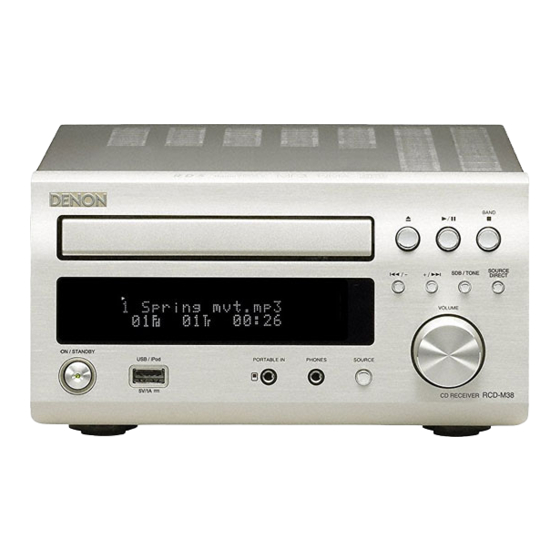
RCD-M38
RCD-M38DAB
D-M38S
• For purposes of improvement, specifi cations and design are subject to change without notice.
• Please use this service manual with referring to the operating instructions without fail.
• Some illustrations using in this service manual are slightly different from the actual set.
S0105-1V03DM/DG1007
SERVICE MANUAL
MODEL
STEREO CD RECEIVER
Copyright 2010 D&M Holdings Inc. All rights reserved.
WARNING: Violators will be prosecuted to the maximum extent possible.
JP
E3
E2
e
D&M Holdings Inc.
Ver. 3
Please refer to the
MODIFICATION NOTICE.
EK
EA
E1
E1K E1C
Advertisement
Table of Contents

Related Manuals for Denon RCD-M38


Summary of Contents for Denon RCD-M38
- Page 1 Please refer to the MODIFICATION NOTICE. SERVICE MANUAL MODEL E1K E1C RCD-M38 RCD-M38DAB D-M38S STEREO CD RECEIVER • For purposes of improvement, specifi cations and design are subject to change without notice. • Please use this service manual with referring to the operating instructions without fail.
-
Page 2: Safety Precautions
SAFETY PRECAUTIONS The following check should be performed for the continued protection of the customer and service technician. LEAKAGE CURRENT CHECK Before returning the unit to the customer, make sure you make either (1) a leakage current check or (2) a line to chassis resistance check. -
Page 3: Note For Schematic Diagram
NOTE FOR SCHEMATIC DIAGRAM WARNING: Parts marked with this symbol z have critical characteristics. Use ONLY replacement parts recommended by the manufacture CAUTION: Before returning the unit to the customer, make sure you make either (1) a leakage current check or (2) a line to chassis resistance check. If the leakage current exceeds 0.5 milliamps, or if the resistance from chassis to either side of the power cord is less than 460 kohms, the unit is defective. -
Page 4: Warning And Laser Safety Instructions
WARNING AND LASER SAFETY INSTRUCTIONS WARNING WAARSCHUWING All ICs and many other semi-conductors are Alle IC’s en vele andere halfgeleiders zijn susceptible to electrostatic discharges (ESD). gevoelig voor elektrostatische ontladingen Careless handling during repair can reduce (ESD). life drastically. Onzorgvuldig behandelen tijdens reparatie When repairing, make sure that you are kan de levensduur drastisch doen connected with the same potential as the... -
Page 5: System Configuration
SYSTEM CONFIGURATION • RCD-M38 • D-M38S (RCD-M38/SC-M37) • RCD-M38DAB SC-M37 : Refer to the service manual of SC-M37. RCD-M38 SC-M37 SPECIFICATIONS n Audio section n Clock/Timer section Power amplifer Clock method: Crystal oscillator (Within 1 – 2 minutes per month)) Rated output:... -
Page 6: Caution In Servicing
Refer to "MEASURING METHOD AND WAVEFORMS". Service Jigs When you repair the printing board, you can use the following JIG (Extension cable kit). Please order to Denon Official Service Distributor in your region if necessary. 943309004570M : DATA UPDATE KIT :... - Page 7 DISASSEMBLY • Disassemble in order of the arrow of the figure of following flow. • In the case of the re-assembling, assemble it in order of the reverse of the following flow. • In the case of the re-assembling, observe "attention of assembling" it. • I f wire bundles are untied or moved to perform adjustment or parts replacement etc., be sure to rearrange them neatly as they were originally bundled or placed afterward. Otherwise, incorrect arrangement can be a cause of noise generation. TOP CABINET DOOR REAR PANEL SUB ASSY Refer to "DISASSEMBLY Refer to "DISASSEMBLY 6. REAR PANEL SUB ASSY" 1. DOOR" and "EXPLODED VIEW" and "EXPLODED VIEW" DOOR SUB TRANS UNIT (Ref. No. of EXPLODED VIEW : P9) (Ref. No. of EXPLODED VIEW : C6) INPUT P.W.B UNIT ASSY (Ref. No. of EXPLODED VIEW : C8) DAB MODULE (for EK model) FRONT PANEL SUB ASSY...
- Page 8 About the photos used for descriptions in the DISASSEMBLY" section. • T he direction from which the photographs used herein were photographed is indicated at "Direction of photograph: ***" at the left of the respective photographs. • Refer to the table below for a description of the direction in which the photos were taken. • Photographs for which no direction is indicated were taken from above the product. • The photograph is RCD-M38 EK model. The viewpoint of each photograph Direction of photograph: B (Photografy direction) Front side [View from above] Direction of photograph: D...
- Page 9 (2) Open the CD tray by turning the Drive gear clockwise. Drive gear CD tray (3) Detach the DOOR. Direction of photograph: B DOOR...
- Page 10 2. FRONT PANEL SUB ASSY Proceeding : TOP CABINET DOOR FRONT PANEL SUB ASSY → → (1) Remove the screws. View from bottom (2) Disconnect the connector wire and FFC cable, then remove the screws. Direction of Direction of photograph: C photograph: D FFC cable CN82 Outside of CD macha foot (3) Disconnect the connector wire. CN83 Direction of photograph: B FRONT PANEL SUB ASSY...
-
Page 11: Cd Mechanism Ass'y
3. CD MECHA Proceeding : TOP CABINET DOOR FRONT PANEL SUB ASSY → → CD MECHANISM ASS'Y → (1) Remove the screws. (2) Laser short-circuit in Pick-up of CD MECHANISM ASS'Y, then disconnect the connector wires and FFC cable. Soldering place CD MECHANISM ASS'Y Direction of photograph: B CN26 CN25 FFC cable Protective soldering place for laser diode. - Page 12 4. MCU PCB UNIT ASSY Proceeding : TOP CABINET DOOR FRONT PANEL SUB ASSY → → CD MECHANISM ASS'Y MCB PCB UNIT ASSY → → (1) Remove the screws. Direction of photograph: B View from bottom (2) Cut the wire clamp band, then disconnect the connector wires and FFC cable. Remove the screws. CN12 CN96 CN98 Direction of photograph: B FFC cable CN71...
-
Page 13: Heat Sink Sub Assy
5. HEAT SINK SUB ASSY Proceeding : TOP CABINET DOOR FRONT PANEL SUB ASSY → → CD MECHANISM ASS'Y HEAT SINK SUB ASSY → → (1) Remove the screws. Direction of photograph: B View from bottom (2) Cut the wire clamp band, then disconnect the connector wires. Remove the screws. Direction of photograph: C CN95 CN72 HEAT SINK SUB ASSY... - Page 14 6. REAR PANEL SUB ASSY Proceeding : TOP CABINET REAR PANEL SUB ASSY → (1) Remove the screws. View from bottom (2) Disconnect the connector wires. Direction of photograph: D CN98 CN96 (3) Disconnect the connector wires and FFC cable, then remove the screws. CN72 FFC cable CN93 CN12 (4) Remove the screws. Direction of photograph: A...
- Page 15 (5) Disconnect the FFC cable. Direction of photograph: B FFC cable Please refer to "EXPLODED VIEW" for the disassembly method of each PCB included in REAR PANEL SUB ASSY. 7. SPK UNIT Proceeding : TOP CABINET REAR PANEL SUB ASSY SPK UNIT → → Please refer to "EXPLODED VIEW" for the disassembly method of SPK UNIT. 8. TRANS Proceeding : TOP CABINET REAR PANEL SUB ASSY SPK UNIT TRANS → → →...
- Page 16 DISASSEMBLY OF MECHANIC (Follow the procedure below in reverse order when reassembling.) Caution : The optical pickup can damaged by sassily by static electricity charged on human body. Take necessary anti-static measures when repairing around the optical pickup. 1. Chucking plate (1) Remove 2 top screws, then detach the Chucking plate.
-
Page 17: Note Handling And Replacement Of The Laser Pick-Up
NOTE HANDLING AND REPLACEMENT OF THE LASER PICK-UP 1. Protection of the LD Short a part of the LD circuit by soldering. After connection to a circuit, remove the short solder. 2. Precautions when handling the laser CD mechanism • Handle the laser pick-up so that it is not exposed to dust. • Do not leave the laser pick-up bare. Be sure to cover it. -
Page 18: Service Mode
SERVICE MODE 1. Version Display Mode (1) Plug AC cord into power outlet while pressing ON/STANDBY and DIRECT button same time on Main Unit. (2) Press the "SDB/TONE" button to the display the 2nd item information on the Display. 【Main µ-com Ver.】→【USB µ-com Ver.】→【iPod Dock Ver.(Connecting Dock)】→【Main µ-com Ver.】→・・・ 【Main µ-com Ver.】... -
Page 19: Disc Loading
CD test mode (1) Plug AC cord into power outlet while pressing ON/STANDBY and SOURCE button same time on Main Unit. " 1 3 " T E S T M O D E ( 1 , 3 flashing) (2) Move the slide to the initially set position (10 mm towards the outside from the innermost position). (3) Check by performing key input. - Page 20 4.3 Pickup movement (1) In the stop mode, pickup moves in REV (inwards) or FWD (outwards) direction when 8 / - or + / 9 button pressed. (2) When 8 / - button pressed, move to stop operation after detection that inner switch has turned on. (3) Pickup movement stops when button released.
- Page 21 4.7 Laser current is display (1) When the 2 button is pressed for over 1 second while the RCD-M38 is in the stop mode(Display of "4. CD test mode (1)"), the laser turns on and the laser current is measured.
- Page 22 5. CD heat run mode (1) Plug AC cord into power outlet while pressing ON/STANDBY and SDB/TONE button same time on Main Unit. (Be sure to insert the CD before this operation) 1 1 Tr 4 2 : 5 2 (...
-
Page 23: Error Display
【When TOC is read】 R E A D I N G ( 1 , 3 lit) 5.3 Error display E X - X X ( 1 , 3 lit / X-XX:Error cord) Error code E1-00 Disc cannot be detected E1-01 Tracking offset adjustment not possible E1-02 Focus offset adjustment not possible E2-00... -
Page 24: Accumulated Laser On Time Display Mode
6. Accumulated laser on time display mode (1) Plug AC cord into power outlet while pressing ON/STANDBY and 2 button same time on Main Unit. X X X X X h o u r L A S E R T I M E • The laser drive times are added and the result is displayed. -
Page 25: Version Upgrade Procedure Of Firmware
VERSION UPGRADE PROCEDURE OF FIRMWARE 1. ABOUT REPLACE THE MICROPROCESSOR WITH A NEW ONE When replaced of the U-PRO (Microprocessor) or the Flash ROM, confirm contents of the following. After PWB Name Ref. No. Description Remark replaced IC11 TMPM330FYFG for E3,E2P model IC11 CVIT5CN5 for EK model... -
Page 26: Necessary Equipment
• Windows PC (OS: Windows2000 or WindowsXP) with Serial port. • RS-232C Dsub-9 pin cable (female to female/straight type) • DATA UPDATE KIT for M-CR502/RCD-M38 (part no : 943309004570M) • Update tool (FlashProg.exe, other files and folders in Flash Programmer folder) •... - Page 27 (4) Double click the "Flash Programmer" folder. (5) Double click FlashProg_b35.exe, and launch the Flash Programmer. NOTE : When a Flash Programmer does not launch even if double-clicked FlashProg_b35.exe, please refer to "2.3. When a Flash Programmer did not launch".
- Page 28 (6) The following dialog box appears several seconds later after the Flash Programmer launch. Click OK. NOTE : Since Flash Programmer communicates with the unit automatically, the above dialog box appears when it fails in communication. (7) Click the Setup in the menu bar and select the Device.
- Page 29 (8) Choose the TMP92FD28 in the Device, and choose the 900/H1 in the Series. And click Object File tab. (9) Click Browse.
- Page 30 (10) Choose the Motorola S Format(*.s16,*.s24, *.s32) in Files of type. Choose the RCD-M38DAB_100430-00-USB.s32, and click Open. (11) Click Communication tab.
- Page 31 (12) Choose the Serial port number in the COM Port. Check the Data Rate Auto. Input the 9.00 in the Clock. And Click OK. (13) Click the File in the menu bar and select the Exit.
- Page 32 (14) Disconnect the mains cord from the unit. (15) Connect the RS-232C on the DATA UPDATE KIT and the Serial Port of windows PC with RS-232C cable. Set the slide switch (SW12) to "MCU DOWNLOAD". (16) Connect the connective wire (1 pin is lower in a picture) to the bottom chassis of the unit from DATA UPDATE KIT. Caution : A connector pin has the connection direction.
- Page 33 (21) Click OK. (22) Click P (Program) to start update. (23) Software is written into the microprocessor. The writing of software takes about 30 seconds.
- Page 34 (24) If the software is updated successfully, a dialog box saying "R006: Programming completed successfully." appears. Click OK. (25) Click the File in the menu bar and select the Exit. (26) OPress the ON/STANDBY button to turn off the unit. (27) Disconnect the mains cord from the unit, and then disconnect the connective wire of DATA UPDATE KIT from the unit.
- Page 35 2.3. When a Flash Programmer did not launch (1) Open the FlashProg.ini in the Flash Programmer folder by text editor. (EX.: Notepad, etc) (2) Delete the text "OpenFile=C:\...(your PC setting)...\???.s32".
- Page 36 (3) Save the FlashProg.ini.
- Page 37 (4) Close the text editor. (5) Probably you can launch the Flash Programmer. Go to the "Procedure of the UDSB CPU's Update "step 5.
-
Page 38: Troubleshooting
TROUBLE SHOOTING 1. VFD dosen't light Check Power Supply Voltages for System µ-com. Check Soldering. MCU_CD B'D • [CN96] : 1pin • ST+3.9V, [CN96] : 1pin • SUB TRANS B'D • [D204] cathode Check Reset signal for System µ-com. MCU_CD B'D Check Soldering. • [IC11] : 82pin RESET • [IC11] on MCU_CD B'D "H" level O.K.? Check Oscillation waveform. MCU_CD_B'D Check Soldering. • [IC11] : 72pin • [X101] on MCU_CD B'D 10MHz OK? Check Power On Signal. Check Soldering. -
Page 39: No Sound,Noise Generated
2. No Sound,Noise generated 2.1. CD PLAY Check Soldering. Check Power Supply Voltages for CD. • MCU_CD B'D [CN98] : 1,3pin MCU_CD B'D +8VM, USB+9V • [CN98] : 1pin +8VM • POWER B'D • [CN98] : 5pin USB+9V Check Parts • [IC51] : 1pin USB+5V • [IC71] Check Soldering. Check Power Supply Voltages for CD. • [IC51] on MCU_CD B'D MCU_CD B'D • [IC52] on MCU_CD B'D • D+3.3V [IC51 ]: 2pi 3.3V OK? Check Parts • +1.5V [IC52] : 2pi 1.5V OK? • [IC51],[IC52] Check Power Supply Voltages for DAC. Check Soldering. INPUT B'D • [CN72] : 9pin SW+5V • [IC15] :14pin VDD 5V OK? • POWER B'D Check Reset signal for CD. MCU_CD B'D Check Soldering. - Page 40 Check Soldering. Check Digital Audio Data and Clock for DAC. • [IC16] on MCU_CD B'D INPUT B'D • [WN12] : 2,3,4pin on MCU_CD B'D • [IC15] : 2,3,4pin BICK,SDTI,LRCK BIK,STI,LRK • [WF12] on INPUT B'D Check Analog Audio Data output from DAC. Check Soldering. INPUT B'D • [IC15] : 9,10,11,12pin on INPUT B'D • [IC15] : 9,10,11,12pin on INPUT B'D • [IC17] on INPUT B'D. • [IC17] output 1,7pin Check Analog Audio Data input for FUNCTION IC. INPUT B'D Check Soldering. • [IC11] input 23,24pin • [IC11] on INPUT B'D F_CD_USB_L,FCD_USB_R Check Soldering. Check control signal for FUNCTION IC. • [IC11] on MCU_CD B'D INPUT B'D • [WF11] : 6,7,8pin on INPUT B'D • [IC11] : 29,30,31pin V_DATA,V_CLK_VCE D_DATA,C_CLK,V_CE • [WN11] on MCU_CD B'D Check Analog Audio Data output from FUNCTION & PRE AMP. Check Soldering. • [IC11] : 49, 50pin Lout,Rout • [IC11] on INPUT B'D • [IC12] : 1,7 pin • [IC12] on INPUT B'D Check Soldering. Check audio function mute signal. • [Q106],[112] on INPUT B'D INPUT B'D • [WF11] : 10pin F_MU on INPUT B'D • [Q112(B)] : "L" level O.K.?
- Page 41 2.2. AM/FM TUNER-in Check Soldering. Check Power Supply Voltages for PREAMP & POWER AMP. • [CN72] : 1,5pin +12V,-12V on INPUT B'D • INPUT B'D : +12V,-12V • [CN97] : 5,6,8,9pin -22.8V,+22.8V on AMP B'D • AMP B'D : +22.8V,-22.8V • POWER B'D • SPEAKER B'D Check Soldering. Check Power Supply Voltages for AM/FM TUNER. • [CN98] : 9pin +12V on MCU_CD B'D MCU_CD B'D • POWER B'D • [WN21] : 4pin +9V Check Parts • [CN98] : 9pin +12V • [IC17] Check Analog Audio Data output from TUNER PACK. Check Soldering. MCU_CD B'D • [WN21] : 7,5 pin TU_L,TU_R on MCU_CD B'D • [TUNER PACK] output and [WN21] : 7,5pin TU_L, TU_R • [WN11] : 12,14pin TU_R,TU_L on MCU_CD_B'D INPUT B'D • [WF11] : 12,14pin F_TU_R,F_TU_L on INPUT B'D • [IC11] : 25,26pin • [C122],[CN123] on INPUT B'D Check Digital Audio Data output from FUNCTION IC. Check Soldering. INPUT B'D • [IC11] on INPUT B'D • [IC11] : 49,50pin LOUT,ROUT to CD PLAY z Mark 2.3.
- Page 42 2.4. DAB TUNER-in (EK model) Check Soldering. Check Power Supply Voltages for DAB TUNER UNIT. • [CN72] : 9pin SW+5V on INPUT B'D INPUT B'D • POWER B'D • SW+5V • [IC18],[IC19] on INPUT B'D • DAB+3.3V (CN11 2pin) Check Part • DAB+1.5V (CN11 1pin) • [IC18],[IC19] on INPUT B'D Check controll signal for DAB TUNER. Check Soldering. INPUT B'D • [WF11] : 2,3pin on INPUT B'D • [CN11] : 15,16pin • [WN11] on MCU_CD B'D DAB_DO • [IC11] on MCU_CD B'D DAB_DI Check Analogl Audio Data output from DAB TUNER. INPUT B'D Check Soldering. • [DAB TUNER] output • [CN11] on INPUT B'D [CN11] : 29,30pin DAB_L,DAB_R Check Audio Data intput from FUNCTION IC. Check Soldering. INPUT B'D • [IC11] on INPUT B'D • [I11] : 27,28pin DAB_L,BAD_R • [C124],[C125] Check Audio Data intput from FUNCTION IC. Check Soldering. INPUT B'D • [IC11] on INPUT B'D • [I11] : 49.50pin LOUT,ROUT...
- Page 43 2.6. iPod PLAY Check Soldering. Check iPod Dock control signal • [JK13] on INPUT B'D INPUT B'D • [WF11] : 4,5pin IPOD_TX,IPOD_RX on INPUT B'D • [JK13] • [WN11] on MCU_CD B'D IPOD_RX,IPOD_TX • [IC11] on MCU_CD B'D Check Analog signal output from iPod Dock Check Soldering. INPUT B'D • [JK11] on INPUT B'D • [JK11] AUX1 in L,R • [IC11] on INPUT B'D • [IC11] :13,14pin AUX1_L,AUX1_R Check Audio Data output from FUNCTION IC Check Soldering. INPUT B'D • [IC11] on INPUT B'D • [IC11] : 49,50pin LOUT,ROUT to CD PLAY z Mark...
-
Page 44: Measuring Method And Waveforms
MEASURING METHOD AND WAVEFORMS To check the waveforms, the GND (-) probe of the oscilloscope to specified reference voltage. (Except for lnner SW, TRVSW) NOTES Measuring Disc: CD/TCD-784 CD-R/TCD-R082W CD-RW/TCD-W082W (It is better to use wires for extending between the probe and test points.) •... -
Page 45: Input Pcb : Test Point
2. INPUT PCB : TEST POINT Foil side Symbol Symbol Reference voltage RFEQO Ⓐ VC : q ~ i Ⓑ CN26(4) MGND : o ~ Q2 CN83(5) DGND : Q3 , Q4 Ⓒ R202(0Ω) Ⓓ WF12(9) DGND : Q5 ~ Q7 R203(0Ω) R243(0Ω) R241(0Ω) - Page 46 3. WAVEFORMS 1. DISC PLAY RF WAVEFORM (EYE-PATTERN) 2. DISC DETECTION 2.1 CD(TCD784) DETECTION 1.1 CD(TCD784) PLAY 1V/div w RFO 500mV/div e FEI 1V/div r FOO q RFEQO 1V/div t TEI 1V/div y TRO 500mV/div u FMO 1V/div i DMO 2.2 CD-R (TCDR082W) DETECTION 1.2 CD-R (TCDR082W) PLAY 1V/div...
-
Page 47: Focus Adjustment
3. TOC READ 4. FOCUS ADJUSTMENT 4.1 CD(TCD784) FOCUS ADJUSTMENT 3.1 CD(TCD784) READ 1V/div w RFO 500mV/div e FEI 1V/div r FOO 1V/div t TEI 1V/div y TRO 500mV/div u FMO 1V/div i DMO 4.2 CD-R (TCDR082W) FOCUS ADJUSTMENT 3.2 CD-R (TCDR082W) READ w RFO 1V/div e FEI... - Page 48 5. CD Playback Q5 L RCK Q6 B ICK Q7 S DTI STANDARD GND WF12 (9) 6. USB playback Q3 D + Q4 D - STANDARD GND CN83 (5) 7. LOADER OPEN-CLOSE o OPSW Q0 F CLSW Q2 L OAD- Q1 L OAD+ OPEN CLOSE...
-
Page 49: Block Diagram
BLOCK DIAGRAM FL DISPLAY FUTABA(16-ST-103GINK) MOTOR OPEN/CLOSE DRIVER MECHA CONTROL LODING+/- INTERPION 10MHz 32.768KHz IP4001CRL XOUT XOUT PWR_ON FL_ON DC 21V EEPROM MAIN JP ONLY DC 14.5V CD DSP CONTROL DATA & CLOCK OPTICAL OUT AC 3.5V TRANS TOSHIBA TOSHIBA TC94A92FG DC+9V AUDIO DAC... -
Page 50: Current Block Diagram
CURRENT BLOCK DIAGRAM +8VM Reg 305mA +12V Reg +9V Reg 20mA 80mA 200mA(MAX) +8V Reg NJW1153FG1 TUNER SP/HP CD MOTOR OP AMP FUN+VOL IC MODULE RELAY DRIVER 14.5V 0.45A -8V Reg 20mA 44mA -12V Reg 69mA TWOFOLD VOLTAGE AC RELAY TRANS 40mA DC 6.5V... -
Page 51: Laevel Diagram
LAEVEL DIAGRAM DAB UNIT NJW1153 NJM2068 STK4142 FUNCTION SWITCH TUNER MASTER TONE POWER AMP PACK VOLUME CONTROL TUNER Buffer Buffer Buffer MUTE RELAY CD UNIT Buffer CD/USB SP OUT AK4385 RELAY HP OUT Portable In LINE1(Dock) IN LINE2 IN MUTE LINE2 OUT SUBWOOFER SP OUT... -
Page 52: Wiring Diagram
WIRING DIAGRAM... -
Page 53: Printed Wiring Boards
PRINTED WIRING BOARDS MCU PCB (COMPONENT SIDE) INPUT PCB (COMPONENT SIDE) GUIDE PCB (COMPONENT SIDE) REGULATOR PCB (COMPONENT SIDE) 鉛フリー半田 半田付けには、鉛フリー半田 (Sn-Ag-Cu) を使用してください。 Lead-free Solder When soldering, use the Lead-free Solder (Sn-Ag-Cu). - Page 54 MCU PCB (FOIL SIDE) INPUT PCB (FOIL SIDE) GUIDE PCB (FOIL SIDE) REGULATOR PCB (FOIL SIDE) 鉛フリー半田 半田付けには、鉛フリー半田 (Sn-Ag-Cu) を使用してください。 Lead-free Solder When soldering, use the Lead-free Solder (Sn-Ag-Cu).
- Page 55 FRONT PCB (COMPONENT SIDE) SUB TRANS PCB (COMPONENT SIDE) AMP PCB (COMPONENT SIDE) SPK PCB (COMPONENT SIDE) 鉛フリー半田 半田付けには、鉛フリー半田 (Sn-Ag-Cu) を使用してください。 Lead-free Solder When soldering, use the Lead-free Solder (Sn-Ag-Cu).
- Page 56 FRONT PCB (FOIL SIDE) SUB TRANS PCB (FOIL SIDE) AMP PCB (FOIL SIDE) SPK PCB (FOIL SIDE) 鉛フリー半田 半田付けには、鉛フリー半田 (Sn-Ag-Cu) を使用してください。 Lead-free Solder When soldering, use the Lead-free Solder (Sn-Ag-Cu).
-
Page 57: Schematic Diagrams
LED_RED TEST2 R220 C231 LRCK1 RVDD3 RCD-M38DAB : T5CN5(512K) OPSW OPSW VCOI C202 2200P SLED+ SLED+ R313 LED_GREEN CD_OPEN-SW VFD_RST RCD-M38 : TMPM33OFYFG(256K) CLSW CLSW SPINDLE- R312 0.1uF R201 C201 VFD_RST CD_CLOSE-SW R122 D+3.3V VFD_DI R244 VCOF C301 VFD_DI CD_OPEN-M 0.1uF... - Page 58 SHEET 01 SHEET 01 TO CD/MCU B'D TO CD/MCU B'D WF11 WF12 SHEET 02 INPUT B'D +12V 78L08 IC14 INPUT Part D112 1SS355T IC16 HVIKIC7S66FU D114 D110 1SS355T * JPN Ver. ONLY R140 100K R144 100K R141 R145 100K 100K SW+5V R142 100K...
- Page 59 TO SUB PWR B'D SHEET 03 SHEET 02 FL81 CFL16ST103GINK CN73 RC81 HRVKSM603TH2 FRONT/POWER/AMP POWER B'D FRONT B'D +12V R831 +8VM R830 C805 100P L901 Part C806 100P R802 R803 VOUT GND Vcc +VKK C807 100P ST+3.3V C808 0.1uF C809 0.1uF L803 VFD+3.3V...
- Page 60 EXPLODED VIEW s WARNING: Parts marked with this symbol have critical characteristics. Use ONLY replacement parts recommended by the manufacturer. 印の部分は安全を維持するために重要 な部品です。従って交換時は必ず指定の 部品を使用してください。...
-
Page 61: Parts List Of Exploded View
CTB4+8FR SCREW CTW3+18JR 943412009020D VOLUME KNOB ASSY CGK1A162ZA SCREW CTB3+8JFZR 943412009010D VOLUME KNOB ASSY CGK1A162YA SCREW CTB3+10JFZR 00D1310158049 BADGE , DENON CGB1A140U DOT SCREW CTBD3+8JFZR 00D1310158052 BADGE , DENON CGB1A140T DOT SCREW CTBD3+8JFN 943402009750D FRONT PANEL (K) CKM2A196WC45 SCREW CTWD4+6FFZR... -
Page 62: Exploded View Of Cd Mechanism Unit
EXPLODED VIEW OF CD MECHANISM UNIT PARTS LIST OF CD MECHANISM UNIT s z Parts for which "nsp" is indicated on this table cannot be supplied. z The parts listed below are for maintenance only, might differ from the parts used in the unit in appearances or dimensions. Ref. -
Page 63: Packing View
PACKING VIEW D-M38S RCD-M38 SC-M37 PARTS LIST OF PACKING & ACCESSORIES zParts for which "nsp" is indicated on this table cannot be supplied. zThe parts listed below are for maintenance only, might differ from the parts used in the unit in appearances or dimensions. -
Page 64: Fcc Label
Ref. No. Part No. Part Name Remarks Q'ty 943429007990S ANT , DAB CSA1A036Z WARRANTEE CARD CQE1A224V 943611000230S CORD , POWER CJA2A107ZV 943611000210S CORD , POWER CJA2E106ZV 943611000190S CORD , POWER CJA2B108ZV BAG , POLY EK,E2 CPB1A008Z LABEL , CONTROL EK,E2 CQB1A993Z COLOR LABEL(GRAY) SPEK,SPE2... - Page 65 SEMICONDUCTORS Only major semiconductors are shown, general semiconductors etc. are omitted to list. The semiconductor which described a detailed drawing in a schematic diagram are omitted to list. 1. IC's TMP92FD28FG (MCU : IC41)
- Page 66 TMP92FD28FG Block Diagram...
- Page 67 LED blink PWR ON_BOL when update, control power on Open DVSS3A DVSS3A DVCC3A VDD3.3V MODEL OPTION PU/PD H or L RCD-M38:"LOW" / RCD-M38DAB:"HIGH" MODEL OPTION RCD-M38"LOW" / MC-R503 "HIGH" Open CP-RESET to Apple Chip (WWI) IC42(MFI341S2164) Open Open Open Open...
- Page 68 Status Pin No Port Name Port Name Note Pull-U/D init. stby Act. Open Open Open Open BOOT Open LRCK1 to Oasis (IC16) VDD3.3V Oscilator connection 9MHz output DVSS Oscilator connection 9MHz input DVCC3A VDD3.3V USB_OC USB over current detection Open USB+ USB- VDD3.3V...
- Page 69 TMPM330FYFG (for E3,E2,JP model) / T5CN5 (for EK model) (MCU : IC11)
- Page 70 TMPM330FYFG (for E3,E2,JP model) / T5CN5 (for EK model) Block Diagram TMPM330FYFG (for E3,E2,JP model) / T5CN5 (for EK model) Terminal Function Status Port Name Port Name Pull-up/ Note init. stby Act. down 1 PD6 AMP_PRT Pull-up AMP protect detect 2 AN11 POWER_PROT I Pull-down...
- Page 71 Status Port Name Port Name Pull-up/ Note init. stby Act. down 20 TXD0 USB_TX/UPDATE TX O send command to bolero IC 21 RXD0 USB_RX/UPDATE RX I receive data from bolero IC 22 PE2 SP_ON speaker on/off control (AMP B'D Q710-E) 23 TXD1 DAB_TX send command to DAB Module...
- Page 72 Status Port Name Port Name Pull-up/ Note init. stby Act. down 85 PH7 POWER_H RL91 Control 86 PJ2 POWER_DOWN Pull-up Power down 87 PJ3/INT3 OPEN 88 PJ4/TB6OUT OPEN 89 PE3/RXIN0 OPEN 90 TEST4 TEST pin, Set to OPEN. 91 AN0 KEY0 Pull-up key0...
- Page 73 TC94A92FG Block Diagram TC94A92FG Block Diagram SRAM SRAM 512kbit 512kbit MCU I/F SLCo Resume (4kw*128bit) (4kw*128bit) DSP-VCO TMAX PVREF PVREF SRAM I/F RVDD3 RVSS3 Synchronous Subcode RF Ripple guarantee EFM RFRPi DET.(RFRP) decoder decoder round & limit round & limit Instruction Auto Gain Decoder...
-
Page 74: Pin Descriptions
TC94A92FG 1. Pin Descriptions TC94A92FG Terminal Function 1.1 Pin Descriptions Symbol Description Remarks Default DSP VCO - EFM and PLCK Phase difference VCoi signal output pin. 3 state output 3AI/F (DSP VCO control voltage inputr pin.) CD-DSP-Power supply for 3.3V RF RVDD3 amplifier core and PLL circuit Connect capacitor according with se... - Page 75 TC94A92FG Symbol Description Remarks Default Focus Error signal / Sub beam add signal FSMoNiT 3AI/F output pin(monitor pin/GND) RFZi RF ripple zero-cross signal Input pin 3AI/F RFRP RF ripple signal output pin. 3AI/F Bulit-in serises R=500Ω. Connect to VRo by Tracking error signal output pin.
- Page 76 TC94A92FG Symbol Description Remarks Default DVSS3R Grounding pin for 3.3V Muiti-Bit DAC circuit R channel audio output pin of Audio DAC. 3AI/F DVDD3R Power supply pin for 3.3V Audio DAC circuit. DVDD3L Power supply pin for 3.3V Audio DAC circuit. L channel audio output pin of Audio DAC 3AI/F DVSS3L...
- Page 77 TC94A92FG Symbol Description Remarks Default VDD3 Power Supply pin for 3.3V Digital circuit CMOS Port Schmitt input BUS0 Microprocessor I/F data input/output pin 0 3I/F Refer to [1.2 Pin Assinment Table] CMOS Port Schmitt input BUS1 Microprocessor I/F data input/output pin 1 3I/F Refer to [1.2 Pin Assinment Table] CMOS Port...
-
Page 78: Pin Connections
The IP4001 is a monolithic integrated circuit, and 5-CH MOTOR DRIVE IC suitable for 5-ch motor driver which drives focus actuator, tracking actuator, sled motor, spindle motor and Tray motor of CDP & V-CD system. PIN CONNECTIONS CVIIP4001CRLTF (MCU : IC31) 28SSOP H/S (FIN) PGND2... - Page 79 6-CHANNEL ELECTRONIC VOLUME WITH INPUT SELECTOR NJW1153 I I I I GENERAL DESCRIPTION I I I I PACKAGE OUTLINE NJW1153 is a 6-channel electronic volume IC. It includes Input selector, tone control, volume, mute, input I I I I PIN FUNCTION selector gain control, volume output gain control and 3 NJW1153FGI (INPUT : IC11) REC outputs.
- Page 80 NJW1153FGI Pin Discriptions SYMBOL FUNCTION SYMBOL FUNCTION FIL2_R Rch Bass filter terminal RAIN Multi-channel Rch input A FIL3_R Rch Bass filter DC cut capacitor output terminal CAIN Multi-channel Cch input A Rch Bass filter DC cut capacitor input terminal Multi-channel FIL4_R SLAIN SLch input A...
- Page 81 AK4385 (INPUT : IC15) AK4385 Pin Discriptions AK4385 Block Diagram...
-
Page 82: Pin Connection
2. IC's 16ST103GINK (MAIN : FL81) PIN CONNECTION GRID ASSIGNMENT Upper Lower... - Page 83 ANODE CONNECTION...
-
Page 85: Parts List Of P.c.b. Unit
90M-HC900040R IC REGULATOR (+9V,DPAK) CVIKIA7809AF IC18 00D9430183608 IC TC74HCU04AFNG HVI74HCU04AFNG IC31 943239006900S IC 5-CH MOTOR DRIVE IC (WITH REG,SSOP-28P) CVIIP4001CRLTF IC41 943243009080D IC USB DECODER FLASH RCD-M38 CVIANAM1511CR IC IPOD AUTHENTICATION CHIP FROM IC42 236710076509S CVI236710076509S-DM MARANTZ IC51 00D9430209701 IC KIA1117S/F33 REGULATOR(SOT-223) - Page 86 Ref. No. Part No. Part Name Remarks Q'ty C111 CHIP CAP 18pF 50V CCUS1H180JA C112 CHIP CAP 22pF 50V CCUS1H220JA C113 CHIP CAP 0.01uF 50V CCUS1H103KC C114 CHIP CAP 0.1uF 50V CCUS1H104KC C115 CHIP CAP 0.01uF 50V CCUS1H103KC C116 CHIP CAP 0.1uF 50V CCUS1H104KC C117 CHIP CAP 100pF 50V...
- Page 87 Ref. No. Part No. Part Name Remarks Q'ty C251 CHIP CAP 0.1uF 50V CCUS1H104KC C252 ELECT CAP 100UF 6.3V HCEC0JRV2101T C253 943134001130S SMD ELECT CAP 470 16V CCEC1CRV471T C254 CHIP CAP 0.1uF 50V CCUS1H104KC C255 943134001130S SMD ELECT CAP 470 16V CCEC1CRV471T C256 CHIP CAP 0.1uF 50V...
- Page 88 Ref. No. Part No. Part Name Remarks Q'ty C715 CHIP CAP 0.1uF 50V CCUS1H104KC C716 CHIP CAP 0.01uF 50V CCUS1H103KC OTHERS PARTS GROUP BN12 2P SHEILD WIRE ASS'Y (200MM 2MM PITCH) CWZRCDM37BN12 CN22,23 WAFER (CD MECHA) CJP06HA37ZM CN25 WAFER SMD (2MM PITCH) CJP06GA208ZY CN26 WAFER SMD (2MM PITCH)
-
Page 89: Input Pcb Ass'y
INPUT PCB ASS'Y Ref. No. Part No. Part Name Remarks Q'ty SEMICONDUCTORS GROUP IC11 90M-HC108700R IC NJW1153FG1 HVINJW1153FG1 IC12 00D9430007108 IC NJM2068MD-TE1 HVINJM2068MDTE1 IC13 00D9430005702 IC KA79L08AZT HVIKA79L08AZT IC14 00D9430005605 IC KA78L08AZT HVIKA78L08AZT IC15 00D2623552904 IC AK4385ET CVIAK4385ET IC17 00D9430007108 IC NJM2068MDTE1 HVINJM2068MDTE1 IC18 00D9430038902 IC LM1117S-3.3V... - Page 90 Ref. No. Part No. Part Name Remarks Q'ty C165 ELECT CAP 100UF 6.3V CCEA0JKS101T C166 CHIP CAP 0.01uF 50V CCUS1H103KC C167 ELECT CAP 47UF 6.3V CCEA0JKS470T C168 CHIP CAP 0.01uF 50V CCUS1H103KC C169 ELECT CAP 47UF 6.3V CCEA0JKS470T C170,171 CHIP CAP 0.1uF 50V CCUS1H104KC C172,173 ELECT CAP 10UF 50V...
-
Page 91: Main Pcb Ass'y
MAIN PCB ASS'Y Ref. No. Part No. Part Name Remarks Q'ty SEMICONDUCTORS GROUP IC71 943239001350S IC HYBRID CVISTK4142MK2 IC92 00D9430089702 IC NJM7912FA HVINJM7912FA IC94 90M-HC300790R IC KIA78R05PI HVIKIA78R05PI IC96 00D2622944946 IC BA33BC0FP BVIBA33BC0FP D702 00D9430209400 DIODE 1N4003SRT CVD1N4003SRT D703,704 00D9430087102 ZENER DIODE MTZJ20B 1/2W HVDMTZJ20BT D705 00D9430209400 DIODE 1N4003SRT... - Page 92 Ref. No. Part No. Part Name Remarks Q'ty Q712,713 00D9430154200 TR KRA102M HVTKRA102MT Q714 00D9430107804 TR KRC102M HVTKRC102MT Q805,806 00D9430037903 TR KRC102S HVTKRC102S Q809,810 90M-BA001500R TR KRC111M HVTKRC111MT Q811 90M-HX800090R TR KRC111S HVTKRC111S Q901 00D9430154200 TR KRA102M HVTKRA102MT Q902,903 90M-BA001460R TR KRC107M HVTKRC107MT Q906-908 00D9430107804 TR KRC102M...
- Page 93 Ref. No. Part No. Part Name Remarks Q'ty C758 CERAMIC CAP 1000PF 50V CCBS1H102KBT C759,760 ELECT CAP 10uF 50V CCEA1HH100T C761 ELECT CAP 100uF 50V CCEA1HRJ3101T C762 ELECT CAP 100UF 63V CCEA1JH101E C763,764 ELECT CAP 220UF 50V CCEA1HRFO221E C765,766 943139001210S METALLIZED FLIM CAP 0.22UF 100V CCME2A224JXT C801 ELECT CAP 100UF 16V...
- Page 94 Ref. No. Part No. Part Name Remarks Q'ty C952,953 CERAMIC CAP 0.1UF 50V CCBS1H104ZFT OTHERS PARTS GROUP BN71 5P WIRE ASS'Y (120MM 2MM PITCH) CWZRCDM37BN71 BN72 9P SHEILD WIRE ASS'Y( 120MM 2MM PITCH) CWZRCDM37BN72 BN82 9P SHEILD WIRE ASS'Y( 80MM 2MM PITCH) CWZRCDM37BN82 BN83 5P WIRE ASS'Y (80MM 2MM PITCH)
- Page 95 Ref. No. Part No. Part Name Remarks Q'ty S801-809 00D9430209507 SW TACT CST1A023ZT z T902 943101000980D TRANS SUB RCD-M37USA CLT5I010ZU z T902 943101000960D TRANS SUB RCD-M37EUR E2,EK CLT5I010ZE VR81 943667001330S ENCODER VR CSR2A033Z WF81 CARD CABLE WAFER CJP19GA117ZY...