Table of Contents
Advertisement
Quick Links
Advertisement
Table of Contents

Related Manuals for Teledyne CETAC ASX-112FR


Summary of Contents for Teledyne CETAC ASX-112FR
- Page 1 CETAC ASX-112FR Autosampler Operator’s Manual Manual Part Number 480159 Rev 6...
- Page 2 Microsoft Corporation in the United States and other countries. 480159 Rev 6 , April, 2019 PharMed and Tygon are registered Teledyne CETAC Technologies authorizes its trademarks of Saint-Gobain Performance customers to reproduce, transmit, or store Plastics. this document in its entirety, including this...
-
Page 3: Table Of Contents
Contents Overview............................ 7 Introduction ......................7 About This Book ........................7 Autosampler Configuration Options ................8 Who Should Read This Book ..................7 Autosampler Standard Components ................9 Additional Equipment Required ................... 12 Optional Accessories ......................12 Chemical Compatibility ..................... 14 Where to Go for More Information ................ - Page 4 ASX-112FR Autosampler Operator’s Manual Contents Establishing Optimal Operating Conditions ............47 Using the Autosampler ..................47 Creating the Lab Environment ................47 Replacing Auto Sampler Components ..............48 Arranging the Sample Vial Racks ................. 49 Purchasing Supplies ....................48 Starting the Autosampler ....................49 Shutting Down the Autosampler ..................
- Page 5 ASX-112FR Autosamplers Operator’s Manual Contents Characteristics ........................77 Safety and Regulatory Information ............... 77 Environmental Characteristics ................77 Safety Notices ........................79 Electrical Characteristics ..................78 Power Cord Set Requirements ................79 Power Cord Safety Maintenance ................79 Mains Disconnect ......................79 Cleaning Instructions ....................
- Page 6 ASX-112FR Autosampler Operator’s Manual Contents This page is intentionally blank.
-
Page 7: Overview
1 Introduction Overview The CETAC ASX-112FR autosampler is designed to be sturdy, reliable, and easy to use. It provides automated sample introduction that enables you to perform other tasks while the autosampler runs. The ASX-112FR autosampler automatically introduces up to 96 samples when fully loaded. It contains a microprocessor that allows sequential or random sampling, providing flexibility. -
Page 8: Autosampler Configuration Options
ASX-112FR Autosampler Operator’s Manual Chapter 1: Introduction of chemistry, a basic knowledge of electronic sampling equipment, at least a beginning level of computer experience, and working knowledge of the analytical instrument used with the autosampler. CHEMICAL INJURY HAZARD WARNING The autosampler is intended for use only by qualified operators who have been trained in safe laboratory practices. -
Page 9: Autosampler Standard Components
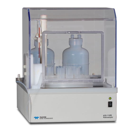
ASX-112FR Autosamplers Operator’s Manual Chapter 1: Introduction Autosampler Standard Components Figure 1-1. ASX-112FR Autosampler—Front View F Z-Drive Assembly G Y-Arm Assembly K Cover H Sample Probe E Rinse Alignment D Dual Flowing Rinse Station C Standards Vials B Sample Rack J Status LED I Power Switch A Rotary Tray... - Page 10 ASX-112FR Autosampler Operator’s Manual Chapter 1: Introduction The following components are located on the front of the autosampler and are shipped with the autosampler. Each lettered item corresponds with a callout in Figure 1-2. Rotary Tray. The rotary tray has 14 standard positions and a rectangular center cavity, which holds one sample rack in place.
- Page 11 ASX-112FR Autosamplers Operator’s Manual Chapter 1: Introduction Power/Status LED. Green light should be lit when the power is on and the autosampler is ready to operate. Cover. The cover door may be opened (using a bar latch) to add or remove sample vials or the sample rack.
-
Page 12: Additional Equipment Required
ASX-112FR Autosampler Operator’s Manual Chapter 1: Introduction On-Board Rinse Pump. The on-board rinse pump may be either a peristaltic pump or a gas displacement pump. In either configuration, the pump is located in the upper right-hand corner on the back of the autosampler. The pump moves the rinse solutions from two rinse sources through the flowing rinse station. - Page 13 0.25 mm, 0.50 mm, and 0.89 mm. NOTE: Contact Teledyne CETAC Technologies if you need additional accessories not listed, need added features to integrate the autosampler into your analytical system, or have unique requirements. Research and development of new features and accessories for the autosampler, often inspired by customer requests, is a continuing activity at Teledyne CETAC Technologies.
-
Page 14: Chemical Compatibility
CETAC’s Web site: www.cetac.com ASX-112FR Autosampler Spare Parts Catalog, available on the CD-ROM or under "Parts" on CETAC’s Web site. Teledyne CETAC Technologies Customer Service and Support: Phone: 1 (800) 369-2822 (USA only) 1 (402) 733-2829 E-mail: CETACservice@teledyne.com... -
Page 15: Choosing A Location
2 Preparing for Installation Installing the autosampler requires preparation. Before you install the autosampler, you should evaluate the physical arrangement of the laboratory to choose a suitable location. Once you choose a location, you must carefully unpack the autosampler prior to beginning the installation. This chapter discusses what requirements must be met when you choose a location. -
Page 16: Work Surface Requirements
ASX-112FR Autosampler Operator’s Manual Chapter 2: Preparing for Installation Allow at least 5 cm behind the autosampler for power cord and communication cable egress. Always position the equipment so that it is easy to disconnect the power cord. Work Surface Requirements The ASX-112FR can be conveniently placed on top of the CETAC Aridus II or Aridus3 Desolvating Nebulizer System. -
Page 17: Unpacking The Autosampler
ASX-112FR Autosamplers Operator’s Manual Chapter 2: Preparing for Installation conductors and ground. A protective ground connection by way of the grounding connector in the power cord is required for safe operation. Ensure that you position the autosampler so that the location where the power supply cord plugs into it is easily accessible (is not blocked) and it can be quickly disconnected if needed. - Page 18 ASX-112FR Autosampler Operator’s Manual Chapter 2: Preparing for Installation This page is intentionally blank.
-
Page 19: Installing The Autosampler
3 Installing the Autosampler The autosampler is designed for easy installation. Installation consists of two parts: assembling the autosampler and connecting it to the host analytical instrument. The autosampler can be installed with minimal effort; no tools are required. You can remove thumbscrews with tools if necessary, but do not tighten them with anything other than your fingers. -
Page 20: Mounting The Sample Probe Assembly
ASX-112FR Autosampler Operator’s Manual Chapter 3: Installing the Autosampler Mounting the Sample Probe Assembly Mounting the sample probe assembly on the autosampler is the first task in assembling the ASX-112FR. However, prior to mounting the probe, the installation of the Y-arm should be confirmed to be compatible with the height of the racks intended for use. - Page 21 ASX-112FR Autosamplers Operator’s Manual Chapter 3: Installing the Autosampler Figure 3-2. Sample Probe Assembly Installation. Figure 3-2 illustrates the sample probe assembly installation. The instructions below can be used for the standard probe or the uptake capillary of the C-Flow PFA nebulizer.
- Page 22 ASX-112FR Autosampler Operator’s Manual Chapter 3: Installing the Autosampler If the C-Flow PFA nebulizer is to be used, secure the uptake line of the nebulizer near the top of the built-in probe. Loosen the thumbscrew of the tubing holder block on the front left of the autosampler.
-
Page 23: Connecting The Rinse Station
ASX-112FR Autosamplers Operator’s Manual Chapter 3: Installing the Autosampler Figure 3-4. Connection of C-Flow PFA Nebulizer to Aridus3. See the CETAC Aridus II or Aridus3 Desolvating Nebulizer System Operator's Manual for more information on connecting the probe and nebulizer. Connecting the Rinse Station The cabinet-mounted rinse station is located at the left-front side of the autosampler within the cover. -
Page 24: Peristaltic Pump Configuration
ASX-112FR Autosampler Operator’s Manual Chapter 3: Installing the Autosampler Figure 3-5. Dual Flowing Rinse Station. The rinse solutions are pumped into the rinse station through two ports at the bottom of the rinse station and are drained from the top of the rinse station. This up-flow rinsing is the most effective method for decontaminating the sample probe between samples. - Page 25 ASX-112FR Autosamplers Operator’s Manual Chapter 3: Installing the Autosampler Use one length of approximately 72 inches (1.8 meters) of the 3/16 inch (5- millimeter) I.D. Tygon tubing provided for the rinse station drain. Insert one ® end into the upper drain fitting on the back of the rinse station as noted in Figure 3-6.
-
Page 26: Gas Displacement Pump Configuration
ASX-112FR Autosampler Operator’s Manual Chapter 3: Installing the Autosampler the inside channel fitting on the bottom of the peristaltic pump as shown in Figure 3-6. b) Take the free end of the Tygon tubing protruding from middle rinse ® station input and insert it onto the outside channel fitting on the bottom of the peristaltic pump as shown in Figure 3-6. -
Page 27: Argon Gas Supply For Gas Displacement Pump
ASX-112FR Autosamplers Operator’s Manual Chapter 3: Installing the Autosampler pressure to the tubing while tightening the fittings. The fittings should be as tight as you can get them using just your fingers. Use one length of approximately 72 inches (1.8 meters) of the 3/16 inch (5- millimeter) I.D. - Page 28 ASX-112FR Autosampler Operator’s Manual Chapter 3: Installing the Autosampler connected to bottle#2 with the full rinse solution. Ensure that each fitting is tight. Rinse Solution Out – Connect the gas displacement pump to the rinse station by completing the following steps: a) Take the free end of the PFA tubing (0.5 mm I.D.) protruding through the alignment block from the lower rinse station and connect it to the “RINSE 1 OUT”...
- Page 29 ASX-112FR Autosamplers Operator’s Manual Chapter 3: Installing the Autosampler Figure 3-7. Gas Displacement Pump Tubing Connections.
- Page 30 ASX-112FR Autosampler Operator’s Manual Chapter 3: Installing the Autosampler Figure 3-8. Gas Displacement Pump Fitting Connections.
- Page 31 ASX-112FR Autosamplers Operator’s Manual Chapter 3: Installing the Autosampler Figure 3-9. Gas Displacement Pump Argon Gas Connection with Aridus II. Figure 3-10. Gas Displacement Pump Argon Gas Connection with Aridus3.
-
Page 32: Assemble And Place The Sample Rack And Vials
ASX-112FR Autosampler Operator’s Manual Chapter 3: Installing the Autosampler Assemble and Place the Sample Rack and Vials Never attempt to load, unload or reposition the sample vial rack or sample WARNING vials while the autosampler is operating. The sample probe may move unexpectedly and cause an injury. -
Page 33: Tall Rack Configuration
ASX-112FR Autosamplers Operator’s Manual Chapter 3: Installing the Autosampler Three CETAC sample racks are available for the short configuration. These are shown in Figure 3-12. To assemble and place the samples and standards for a short configuration, complete the following steps: Ensure the short sample tray adapter plate is screwed into place in the center of the rotary tray. - Page 34 ASX-112FR Autosampler Operator’s Manual Chapter 3: Installing the Autosampler Two Bel-Art half racks are provided for the tall configuration. The tray layouts are shown in Figure 3-13. To assemble and place the samples and standards for a tall configuration, complete the following steps: Assemble the Bel-Art rack by snapping the middle and top sections to the bottom according to the instructions included with the rack.
-
Page 35: Connecting The Autosampler To The Power Supply
ASX-112FR Autosamplers Operator’s Manual Chapter 3: Installing the Autosampler Connecting the Autosampler to the Power Supply The autosampler is powered by the supplied external desktop "brick" power supply. Ensure that you position the autosampler so that the location where the power supply cord plugs into it is easily accessible (is not blocked) and it can be quickly disconnected if needed. -
Page 36: Connecting The Autosampler To An Analytical Instrument
ASX-112FR Autosampler Operator’s Manual Chapter 3: Installing the Autosampler Connecting the Autosampler to an Analytical Instrument You can connect the autosampler directly to a sample introduction peristaltic pump and then to the ICP-MS or to a sample introduction device, such as the CETAC Aridus II or Aridus3 Desolvating Nebulizer System. -
Page 37: Establishing An Rs-232 Serial Communications Interface
Teledyne CETAC Technologies universal port adapter kit. You can order the adapter kit from Teledyne CETAC Technologies or purchase an adapter locally to convert the serial port to a DB9M. Do not use a “null modem”... -
Page 38: Establishing A Usb Communications Interface
ASX-112FR Autosampler Operator’s Manual Chapter 3: Installing the Autosampler Establishing a USB Communications Interface If the host computer does not have an available RS-232 port, you can use a USB port instead. An “A-B” USB cable may be obtained from any computer store. The procedure for finding and installing the USB driver may be different, depending on your computer's operating system. - Page 39 ASX-112FR Autosamplers Operator’s Manual Chapter 3: Installing the Autosampler Figure 3-16 Choosing to install USB driver from a CD Select Search removable media. Figure 3-17 Choosing to install USB driver from a CD d. Wait while the computer searches the CD.
- Page 40 ASX-112FR Autosampler Operator’s Manual Chapter 3: Installing the Autosampler Figure 3-18 Searching the CD When the driver is found, select it and click Next. Figure 3-19 Selecting the driver The driver installation is complete.
- Page 41 ASX-112FR Autosamplers Operator’s Manual Chapter 3: Installing the Autosampler Figure 3-20 Driver installation is complete If a message is displayed showing which COM port number was chosen (look for a “bubble” in the lower-right corner of the screen), make a note of Confirm that the COM port selected for the USB matches the port selected in the host computer's ICP-MS software.
-
Page 42: Establishing An Ieee Communications Interface
ASX-112FR Autosampler Operator’s Manual Chapter 3: Installing the Autosampler Establishing an IEEE Communications Interface Before you can establish an IEEE communications interface with the host computer, you must have the IEEE-488 interface kit, which includes a converter box and an IEEE-488 cable. Use the IEEE-488 kit to establish a parallel interface with the host computer. -
Page 43: Testing The Communications Interface
4 Verifying Installation Once installation of the autosampler is complete, it is important to verify that you have installed it correctly. Attempting to use it before ensuring that it is installed correctly may result in damage to the autosampler. Verifying installation of the autosampler consists of two parts: ... -
Page 44: Checking The Autosampler Components
ASX-112FR Autosampler Operator’s Manual Chapter 4: Verifying Installation Enter the RINSE command. The Y-arm should dip first into the center of the pre-rinse location and then into the center of the full rinse location. NOTE: The autosampler Y-arm and probe can usually be sent to the HOME and RINSE positions by clicking a button in the host ICP-MS software. - Page 45 Check that the sample probe correctly accesses each position and that the probe descends into the center of each sample vial. NOTE: If the autosampler alignment is not correct, contact Teledyne CETAC Technologies Customer Service and Support or an authorized representative.
- Page 46 ASX-112FR Autosampler Operator’s Manual Chapter 4: Verifying Installation This page is intentionally blank.
-
Page 47: Establishing Optimal Operating Conditions
5 Using the Autosampler Before using the autosampler, ensure that your lab environment provides operating conditions that will prolong the life of the autosampler. Once the proper operating conditions are met, you can arrange the sample vial racks and start the autosampler sequence run. When you finish using the autosampler, you may need to flush the rinse station and flow path before shutting the autosampler down. -
Page 48: Replacing Auto Sampler Components
ASX-112FR Autosampler Operator’s Manual Chapter 5: Using the Autosampler Observe the same general electrostatic discharge precautions as with any other integrated circuit electronic devices. Low humidity environments, especially when combined with static-generating materials, require maximum care. Discharge static buildup and ground to the autosampler base or cabinet before CAUTION performing any maintenance. -
Page 49: Arranging The Sample Vial Racks
ASX-112FR Autosamplers Operator’s Manual Chapter 5: Using the Autosampler Use of mismatched sample vials and sample vial racks may result in malfunctions CAUTION To order additional supplies, refer to the CETAC Accessories and Supplies or sample spills. Be sure your vials meet the given requirements. Catalog for the autosampler, available on the CD or on the CETAC Web site, www.cetac.com. -
Page 50: Shutting Down The Autosampler
ASX-112FR Autosampler Operator’s Manual Chapter 5: Using the Autosampler Ensure there are no air bubbles visible in the rinse uptake tubing before you run samples with the autosampler. Access the host computer’s ICP-MS software and activate the autosampler program. Define and start the sampling sequence. The autosampler runs until it reaches the end of the sampling sequence. -
Page 51: Reconfiguring The Autosampler Sample Height
ASX-112FR Autosamplers Operator’s Manual Chapter 5: Using the Autosampler To flush the rinse station and flow path, complete the following steps: Insert the rinse uptake tubing into a deionized water source. NOTE If you are flushing the rinse system during initial startup, first use a 2% nitric acid solution as the rinse agent, followed by deionized water. -
Page 52: Reconfiguring The Autosampler Icp-Ms Personality
"personality" which enables it to follow the commands issued by the customer's particular model of ICP-MS instrument. If the autosampler is to be used with a different model ICP-MS, the autosampler personality must be changed. Please contact CETAC at CETACservice@teledyne.com for instructions. Changing the Peristaltic Pump Speed A software control tool is available to control the speed of the back-panel mounted peristaltic pump (if the ASX-112FR is so equipped). -
Page 53: Changing The Pump Speed
ASX-112FR Autosamplers Operator’s Manual Chapter 5: Using the Autosampler Double-click “ASX-11x Pump Speed – 1.0.0. Figure 5-2. Running the Pump Speed Application (CD Contents May Vary). A shortcut icon will appear that can be used to easily access the pump speed control Figure 5-3. - Page 54 ASX-112FR Autosampler Operator’s Manual Chapter 5: Using the Autosampler This page is intentionally blank...
-
Page 55: Cleaning The Autosampler
6 Maintaining the Autosampler Routine maintenance of the autosampler includes cleaning of specific autosampler components. Routine maintenance also includes checking for leaks or other damage. Additional periodic maintenance tasks may be required, including replacement of the following autosampler components: peristaltic pump tubing, rinse tubing, and sample probe. Discharge static buildup and ground to the autosampler base or cabinet before CAUTION performing any maintenance. -
Page 56: Thorough Cleaning
ASX-112FR Autosampler Operator’s Manual Chapter 6: Maintaining the Autosampler Shut down and unplug the autosampler power cord. For information about shutting down the autosampler, see page 50. Remove the cover. Remove the sample and standards vials and the sample rack. Wipe the rotary tray, spill tray, autosampler cabinet, autosampler arm, and cover using a damp clean-room wiper. -
Page 57: Checking For Leaks
ASX-112FR Autosamplers Operator’s Manual Chapter 6: Maintaining the Autosampler Dampen the clean-room wiper with deionized water or a 70% isopropyl alcohol/30% deionized water solution. Pay special attention to the inside of the cover, spill tray, Z-drive assembly, rinse station, and the rinse alignment block. -
Page 58: Replacing The Rinse Station
ASX-112FR Autosampler Operator’s Manual Chapter 6: Maintaining the Autosampler Remove the short rack adapter plate (if using) by removing the four corner screws. Be sure to keep the screws with the adapter plate for reinstallation. Remove the three screws holding the rotary tray in place and gently lift the rotary tray up and off the two placement pegs. - Page 59 ASX-112FR Autosamplers Operator’s Manual Chapter 6: Maintaining the Autosampler the proper vessel(s) before restarting and operating the autosampler.) b. (Gas displacement pump-equipped models) i. Drain the rinse system by raising the rinse solution uptake tubing to a position that is above the liquid level in each rinse vessel (Use caution to ensure that each rinse solution vessel is not pressurized while performing this operation).
-
Page 60: Replacing Peristaltic Pump Tubing
ASX-112FR Autosampler Operator’s Manual Chapter 6: Maintaining the Autosampler Check all rinse tubing to ensure it is properly attached. Restore power to the autosampler. For more information on proper tubing installation, see Chapter 3, “Installing the Autosampler.” NOTE: Prior to removing the rinse station, it is important to safely and fully drain/evacuate the entire rinse system. -
Page 61: Replacing The Sample Probe
ASX-112FR Autosamplers Operator’s Manual Chapter 6: Maintaining the Autosampler Replacing the Sample Probe You must replace the sample probe if it is leaking or shows other signs of deterioration. To do this, complete the following steps: Shut down and unplug the autosampler power cord. Remove the old sample probe and tubing. -
Page 62: Spare Parts
ASX-112FR Autosampler Operator’s Manual Chapter 6: Maintaining the Autosampler Spare Parts Spare parts may be obtained by contacting CETAC or your authorized CETAC distributor. Part numbers are subject to change; visit www.cetac.com for a complete list of currently available spare parts. Peristaltic Pump Tubing Part Number Description... -
Page 63: Power System Problems
This chapter explains how to troubleshoot autosampler problems. If you cannot solve a problem using the steps given in this chapter, you should contact Teledyne CETAC Technologies Customer Service and Support. Power System Problems A possible cause of system malfunction is a problem in the power system. If the system is not functional, it is possible that it is not receiving power. -
Page 64: Communications Interface Problems
If the cords are properly connected, power is available, the external power supply is good, and the unit still does not initiate, continue troubleshooting or contact CETAC at CETACservice@teledyne.com. Communications Interface Problems Operation of the autosampler is directed by the host computer. A malfunction... -
Page 65: Alignment Problems
ASX-112FR Autosamplers Operator’s Manual Chapter 7: Troubleshooting the Autosampler USB Cable Problems Either RS-232 or USB may be used, but not both at once. Check the USB cable to ensure it is plugged into the port on the autosampler. Check the host computer to ensure that the USB cable is connected to the appropriate USB port. -
Page 66: Returning The Product To Cetac For Service
Product Warranty Statement NOTE Contact Teledyne CETAC Technologies or refer to the warranty card which came with your product for the exact terms of your warranty. The following copy is provided for your convenience, but warranty terms may be different for your purchase or may have changed after this manual was published. -
Page 67: Returned Product Procedures
ASX-112FR Autosamplers Operator’s Manual Chapter 7: Troubleshooting the Autosampler products please visit our web site at www.cetac.com and follow the Automation link. The unit, including any defective part, must be returned to CETAC within the warranty period. The expense of returning the unit to CETAC for warranty service will be paid for by the buyer. -
Page 68: Returned Product Warranty Determination
ASX-112FR Autosampler Operator’s Manual Chapter 7: Troubleshooting the Autosampler thirty (30) days after issuance of a return authorization number will be subject to review. Shipment of repaired products will generally be made forty-eight (48) hours after the receipt. Do not return products which are contaminated by radioactive materials, infectious agents, or other materials constituting health hazards to CETAC employees. -
Page 69: Using C-Term
8 Operating a CETAC Autosampler Using a Terminal Program The autosampler can be controlled using a serial communications protocol. You can use any terminal emulation program, including: C-Term. This program is installed with the Xpress Configuration Tool software, and runs on Windows 2000 and later. (recommended) ... -
Page 70: Overview Of The C-Term Window
ASX-112FR Autosampler Operator’s Manual Chapter 8: Operating a CETAC Autosampler Using a Terminal Program Figure 8-1 Starting C-Term Once C-Term is loaded, the window shown in Figure 8-2 will open. The Overview of the C-Term Window majority of C-Term’s functions are available from this window. Figure 8-2 C-Term Window By default, typed commands are sent to the CETAC device connected to the opened port. -
Page 71: Configuring C-Term
ASX-112FR Autosamplers Operator’s Manual Chapter 8: Operating a CETAC Autosampler Using a Terminal Program Figure 8-3 Outgoing commands shown in green and incoming responses shown in red By default, C-Term attempts to open COM1 the first time it is executed. If the Configuring C-Term COM port that the CETAC device is connected to is not the default (COM1), then it will be necessary to configure C-Term to use the desired port. -
Page 72: Using Hyperterminal
ASX-112FR Autosampler Operator’s Manual Chapter 8: Operating a CETAC Autosampler Using a Terminal Program The window will close and the settings will be saved. These new settings will be applied immediately and used thereafter unless changed again. NOTE Except for the ASX-8000, all CETAC devices communicate at 9600 baud (which is the default.) NOTE Only installed COM ports, including USB virtual COM ports, will appear in the... - Page 73 ASX-112FR Autosamplers Operator’s Manual Chapter 8: Operating a CETAC Autosampler Using a Terminal Program A window will appear as in Figure 8-6. Enter COM 1 in the name box. Press the OK button. Figure 8-6 “Connection Description” Window In the Connect To window, set Connect Using to COM 1, then click OK. Figure 8-7 “Connect To”...
- Page 74 ASX-112FR Autosampler Operator’s Manual Chapter 8: Operating a CETAC Autosampler Using a Terminal Program “COM1 Properties” Window Figure 8-8 Click OK. The HyperTerminal window will open. Figure 8-9 “Com 1 Hyperterminal” Window On the File menu, click Properties.
- Page 75 ASX-112FR Autosamplers Operator’s Manual Chapter 8: Operating a CETAC Autosampler Using a Terminal Program On the Settings tab, click ASCII Setup “Com 1 Properties” Window Figure 8-10 Click ASCII Setup. Enable “Echo typed characters locally” and “Append line feeds to incoming line ends,”...
-
Page 76: Autosampler Commands
ASX-112FR Autosampler Operator’s Manual Chapter 8: Operating a CETAC Autosampler Using a Terminal Program “ASCII Setup” Window Figure 8-11 Turn on the autosampler. The HyperTerminal window should display an OK. Autosampler Commands The following commands will produce various responses from the autosampler. -
Page 77: Characteristics
ASX-112FR Autosamplers Operator’s Manual Chapter 9: Safety and Regulatory Information 9 Safety and Regulatory Information Review this product and related documentation to familiarize with safety markings and instructions before you operate the instrument. Characteristics Environmental Characteristics These environmental characteristics indicate the conditions for safe operation. -
Page 78: Electrical Characteristics
ASX-112FR Autosampler Operator’s Manual Chapter 9: Safety and Regulatory Information Electrical Characteristics Power requirements Power Supply Input: AC Voltage, Frequency, and Current 100-240 V ~ 47-63 Hz 1.07 A Installation Category: CAT II (Line voltage in appliance and to wall outlet) Output: 24 V DC, 3.33 A Autosampler... -
Page 79: Safety Notices
Safety Notices INJURY HAZARD WARNING If the equipment is used in a manner not specified by Teledyne CETAC Technologies, the protection provided the equipment may be impaired. Repair or service that this not covered in this manual should only be performed by qualified personnel. -
Page 80: Cleaning Instructions
ASX-112FR Autosampler Operator’s Manual Chapter 9: Safety and Regulatory Information Cleaning Instructions For additional cleaning information, see “cleaning” in the index. To clean the exterior surfaces of the instrument, complete the following steps: Shut down and unplug the instrument. Wipe the instrument exterior surfaces only using a towel dampened with a lab-grade cleaning agent. -
Page 81: Operating Environment
ASX-112FR Autosamplers Operator’s Manual Chapter 9: Safety and Regulatory Information Operating Environment SHOCK HAZARD WARNING To reduce the risk of fire hazard and electrical shock, do not expose the unit to rain or humidity. To reduce the risk of electrical shock, do not open the cabinet. -
Page 82: Explanation Of Caution And Warning Notices
ASX-112FR Autosampler Operator’s Manual Chapter 9: Safety and Regulatory Information Explanation of Caution and Warning Notices Warning symbol marked on equipment. This symbol means “Attention! Refer to the manual.” Crush Hazard / Pinch Point – Keep hands clear of moving parts. X, Y, Z axis movement may crush hand. -
Page 83: Avertissements En Français
ASX-112FR Autosamplers Operator’s Manual Chapter 9: Safety and Regulatory Information Avertissements en Français This section provides French translations of notices which may appear on the instrument or on other instruments used as part of the measurement system. AVERTISSEMENT POUR UNE PROTECTION CONTINUÉ CONTRE LES RISQUES D’INCENDIE, REMPLACER UNIQUEMENT PAR DES FUSIBLES DE MÊME TYPE ET AMPÈRAGE. -
Page 84: Electromagnetic Interference
The FCC requires the user to be notified that any changes or modifications made to this device that MODIFICATIONS are not expressly approved by Teledyne CETAC Technologies may void the user's authority to operate the equipment. Connections to this device must be made with shielded cables with metallic RFI/EMI connector CABLES hoods to maintain compliance with FCC Rules and Regulations. -
Page 85: 10 Glossary
10 Glossary Analytical Instrument: The instrument, typically an ICP-AES or ICP-MS, to which the autosampler is connected. Arm: The autosampler arm that extends from the ASX-112FR Z-drive assembly. The arm moves left/right and the Z-drive assembly moves up and down. The sample probe is attached to the arm. COM Port: A serial communications connection between the autosampler and the host computer. - Page 86 ASX-112FR Autosampler Operator’s Manual Chapter 10: Glossary PEEK: Polyetheretherketone. Peristaltic Pump: In the context of this manual, usually refers to the on-board peristaltic pump controlling the movement of the rinse solutions to the autosampler rinse station. PET: Polyethylene terephthalate. PFA: Perfluoroalkyoxy. PPS: Polyphenylene sulphide.
- Page 87 Index avertissements, 83 operator qualifications, 8 avis Canadien, 84 personality, 52 chemical compatibility, 14 physical characteristics, 15 chemical hazards, 16 pollution degree, 77 cleaning, 55, 80 power commands connections, 35 autosampler, 76 power-on procedure, 49 compatibility, 52 requirements, 16, 78 condensation.
- Page 88 480159 Manual Part Number Rev 6 Printed in USA...