Table of Contents
Advertisement
Quick Links
Advertisement
Table of Contents

Related Manuals for JRC JR-8600


Summary of Contents for JRC JR-8600
- Page 1 JLR-8600 NWZ-1650 GPS NAVIGATOR INSTRUCTION MANUAL...
- Page 2 Foreword Thank you for purchasing the JRC GPS Navigator JLR-8600. This equipment is a high-performance navigation equipment consisting of a GPS sensor and navigator, can retrieve the position data using the GPS sensor to display various navigation information on the display.
-
Page 3: Before Commencing The Operation
Before Commencing the Operation Symbols Several symbols are used in this manual to ensure safety and proper operation of the equipment and to avoid possible human injury or property damage. These symbols and their meanings are shown below. Please read and understand these symbols before proceeding to read this manual. -
Page 4: Precautions Upon The Operation
Do not perform internal inspections or modifications of the equipment. Inspection or modification by unauthorized personnel may result in fire, electric shock, or equipment failure. Please consult with JRC or an affiliate to perform internal inspections or repair. When disposing of the used lithium battery, place insulating tape over the battery terminals, or otherwise insulate the battery. - Page 5 Do not place any item on the top of the equipment. Doing so may result in equipment failure, malfunction, or injury. Please consult with JRC or an affiliate to perform installation. Installation by unauthorized personnel may result in malfunction.
- Page 6 CAUTION When connecting the cable attached to the equipment, do not bend it acutely, twist it, or impart excessive force. Doing so sometimes causes cracks or damage to the coating, resulting in fire or electrocution. Do not install the sensor where there is excessive vibration. Vibration may cause sensor failure.
-
Page 7: Appearance Of The Equipment
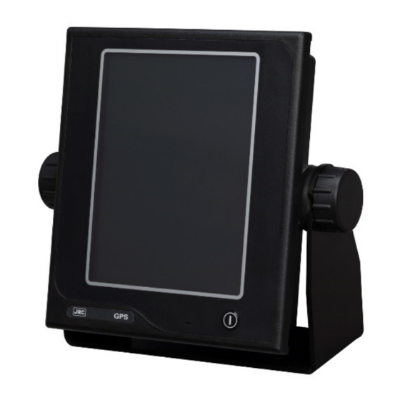
Appearance of the Equipment ●NWZ-1650 Display Unit ●NDC-4100 Processor Unit ●JLR-4350 GPS Sensor Unit... -
Page 8: Terminology
Terminology Term Meaning (Descriptions) 2D (2 dimension) Positioning with antenna elevation height in addition to satellite data. 3D (3 dimension) The three dimensional position fix, 4 or more satellites required. Active route Route that is currently used by a ship Anchor alert This alert monitors that the own ship is the preset distance or more away from the waypoint. - Page 9 1st numeral: Against ingress of solid foreign objects (0 – 6) 2nd numeral: Against ingress of water with harmful effects (0 - 8). (IPX4: splash-proof, IPX6: waterproof) IP address ID number assigned to equipment on a constructed network. Abbreviation of Local Area Network. A network is constructed for transmitting and receiving data.
- Page 10 Shared route Function that uses the same route as other functions such as ECDIS do. The route can be updated automatically by sharing the active route. Smoothing Function for averaging over a specified number of seconds. Speed Over Ground, This is the ship’s relative speed to the ground. SPEED The speed mainly measured by the GPS.
-
Page 11: Table Of Contents
Index Foreword ............................... ii Before Commencing the Operation ..................... iii Precautions Upon the Operation ......................iv Appearance of the Equipment ......................vii Terminology ............................viii Functions ..........................1-1 Features ..........................1-1 Configuration ......................... 1-2 1.3.1 Standard Configuration ....................1-2 1.3.2 Option .......................... - Page 12 4.5.4 Copying routes ......................4-28 4.5.5 Deleting routes ......................4-29 4.5.6 Sharing a route with another piece of equipment ............4-31 4.5.7 Setting route initial values .................... 4-32 Executing a Route ....................... 4-33 4.6.1 Executing a route by selecting from a route list ............4-33 4.6.2 Selecting a waypoint/route by using the GOTO key ............
- Page 13 4.20 Measuring a distance and an azimuth between two points ..........4-73 Chapter 5 Maintenance and Inspection ..................5-1 General Maintenance and Inspection ................... 5-1 Alerts ............................. 5-2 Troubleshooting ........................5-5 Replacement Parts ........................ 5-7 5.4.1 Repair units ........................5-7 5.4.2 Regular replacement parts ....................
-
Page 15: Functions
Chapter 1 Equipment Overview Functions This equipment (JLR-8600) is a GPS navigator with a JLR-4350GPS sensor that is connected to the NWZ-1650 display unit and the NDC-4100 processing unit. JLR-4350, which is a multi-GNSS receiver that is capable of receiving data from GPS as well as GLONASS or BeiDou, operates around-the-clock to measure positions with high accuracy anywhere in the world and in all weather conditions by using the GPS satellite and the GLONASS satellite, or the BeiDou satellite, and produces highly reliable positioning results. -
Page 16: Configuration
Configuration 1.3.1 Standard Configuration JLR-8600 Name Model Q'ty Note GPS Sensor Unit JLR-4350 Screw Adapter MTV302007A Mounting Band MPBP02520 Include 2 bands Instruction manual 7ZPNA4695 English Cable guard rubber MPPK31462 Processor Unit NDC-4100 MF51NR 250V 5 :4 Fuses MF51NR 250V 5 Fuse MF51NR 250V 2 MF51NR 250V 2 :1 Fuses... -
Page 17: Option
1.3.2 Option Name Model Q'ty Note AC/DC Power supply 100/220VAC,24VDC Input NBG-320 unit 12VDC Output AC/DC Power supply 100/220VAC,24VDC Input NBD-577C unit 24VDC Output AC/DC Power supply 100/220VAC,24VDC Input NBD-904 unit 24VDC Output Data Power Cable CFQ-7539 For Remote Display/ 8 cores 15m Data power Cable CFQ-7539-5 For Remote Display/ 8 cores 5m... -
Page 18: Construction
Construction NWZ-1650 Display Unit Unit: mm Mass: Approximately 2kg Color: Munsell N2.5 IP Grade: IP56 NDC-4100 Processor Unit Unit: mm Mass: Approximately 2.2kg Color: Munsell N2.5 IP Grade: IP22... - Page 19 JLR-4350 GPS Sensor Unit Unit: mm Mass: Approximately 1.5kg (include 15m cable) Color: Munsell N9 IP Grade: IP56 (IEC60945)
- Page 20 NBD-904 Power Supply Unit: mm Mass:Approximately 2.6 kg NBD-577C Power Supply Unit: mm Mass: Approximately 5.4 kg...
- Page 21 NBG-320 Power Supply Unit: mm Mass: Approximately 3.5 kg NQE-7700A Junction Box GPS cable Glandφ15 Glandφ25 Unit: mm Mass: Approximately 0.6 kg...
- Page 22 NQD-4414 Coaxial Cable Kit (NQD-4410) Screw M8 Unit: mm Mass: Approximately 1.5 kg NQD-4414 Coaxial Cable Kit (NQD-4411) (Screw M3) Unit: mm Mass: Approximately 0.7 kg...
- Page 23 NQA-4351A Output Buffer DC Input Data Output (IEC61162-1 or NMEA) (IEC61162-1 or NMEA) Select signal JUMPER SETTING for DC Input DC Input JUMPER Terminal DC 12V TB1-IN JUMPER ON 9-16V JUMPER Cable 0.25~2.5mm DC 24V TB1-IN JUMPER ON 9-16V Not connect Data Output Data Output (IEC61162-1 or NMEA) (IEC61162-1 or NMEA)
- Page 24 NCZ-777 Select Switch Unit: mm Mass: Approximately 0.5 kg NCZ-777 Select Switch (Flush Mounting) Unit: mm Mass: Approximately 0.7 kg 1-10...
- Page 25 NCZ-1663 Select Switch Unit: mm Mass: 0.2 kg NCZ-1663 Select Switch (Flush Mounting) 1-11...
- Page 26 Unit: mm Mass: 0.2 kg NCZ-1537A/B Select Switch (Flush Mounting) Unit: mm Mass: 0.55 kg 1-12...
- Page 27 CQD-10 Junction Box Unit: mm Mass: Approximately 1.1 kg NKG-104 Printer Unit: mm Mass: Approximately 2.1 kg 1-13...
-
Page 28: System Diagram
System Diagram JLR-4350 GPS Sensor NWZ-1650 Display Unit NQE-7700A Junction Box 250V-MPYCYS-7 CFQ-7540 Sensor Display Unit ECDIS Ethernet×2 Remote Maintenance 250V-TTYCS-1 External equipment RS-422 IN×2 OUT×5 NDC-4100 Processor Unit 250V-TTYCS-1 Alarm System IN×1 OUT×4 Contact Radar 250V-TTYCS-1 RS-422 ECDIS/Plotter (Internal Buffer) OUT×8 Tide Current Calculator Printer NKG-104... -
Page 29: Chapter 2 Name And Function Of Each Unit
Chapter 2 Name and Function of Each Unit NWZ-1650 DISPLAY UNIT Status area Displays the status of the equipment or system with the icon. DISPLAY Displays the information of own ship and equipment setting screen. Operated by the touch panel. Power supply key Buzzer Touch panel... - Page 30 How to read the information on the display Date and time display (note1 U: UTC L: Local Geodetic In the 12-hour display, AM/PM positioning system is displayed. RAIM Status Displays the currently set See the status list accuracy level. for the contents of ...
-
Page 31: Jlr-4350 Gps Sensor
JLR-4350 GPS Sensor Radome 6 pins Connector Approx. φ19mm Base Mounting Screw Data Cable 15m 1 inch 14 UNS-2B Approx. φ6mm NDC-4100 Processor Mounting Screw hole Cover Cable Inlet Earth terminal... -
Page 33: Chapter 3 Display Screens
Chapter 3 Display Screens Display Screens 3.1.1 Switching display When the screen key is tapped, a display screen list is displayed. Select a screen to be displayed from the list. The screen name is displayed on the screen key. On the navigation information screen, the analogue screen, and the navigation support screen, a sub screen can be displayed by using Display screen list 3.1.2... - Page 34 Sub screen a) If there are no waypoints Sub Screen 1 (4 digit position screen) Own ship's position (latitude and longitude) Speed Course Sub Screen 2 (SOG and COG screen) Own ship's position (latitude and longitude) Speed Course...
- Page 35 b) If there are waypoints Sub Screen 1 (4 digit position screen) Number of the waypoint Route number for which the ship is heading Own ship's position (latitude and longitude) Speed Course Distance from the own Bearing from the own ship's ship's position to the position to the waypoint waypoint...
- Page 36 Memo VTD (Speed of the destination component) VTD (An acronym of "Velocity Toward Destination) This in an index that shows how fast the boat is approaching toward the destination in the unit of knot when it is navigation at a given bearing angle and speed. VEAR(Speed of the COG component) VEAR(An acronym of "Velocity Along Route") This in an index that shows how fast the vessel is approaching along the planned route in...
-
Page 37: Plotting Screen 1
3.1.3 Plotting screen 1 Plotting screen 1 displays the course, speed, bearing, and distance at the bottom of the screen. The screen can be enhanced and reduced by using Date and Time Event symbol Own ship's position (latitude and longitude) Northerly directions Waypoint symbol... -
Page 38: Analogue Screen
3.1.5 Analogue screen The analogue screen displays the course, waypoint bearing, and CDI in graphic format. During route execution, the screen displays the off-course and distance to the waypoint. The ship speed meter can be displayed by using Main screen ▼Bearing from the own ship's position Course indicator bar... -
Page 39: Highway Screen
3.1.6 Highway screen The highway screen displays the CDI, course, speed, bearing, and distance. The screen can be enhanced or reduced by using respectively. Deviation from the route and the steering direction Waypoint direction Waypoint Next waypoint Route Scale bar Speed Own ship Course... -
Page 40: Waypoint Information Screen
3.1.8 Waypoint information screen The waypoint information screen displays waypoint information on the route. The information can be switched to the next waypoint information by using Waypoint number n-th waypoint Total number of waypoints Comment on Bearing from the own the waypoint ship's position to the displayed waypoint... -
Page 41: Navigation Aid Screen
3.1.10 Navigation aid screen The navigation aid screen calculates and displays navigation information including a 4-split screen, navigation measurement, trip distance, external equipment information, and distance between two points. The screen can be switched by using Navigation assistance screen 1 Speed Course Distance from the own... - Page 42 Navigation assistance screen 3 (measurement for navigation) RUNNING: Measurement in progress END: Measurement complete measurement start time measurement end time Total time trip Average speed RUNNING: Measurement in progress measurement start time END: Measurement complete measurement end time Total time Average speed trip Navigation assistance screen 4 (External equipment screen)
-
Page 43: Chapter 4 Operation
Chapter 4 Operation Menu List 4.1.1 Main Menu MENU Sub Menu Sub Menu Sub Menu Range Reference THEME DAY/DUSK/NIGHT BEEP OFF / ON DAY SCREEN OFF / ON OFF / ON PLOT OFF / ON DISPLAY ANALOG OFF / ON HIGHWAY OFF / ON SAT INFO... - Page 44 MENU Sub Menu Sub Menu Sub Menu Range Reference ACTUAL OFF / ON COURSE SOUND OFF / ON CHANGE TEMP SOUND OFF / ON DPTH SOUND OFF / ON ALERT GPS→DGPS DGPS→GPS DGPS GPS⇔DGPS SOUND OFF / ON OFF / ON BUFFER SOUND OFF / ON...
- Page 45 MENU Sub Menu Sub Menu Sub Menu Range Reference GNSS GPS MODE FIX MODE 2D / 3D / AUTO ELV MASK 5~89 deg HDOP 4/10/20 POSN 0~99 SMOOTHING(s) SPEED SMOOTH 0~99 SMOOTHING(s) COURSE 0~99 SMOOTHING(s) RAIM RAIM ACCURACY OFF/10/30/50/100 LEVEL(m) DATUM QUADRANT GNSS...
- Page 46 MENU Sub Menu Sub Menu Sub Menu Sub Menu Range Reference MAIN DISPLAY REMOTE(LAN) TYPE1 / 2 TYPE REMOTE DISPLAY (SERIAL) GP0000 DEVICE No. No1.~No3. GP0000 TYPE SENSOR1 TYPE2/2 COMPASS PROCESSOR OTHER EQUIP SENSOR2 COMPASS OTHER EQUIP IN/OUT1 IN/OUT2 IN/OUT3 OUT4 OUT5 OUT6...
- Page 47 MENU Sub Menu Sub Menu Sub Menu Sub Menu Range Reference DIMMER 1~10 GROUP DISPLAY OFF/ON NCM-227 OFF/ON SETTINGS DIMMER OFF/ON OFF/ON GP DDC OFF/ON DIMMER CAL MIN/MAX IP ADDRESS ADDRESS SUBNET DISPLAY MASK DEFAULT GATEWAY IP ADDRESS ADDRESS PROCESSOR SUBNET LAN 0 MASK...
- Page 48 MENU Sub Menu Sub Menu Sub Menu Sub Menu Range Reference MAINTENA DISPLAY PROCESSOR DIAGNOSIS SENSOR1 SENSOR2 DATA IN1 DATA IN2 DATA IN3 RS-232C MONITOR SWITCH LAN1 LAN2 SENSOR1 SENSOR2 OPERATING OPERATING TIME(hr) TIME LCD TIME(hr) RESET DEMO TYPE START/ STOP YEAR EQUIP MONTH...
-
Page 49: Function Menu
4.1.2 Function menu DISPLAY FUNC Outputs data to a printer. PRINT GOTO Sets a waypoint. COMMON EVENT Registers the own ship’s position in the event mark list. Resets the dimmer setting to the default value. DIMMER DEFAULT Displays a mark at the cursor position. MARK Displays a cursor. -
Page 50: Basic Operation
Basic Operation 4.2.1 Turning on the power of the unit When the power of the equipment is turned on by pressing the Power key, the startup screen appears. When installation is completed, self-diagnosis starts and the setting value confirmation screen is changed to the normal screen. -
Page 51: Turning Off The Power Of The Unit
2) Error startup 1 The message that is shown below may be displayed in the receiver diagnosis. This message is displayed when the setting values do not match between the processor and the receiver due to the equipment replacement or other reason. In this case, select one of the following items. -
Page 52: Adjusting The Backlight
4.2.4 Adjusting the backlight The brightness can be adjusted to 17 levels/OFF by using the DIM key. Even if the brightness is set to OFF, the DIM key alone remains lit. To reset the brightness to the default value, tap from 1. -
Page 53: Alert And Acknowledgment (Ack)
4.2.6 Alert and acknowledgment (ACK) Notifying the occurrence of an alert When an alert occurs, an alert icon is displayed at the top left corner of the screen and the occurrence of an alert is notified by a buzzer sound. The alert target value is displayed with blinking. - Page 54 Screen transition at the occurrence of an alert An alert occurrence icon is displayed. Alert occurred 2. Alert occurred (Non ACK) 1. Operating normally Tap the alert occurrence icon. The icon indicating an acknowledged state is displayed. Acknowledge by tapping the alert contents.
-
Page 55: Screen Operation
4.2.7 Screen operation See below for the screen operation. Menu level Page Setting item Setting value Page feed (< >) Move to the next page +/- setting Blue underline value switching Indicates that numeric key input is enabled. Return to the main screen Returns to the full Returns to the top menu... -
Page 56: Inputting Comments
4.2.9 Inputting comments Input of characters by using numeric keys is allowed for the setting items with blue underline. Tap the blue underline of the setting item to be input. Change the input mode by tapping ABC (characters), #&$ (symbols), or 123 (numeric values). Display the character or numeric value that is assigned to the key by tapping it. -
Page 57: List Operation
4.2.10 List operation This section shows the list operation method. The same operation method is applied for a waypoint list, a route list, and an event mark list. Menu level Page Page feed (< >) Move to the next page. No. -
Page 58: Setting Display
Setting Display Set a screen. Set a THEME, a beep tone, and background colour. 4.3.1 Setting a theme Screen brightness can be adjusted according to the time zone for using this equipment. Procedure THEME 1. THEME Description Specify this when using the equipment during daytime. DUSK Specify this when using the equipment at dusk. -
Page 59: Selecting A Display Screen
4.3.4 Selecting a display screen A screen to be displayed can be selected. It is not possible to set all the screens to non-display. Procedure Select a display. DISPLAY Description ON: Set to Display. PLOT1 OFF: Set to Non-display. PLOT2 ANALOG HIGH WAY... -
Page 60: Registering Waypoints
Registering Waypoints To execute a route, a waypoint must be registered in a waypoint list. This equipment allows registration of 10000 waypoints. A waypoint list is divided into three areas and it is managed by numbers from 1 to 11024. 1 to 10000: Waypoints that are registered in this equipment are registered. - Page 61 4.4.2 Registering waypoints The following five positions can be registered in a waypoint list. (1) Own ship’s position (2) Any latitude and longitude (3) Cursor position (4) Position measured by the bearing and distance from any position (5) Position that is registered in an event/mark list Up to 10000 points can be registered.
- Page 62 (1) When selecting OWN SHIP a) Tap b) Set a comment, a symbol, and a colour, and tap (2) When selecting MANUAL a) Tap Item Description QUADRANT Select North latitude/South latitude/East latitude/West latitude of the latitude/longitude. North latitude/East latitude North latitude/West latitude South latitude/East latitude South latitude/West latitude Enter a latitude.
- Page 63 (4) Selecting BRG/DIST a) Tap b) When a waypoint position screen is displayed, tap WPT POSN. Enter a starting position, a bearing, and a distance. c) Set a starting position, a bearing, and a distance. The submenu for setting a starting position is outlined below. (1) OWN SHIP: Set an own ship’s position.
-
Page 64: Editing Waypoints
4.4.3 Editing waypoints Registered waypoint information (symbol shape, comment, and waypoint position) can be edited. The waypoint on the route that is currently being executed cannot be edited. Procedure A waypoint list is displayed. 2. Tap the number you want to edit. 3. -
Page 65: Deleting Waypoints
4. Confirm the operation by tapping Memo When selecting copy sources with consecutive numbers, numbers that cross over a boundary such as 10000 or 10512 cannot be selected. Example) Numbers from 9999 to 10001 or numbers from 10511 to 10513 cannot be selected. -
Page 66: Route Plan
Route Plan A route can be created by using registered waypoints. Up to 100 routes can be created in this equipment and up to 512 waypoints can be specified per route. Waypoint information can be set for each LEG such as a route width, an arrival radius, and GC/RL. -
Page 67: Creating Routes
4.5.2 Creating routes To create a route, determine a route number and sequentially select the waypoints, which are turn points. The same waypoint cannot be selected continuously. Up to 100 routes can be created. Up to 512 waypoints can be set per route. ... - Page 68 Item Description POSN When "POSN" is tapped, a waypoint list is displayed. Select a waypoint position from the waypoint list. COMMENT A comment cannot be set for a waypoint. It can be edited from the waypoint list. SYMBOL A waypoint symbol cannot be set. It can be edited from the waypoint list.
-
Page 69: Editing Routes
4.5.3 Editing routes Waypoint addition, change, and deletion are allowed for routes. Procedure A route list is displayed. 2. Tap a route you want to edit. 3. Tap 4. Tap a waypoint you want to edit. Tap a route you want to edit Tap a waypoint you want to edit Route list Display of waypoints on the... -
Page 70: Copying Routes
4.5.4 Copying routes The route that was created can be copied on to a different route number. The waypoint that is used by the shared active route and is sent from ECDIS and is saved in number 101 is overwritten automatically when the next route is sent. Routes that are to be saved must be copied on to numbers between 1 and 100. -
Page 71: Deleting Routes
c) Confirm the setting by tapping 3. Tap "COPY DEST" and enter a starting point of the copy destination. The input method is outlined below. (1) MANUAL: Enter an ending point. (2) ROUTE LIST: Select from the route list. (1) MANUAL input a) Tap Item Description... - Page 72 2. Tap "DELETE" and enter a number of a starting point and an ending point of the deletion source. The input method is outlined below. (1) MANUAL: Enter an ending point and a starting point. (2) ROUTE LIST: Select from the route list. (3) ALL: All the routes are deleted.
-
Page 73: Sharing A Route With Another Piece Of Equipment
Sends under the RTE/WPL sentence of NMEA Ver 2.3 NMEA VER4.0 Sends under the RTE/WPL sentence of NMEA Ver 4.0. Sends under the RTE/WPL sentence of IEC. Sends the route in the JRC format. SHARE ROUTE Use ROUTE to set the route to be sent. DATA Select the data to be sent. -
Page 74: Setting Route Initial Values
A ROUTE can be selected manually or from a route list. c) When is tapped, the route is sent. (2) Receiving a route a) Tap Item Description SOURCE IP Set a sending source IP. b) Tap to set the sending source. 4.5.7 Setting route initial values Set an initial value of each parameter of the route. -
Page 75: Executing A Route
Executing a Route A registered route or a temporary route can be executed. The following route selection methods are available. (1) Select a route from a route list. (2) Select a waypoint by using the GOTO key. (3) Select a route by using the GOTO key. (4) Select a temporary route by using the GOTO key. -
Page 76: Selecting A Waypoint/Route By Using The Goto Key
3. Select “START” in "NAVIGATION". 4. Execute the route by tapping 4.6.2 Selecting a waypoint/route by using the GOTO key When a waypoint or a route is selected by using GOTO that is assigned to “FUNC” of each screen, the route is executed towards the waypoint. When a waypoint on the route that is being executed is selected by using the GOTO key, the route restarts from the waypoint. - Page 77 (3) Entering a route number a) Tap and enter a waypoint number. b) Execute by tapping (4) Entering an event number a) Tap and enter an event number. b) Execute by tapping (5) Specifying the cursor position as the waypoint a) When is tapped, a plotting screen is displayed.
- Page 78 d) The following popup window is displayed. Item Description Registers the route in the route list. When a route list is displayed, set a route number. Stores the route as a temporary route. A temporary route is cleared when the power is turned off. (6) Selecting a waypoint from a waypoint list a) When is tapped, a waypoint list is displayed.
-
Page 79: Ending A Route
(9) Ending the route that is currently being executed a) Tap b) The following popup window is displayed. ROUTE IN USE IS CANCELED ARE YOU SURE c) Tapping YES will end the route. 4.6.3 Ending a route End a route. Procedure ... -
Page 80: Event/Mark
Event/Mark Events, marks, MOB, and lines are registered in an event mark list. 4.7.1 Displaying an event/mark list All the registered events and marks can be displayed in a list. MOB is registered under event number 000. Position Symbol E: Event... -
Page 81: Registering Marks
4.7.3 Registering marks Register a cursor position as a mark. Procedure 1. Display the PLOT1 or PLOT2 screen. 2. Display a cursor and move the cursor to the position to be marked. 4-39... -
Page 82: Editing Events/Marks
4.7.4 Editing events/marks Symbols, colours, and comments of events/marks can be edited. Procedure 2. Tap an event or a mark to be edited. 3. Edit the symbol, colour, or comment and tap 4.7.5 Deleting events/marks Events/marks can be deleted. Procedure ... - Page 83 (2) ALL EVENT a) Tap (3) ALL MARK a) Tap (4) ALL EVENT MARK a) Tap 2. When a deletion confirmation popup window is displayed, tap “YES”. 4-41...
-
Page 84: Plotting Screen
Plotting Screen 4.8.1 Operating the cursor Procedure 1. Display the PLOT1 or PLOT2 screen. 3. Move the cursor by using the Up/Down/Left/Right arrow keys. Cursor position Bearing/distance from own ship to the cursor position Cursor 4.8.2 Changing the cursor size A cursor size can be selected from LARGE/MIDDLE/SMALL. -
Page 85: Moving A Screen
4.8.3 Moving a screen The mouse can be used to move the tapped position to the centre of the screen. To the centre 4.8.4 Moving own ship to the centre of the screen When own ship is within the screen range, the own ship’s position can be moved to the centre of the screen by tapping it. -
Page 86: Screen Zoom In/Out
4.8.5 Screen Zoom In/Out The plotting screen horizontal width is set in the following scale. 0.2, 0.5, 1.0, 2.0, 5.0, 10.0, 20.0, 50.0, 100.0, 200.0, and 300.0 [NM] ZOOM IN ZOOM OUT 4.8.6 Changing North Up/Course Up The screen mode can be changed to North Up, Course Up, or Relative North Up. North Up: Own ship moves on the screen with North Up. -
Page 87: Displaying Tracks
4.8.7 Displaying tracks Tracks can be displayed. A track storage interval can be set by time or distance. Procedure 1. Display the PLOT1 or PLOT2 screen. Item Description TRACK LINE Select a track drawing line. A track is drawn with dots. -
Page 88: Displaying An Own Ship Vector And A Distance Circle
4.8.8 Displaying an own ship vector and a distance circle When a radius is specified, a circle is displayed positioning own ship at the centre. The range that can be set is from 0.1NM to 9.9NM. By setting a time, a vector line up to the position where the ship reaches within the set time can be displayed. -
Page 89: Setting Symbols To Display/Non-Display
4.8.9 Setting symbols to display/non-display Symbols that are displayed on a plotting screen can be set to non-display individually. Set the symbols that are not to be displayed to "OFF". Set the symbols that are to be displayed to "ON". ... -
Page 90: Changing A Background Colour
4.8.11 Changing a background colour A background colour of a plotting screen can be changed. The colors that can be set are DARK BLUE and WHITE. Procedure 1. Display the PLOT1 or PLOT2 screen. 3. Select a background colour. 4. -
Page 91: Setting Mob
Setting MOB MOB (Man-overboard) stores the position when a person or a material item fell overboard, by executing the MOB function. This function enables the ship to return to the position quickly. The MOB function is available on all the screens. ... -
Page 92: Setting Alerts
4.10 Setting Alerts Fifteen types of alerts can be set. ON/OFF setting and buzzer ON/OFF can be set individually. The alerts that can be set are outlined below. (1) SYSTEM: The alert is issued at the occurrence of non-position fixing. (2) ARRIVAL/ANCHOR: The alert is issued when the ship arrives at or crosses the track of the arrival circle radius. - Page 93 (1) Setting the SYSTEM alert a) Tap Item Description Sets alert notification to ON/OFF. ON: Notifies the occurrence of an alert. OFF: Sets alert to OFF. SOUND Sets the buzzer sound upon the issuance of an alert to ON/OFF. ON: When an alert is issued, the alert is notified with a buzzer sound. OFF: Even if an alert is issued, a buzzer sound is not emitted.
- Page 94 Item Description Sets alert notification to ON/OFF. XTD: Notifies a cross-track distance alert. BOUNDARY: Notifies a route approach alert. OFF: Sets the alert to OFF. SOUND Sets the buzzer sound upon the issuance of an alert to ON/OFF. ON: When an alert is issued, the alert is notified with a buzzer sound. OFF: Even if an alert is issued, a buzzer sound is not emitted.
- Page 95 (7) Setting the EARLY COURSE CHANGE alert a) Tap Item Description Sets alert notification to ON/OFF. THRESHOLD: The alert is issued when the time to reach the Wheel Over Point is less than the threshold value. OFF: Sets the alert to OFF. THRESHOLD Set a threshold value of EARLY COURSE CHANGE.
- Page 96 (11) Setting the water temperature alert a) Tap Item Description Sets alert notification to ON/OFF. OVER: The alert is issued when the water temperature exceeds the set temperature. UNDER: The alert is issued when the water temperature is below the set temperature.
- Page 97 (13) Setting the DGPS alert a) Tap Item Description Sets alert notification to ON/OFF. GPS→DGPS: The alert is issued when the positioning system is changed from GPS to DGPS. DGPS→GPS: The alert is issued when the positioning system is changed from DGPS to GPS.
-
Page 98: Alert List
4.11 Alert List The alerts that have occurred so far and the alert that is occurring, and the alerts that occurred in LAN can be displayed. 4.11.1 Displaying alert history The alerts that have occurred so far can be displayed. Up to 100 alerts can be displayed. -
Page 99: Displaying The Alerts That Occurred In Lan
4.11.3 Displaying the alerts that occurred in LAN The number of errors that occurred in LAN1/LAN2 is displayed. The error court is cleared when the power is turned off. Procedure (1) Displaying the error count of LAN1 a) Tap (2) Displays the error count of LAN2 a) Tap Clearing an alert... -
Page 100: Initial Settings Of Gnss/Beacon/Sbas
4.12 Initial Settings of GNSS/Beacon/SBAS Set the GNSS sensor. JLR-4350 supports multi-GNSS. The available GNSS system combinations are as follows. (1) GPS mode a) GPS (2) Multi-GNSS mode a) GPS+QZSS b) GPS+GLONASS c) GPS+QZSS d) GPS+QZSS+GLONASS e) GPS+QZSS+BeiDou Even in multi-GNSS mode also, GLONASS and BeiDou cannot be used concurrently. DGLONASS and DBeiDou are not supported. -
Page 101: Setting A Position Fixing Mode
Memo When a positioning system is changed, non-positioning is set temporarily. Although the condition is rectified immediately, note that the information to the external equipment that is connected is also set to non-positioning. 4.12.2 Setting a position fixing mode A position fixing mode can be selected from Automatic, 3-dimensional position fixing, and 2-dimensional position fixing. -
Page 102: Setting Hdop
4.12.4 Setting HDOP Set a HDOP limit of the sensor. When HDOP exceeded the set value, the system is set to a non-position fixing mode. For a processor with two sensors connected, the sensors must be set individually. In this example, sensor 1 is connected. The same procedure is applied for setting sensor 2 also. Procedure 1. -
Page 103: Setting Raim
4.12.6 Setting RAIM RAIM (Receiver Autonomous Integrity Monitoring) checks the accuracy of GPS with the accuracy level and displays the status. When the reliability of the error that was obtained is 95% or higher, the state is displayed as "SAFE" or "UNSAFE". When the reliability is 95% or lower, "CAUTION" is displayed. SAFE: The position error is within the set accuracy level. -
Page 104: Initialising Sensors
4.12.8 Initialising sensors Initialise sensors. Set a general position and current date and time (UTC) of the sensor. For a processor with two sensors connected, the sensors must be set individually. In this example, sensor 1 is connected. The same procedure is applied for setting sensor 2 also. Procedure 1. - Page 105 DGPS Description AUTO Selects beacon or SBAS automatically. When both a beacon and SBAS can be received, priority is given to a beacon. When neither a beacon nor SBAS can be received, GPS positioning is performed. BEACON Performs DGPS by using a beacon. When a beacon cannot be received, GPS positioning is performed.
-
Page 106: 4.12.10 Setting A Beacon
4.12.10 Setting a beacon Set DGPS by using a beacon. For a processor with two sensors connected, the sensors must be set individually. In this example, sensor 1 is connected. The same procedure is applied for setting sensor 2 also. Procedure 1. -
Page 107: 4.12.11 Setting Sbas
4.12.11 Setting SBAS Set DGPS by SBAS. For a processor with two sensors connected, the sensors must be set individually. In this example, sensor 1 is connected. The same procedure is applied for setting sensor 2 also. Procedure 1. Enter a password by referencing "4.2.11. Entering a password with CODE INPUT”. Password: 1650 ... -
Page 108: Configuring A System
4.13 Configuring a System 4.13.1 Setting time difference/date display A time difference between UTC and the local time can be set. In the case of a Japan time, enter +-9:00 since the time difference is +9 hours. When a time difference is set, the local time ("L") is displayed. A date/time display format can be selected. -
Page 109: Setting Magnetic Correction
4.13.3 Setting magnetic correction Magnetic correction can be applied to the route that was obtained from GPS. Procedure 1. Enter a password by referencing "4.2.11. Entering a password with CODE INPUT”. Password: 1650 MAG CORR Description AUTO Performs correction automatically by calculating the correction value from the GPS position. -
Page 110: Selecting A Sensor
4.13.5 Selecting a sensor Specify which sensor will be displayed when two sensors are connected to one processor. Procedure 1. Enter a password by referencing “4.2.11 Entering a password in CODE INPUT”. Password: 1650 Select a sensor. Item Description AUTO Preferentially displays the sensor of sensor port 1. -
Page 111: Printing
4.14 Printing When a network printer or serial printer (DPU-414/NKG-104) is connected, data is transmitted to the printer. Procedure Whenever is tapped, printing data is transmitted. Memo To perform printing, a port must be set in the installation. To perform interval printing, a port must be set in the installation. 4.15 Setting a Language Select a display language. -
Page 112: Displaying A Total Trip Distance
4.17 Displaying a total trip distance A total trip distance can be displayed on navigation aid screen 2. A trip distance can be calculated on the total trip distance display screen. Total trip distance calculation continues even if the trip distance measurement is interrupted. 4.17.1 Starting/stopping measurement of a trip distance Procedure... -
Page 113: Measuring A Trip Distance
4.18 Measuring a trip distance A trip distance can be measured on navigation aid screen 3. Two trip distances can be measured simultaneously in this equipment. 4.18.1 Starting/stopping measurement Procedure 1. Display navigation aid information 3 screen by selecting and tapping several times. -
Page 114: Displaying External Equipment Information
4.19 Displaying external equipment information Information on the ship speed through water, water temperature, water depth, and tidal stream can be displayed by entering it on the external equipment. It is possible to make the setting of each layer of the tidal stream to be displayed. Up to five layers can be displayed. -
Page 115: Measuring A Distance And An Azimuth Between Two Points
4.20 Measuring a distance and an azimuth between two points A distance and an azimuth between any two points can be measured. Procedure 1. Display navigation aid information screen 5 by selecting and tapping several times. 3. Enter a start position. 4. - Page 116 4-74...
-
Page 117: Chapter 5 Maintenance And Inspection
WARNING Do not perform internal inspections or modifications of the equipment. Inspection or modification by unauthorized personnel may result in fire, electric shock, or equipment failure. Please consult with JRC or an affiliate to perform internal inspections or repair. CAUTION Do not use benzine, alcohol or thinner when caring this equipment. -
Page 118: Alerts
Alerts Refer to "4.12 Alert Lists" and check if any alert is given or not. If it is, check the details referring to the list shown below. Main GPS Sensor Alert Number Alert text Causes Category Priority GPS1 no fix No Fix GPS2 no fix No Fix... - Page 119 Sub GPS Sensor Alert Number Alert text Causes Category Priority GPS4 no fix No Fix GPS5 no fix No Fix GPS6 no fix No Fix HDOP value has been exceeded GPSm HDOP over setting level GPSm no heading No Heading GPSm Ant open GPS Antenna Open GPSm Ant short...
- Page 120 Processing Unit Alert Number Alert text Causes Category Priority Flash rom1 error FLASH ROM Deletion, Write Error Flash rom2 error FLASH ROM2 Deletion, Write Error Flash rom3 error FLASH ROM3 Deletion, Write Error RAM error RAM Read, Write Error SIO1 error Serial Port 1 Error SIO2 error Serial Port 2 Error...
-
Page 121: Troubleshooting
Troubleshooting WARNING Never carry out internal inspection or repair of the equipment. Inspection or repair performed by anyone other than the specialized maintenance engineers may result in fire, electric shock, or failure. For inspection or repair, please contact us or your distributor. - Page 122 Fault symptom Possible cause/cause of failure Action to be taken Does not perform position The sensor is faulty. Contact us or your distributor. fixing The sensor is hidden behind the Move the sensor to the location free obstacle. from obstacles. Noise is entered.
-
Page 123: Replacement Parts
Replacement Parts 5.4.1 Repair units The following table shows the repair unit replacement units. Name Model Remarks Receiver processing unit CMJ-610 GPS sensor JLR-4350 Antenna radome replacement kit MPTG32528 Processing unit CMJ-611 Processor NDC-4100 Terminal block CMH-2500 LCD panel kit Display unit ****... -
Page 125: Chapter 6 After-Sales Service
Repairs to restore the proper equipment operation can be made at a specified rate with the user's consent. In this case, the equipment can either be sent to JRC or an affiliate, or on-ship repairs can be performed at a location specified by JRC or a sales affiliate. -
Page 127: Chapter 7 Disposal
Chapter 7 Disposal WARNING When disposing of the used lithium battery, place insulating tape over the battery terminals, or otherwise insulate the battery. Failure to do so m ay result in heating, explosion, or fire due to a shorted battery. Disposal of Equipment ●... -
Page 129: Chapter 8 Specification
Chapter 8 Specification NWZ-1650 DISPLAY UNIT 8.1.1 Basic ・Display Unit 6.5 inch Color LCD 640×480 dots ・Touch Screen Available 1,000cd/m (800cd/m2 with Touch screen) ・Brightness ・Viewing Angle 80 degree at all angle LCD and Key lighting ・Backlight ・Dimmer Levels 17 steps/OFF ・Data Input/Output LAN×1 IEC61162-1 input×1... -
Page 130: Ndc-4100 Processor Unit
8.2.2 Environment ・ Operating Temperature -25℃~+55℃ ・Storage Temperature -40℃~+70℃ IEC60945 ed.4 conformant ・Vibration IEC60945 ed.4 conformant ・EMC IP56 ・Waterproofing NDC-4100 Processor Unit 8.3.1 Basic Waypoints 10000points maximum ・Memories Event/Mark 1000points maximum (include MOB) Track 2000points maximum Route 100routes maximum ・Route plan 512 waypoints per one route ・Magnetic Variation Automatic or manual... -
Page 131: Interface
:8bit ・Parity :None ・Start Bit :1bit ・Stop Bit :2bit 2) Dry Contact Channel Input / Output None Contact 1,2,3,4 Output Alert, 200p/NM, 400p/NM, ACK Contact 5 Input 3)LAN ・Specification :IEC61162-450/JRC ・Bit Rate :10/100Mbps ・Shared route :JRC Format ・Data output :NMEA,IEC... -
Page 133: Appendix
Appendix Appendix 1 List of Geodetic System Setting Geodetic System Display WGS-84 WGS-84 WGS-72 WGS-72 JAPAN Tokyo Datum NAD27 USA North American 1927 (USA) NAD27 CAN North American 1927 (Canada, Alaska) EUROPE 50 Europe 1950 (Europe) AUSTRA 66 Australian geodetic 1966 (Australia) OSGB-36 Ordnance Survey of Great Britain (England) NAD-83... -
Page 134: Appendix 2 List Of Standard Terms, Units And Abbreviations
Appendix 2 List of standard terms, units and abbreviations Term Abbreviation Term Abbreviation Acknowledge Calibrate Acquire, Acquisition Cancel CNCL Acquisition Zone Carried (for example, carried EBL origin) Adjust, Adjustment Central Processing Unit Centre CENT Alarm ALARM Change Altitude Circularly Polarised Amplitude Modulation Clear Anchor Watch... - Page 135 Term Abbreviation Term Abbreviation Destination DEST Deviation Forward Differential GLONASS DGLONASS Frequency FREQ Differential GNSS DGNSS Frequency Modulation Differential GPS DGPS Full FULL Digital Selective Calling Gain GAIN Display DISP Geographics GEOG Distance DIST Geometric Dilution Of GDOP Precision Distance Root Mean DRMS Square Global Maritime Distress...
- Page 136 Term Abbreviation Term Abbreviation Not Less Than Interswitch Not More Than Interval Not Under Command January November July October June Label Officer On Watch Latitude Offset OFFSET Latitude/Longitude Leeway Out/Output Limit Own Ship Line Of Position Panel Illumination PANEL Parallel Index Line Long Pulse Past Positions PAST POSN...
- Page 137 Term Abbreviation Term Abbreviation Raster Navigational Chart Synchronised/ SYNC Synchronous Rate Of Turn System Electronic SENC Real-time Kinematic Navigational Chart Receive Target Receiver RCDR Target Tracking Receiver Autonomous RAIM Test TEST Integrity Monitoring Time TIME Reference Time Difference Relative Time Dilution Of Precision TDOP Relative Motion Time Of Arrival...
- Page 138 Term Abbreviation Term Abbreviation Vessel Constrained by Visual Display Unit Draught Voyage Vessel Engaged in Diving DIVE Voyage Data Recorder Operations Warning WARNING Vessel Engaged in Dredging or Underwater Water Operations Waypoint Vessel Engaged in Towing Operations Waypoint Closure Velocity Vessel Not Under West Command...
-
Page 139: Appendix 3 List Of Symbols
Appendix 3 List of Symbols Symbol name Symbol graphic Double circle Own ship - simplified symbol ◎ Short-dashed line Velocity vector ◎ Small filled circle Past track ◎ Circle Waypoint ○ Long-dashed line Route ○ ○ Square with diagonal line Event Cross line User cursor... -
Page 140: Appendix 4 List Of Default Setting Values
Appendix 4 List of Default Setting Values MENU Sub Menu Sub Menu Sub Menu Default THEME BEEP DAY SCREEN PLOT DISPLAY ANALOG HIGHWAY SAT INFO WPT INFO BEACON TEXT NAV ASSIST WPT LIST ROUTE ROUTE LIST EVENTMARK EVENTMARK LIST WPT COPY ROUTE COPY WPT DELETE ROUTE... - Page 141 MENU Sub Menu Sub Menu Sub Menu Range TEMP SOUND DPTH SOUND ALERT DGPS SOUND BUFFER SOUND POWER SOUND GNSS GPS MODE FIX MODE AUTO ELV MASK HDOP POSN SMOOTHING(s) SPEED SMOOTH SMOOTHING(s) COURSE SMOOTHING(s) RAIM ACCURACY RAIM LEVEL(m) DATUM WGS-84 QUADRANT GNSS...
- Page 142 Range MENU Sub Menu Sub Menu Sub Menu Menu DISPLAY MAIN TYPE1 / 2 TYPE DISPLAY GP0000 DEVICE No. TYPE GP0001 TYPE2/2 PROCESSOR SENSOR1 SENSOR2 FORMAT NMEA BITRATE 4800 VERSION IN/OUT1 TALKER GNSS GGA,RMC,VTG,DTM,ZD SENTENCE A,APB,RMB FORMAT SC-104 BITRATE 4800 IN/OUT2 VERSION GNSS...
- Page 143 MENU Sub Menu Sub Menu Sub Menu Sub Menu Range SENSOR1 4800 PORT2(bps) SENSOR SENSOR2 4800 PORT2(bps) FORMAT NMEA DATA I/O BITRATE(bps) 4800 VERSION RS-232C GNSS TALKER GGA,RMC,VTG,DTM,ZD SENTENCE A,APB,RMB CONTROLL METHOD SWITCH SWITCH PROCESSOR No1. SELECTION DIMMER GROUP DISPLAY NCM-227 SETTINGS DIMMER...
- Page 144 MENU Sub Menu Sub Menu Sub Menu Sub Menu Range CLASS TANKER TRACKING GAIN TRACKING 2880 HIGH TORACING MIDDLE TRACKING TRACKING MULTIPLE TRACKING COUNT A TRACKING D GAIN SPEED OUTPUT MAINTENA DISPLAY PROCESSOR DIAGNOSIS SENSOR1 SENSOR2 DATA IN1 DATA IN2 DATA IN3 RS-232C MONITOR...
-
Page 145: Appendix 5 Data Format
Appendix 5 Data Format Output Sentence ・GGA – Global positioning system (GPS) fix data $--GGA, hhmmss.ss, llll.ll, a, yyyyy.yy, a, x, xx, x.x, x.x, M, x.x, M, x.x, xxxx*hh<CR><LF> 3 4 5 9 10 11 1:UTC of position 2:Latitude N/S 3:Longitude E/W 4:GPS quality indicator (see Note 1) 5:Number of satellites in use, 00-12, maybe different from the number in view... - Page 146 used for satellite system used in multi-frequency, SBAS or Precise Point Positioning (PPP) mode; S = Simulator mode. NOTE 3 The positioning system mode indicator field supplements the positioning system status field, the status field should be set to V = Invalid for all values of indicator mode except for A= Autonomous and D = Differential. The positioning system mode indicator and status fields should not be null fields.
- Page 147 satellite system used in multi-frequency, SBAS or Precise Point Positioning (PPP) mode; S = Simulator mode; N = Data not valid. The mode indicator field should not be a null field. ・GSA – GNSS DOP and active satellites $--GSA, a, x, xx,xx,xx,xx,xx,xx,xx,xx,xx,xx,xx,xx,x.x,x.x,x.x,h*hh<CR><LF> 5 6 7 1:Mode: M = manual, forced to operate in 2D or 3D mode A = automatic, allowed to automatically switch 2D/3D...
- Page 148 above 24 are allocated to on-orbit spares. NOTE 4 Signal ID see Table below. ・DTM – Datum reference $--DTM,ccc,a,x.x,a,x.x,a, x.x,ccc*hh<CR><LF> 1 2 3 4 5 6 7 1:L o cal datum(see Note 1) WGS84 = W84 / WGS72 = W72 / SGS85 = S85 / PE90 = P90 User defined = 999 / IHO datum code (see Note 4) 2:Local datum subdivision code (see Note 2) 3:Lat offset, min, N/S (see Note 3)
- Page 149 NOTE 3 System ID identifies the GNSS System ID according to the Table below. Note that legacy numbering system as above should remain in effect. NOTE 4 GNSS Signal ID identifies the GNSS Signal ID according to the Table below. ・GRS –...
- Page 150 hours, to local time to obtain UTC. Local zone is generally negative for East longitudes with local exceptions near the international date line. Example: At Chatham Is. (New Zealand) at 1230 (noon) local time on June 10, 1995: $GPZDA,234500,09,06,1995,-12,45*6C<CR><LF> In the Cook Islands at 1500 local time on June 10, 1995: $GPZDA,013000,11,06,1995,10,30*4A<CR><LF>...
- Page 151 NOTE 5 The navigational status indicator is according to IEC 61108 requirements on ‘Navigational (or Failure) warnings and status indications’. This field should not be a NULL field and the character should take one of the following values: S = Safe when the estimated positioning accuracy (95 % confidence) is within the selected accuracy level corresponding to the actual navigation mode, and integrity is available and within the requirements for the actual navigation mode, and a new valid position has been calculated within 1 s for a conventional craft and 0,5 s for a high speed craft...
- Page 152 15:Mode indicator (see Notes 1 and 2) NOTE 1 Positioning system mode indicator: A = Autonomous mode; D = Differential mode; S = Simulator mode; N = Data not valid. NOTE 2 The positioning system mode indicator field supplements the positioning system status fields (fields 1 and 2), the status fields should be set to V = invalid for all values of mode indicator except for A = Autonomous and D = Differential.
- Page 153 6:Bearing, degrees true 7:Bearing, degrees true 8:Bearing, degrees magnetic 9:Bearing, degrees magnetic 10:Distance, nautical miles 11:Distance, nautical miles 12:Waypoint ID 13:Mode indicator (see Note) NOTE Positioning system mode indicator: A = Autonomous mode; D = Differential mode; S = Simulator mode; N = Data not valid.
- Page 154 3:Magnitude of cross-track error 4:Direction to steer, L/R 5:Units, nautical miles 6:Mode indicator (see Notes 1 and 2) NOTE 1 Positioning system mode indicator: A = Autonomous mode; D = Differential mode; S = Simulator mode; N = Data not valid. NOTE 2 The positioning system mode indicator field supplements the positioning system status fields (fields 1 and 2);...
- Page 155 ・WPL – Waypoint location $--WPL, llll.ll, a, yyyyy.yy, a, c--c*hh<CR><LF> 1:Waypoint latitude, N/S 2:Waypoint latitude, N/S 3:Waypoint longitude, E/W 4:Waypoint longitude, E/W 5:Waypoint identifier ・ACK – Acknowledge alarm $--ACK,xxx*hh<CR><LF> 1:Unique alarm number (identifier) at alarm source ・HDT – Heading true $--HDT, x.x, T*hh<CR><LF>...
- Page 156 ・DPT – Depth $--DPT, x.x, x.x, x.x*hh<CR><LF> 1:Water depth relative to the transducer, in metres 2:Offset from transducer, in metres (see Notes 1 and 2) 3:Maximum range scale in use NOTE 1 “positive” = distance from transducer to water line; “-“ = distance from transducer to keel. NOTE 2 For IEC applications, the offset should always be applied so as to provide depth relative to the keel.
- Page 157 ・VBW – Dual ground/water speed $--VBW, x.x, x.x, A, x.x, x.x, A, x.x, A, x.x, A*hh<CR><LF> 1 2 3 4 5 6 7 8 9 10 1:Longitudinal water speed (see Note 1), knots 2:Transverse water speed (see Note 1), knots 3:Status (see Note 2): water speed, A = data valid, V = data invalid 4:Longitudinal ground speed (see Note 1), knots 5:Transverse ground speed (see Note 1), knots...
- Page 158 Input Sentence ・HDT – Heading true $--HDT, x.x, T*hh<CR><LF> 1:Heading, degrees true 2:Heading, degrees true ・THS – True heading and status $--THS,x.x,a*hh<CR><LF> 1:Heading, degrees true 2:Mode indicator (see Note) NOTE Mode indicator. This field should not be null. A = Autonomous S = Simulator mode V = Data not valid (including standby) ・DBT –...
- Page 159 ・CUR – Water current layer – Multi-layer water current data $--CUR,A,x,x.x,x.x,x.x,a,x.x,x.x,x.x,a,a*hh<CR LF> 1 2 3 4 5 6 7 8 9 1011 1:Validity of the data, A = Valid, V = not valid 2:Data set number, 0 to 9 (see Note 1) 3:Layer number (see Note 2) 4:Current depth in metres 5:Current direction in degrees...
- Page 160 ・VHW – Water speed and heading $--VHW, x.x, T, x.x, M, x.x, N, x.x, K*hh<CR><LF> 1 2 3 4 5 6 7 8 1:Heading, degrees true 2:Heading, degrees true 3:Heading, degrees magnetic 4:Heading, degrees magnetic 5:Speed, knots 6:Speed, knots 7:Speed, km/h 8:Speed, km/h ・RTE –...
- Page 161 ・ALR – Set alarm state $--ALR,hhmmss.ss,xxx,A, A,c--c*hh<CR><LF> 2 3 4 5 1:Time of alarm condition change, UTC 2:Unique alarm number (identifier) at alarm source 3:Alarm condition (A = threshold exceeded, V = not exceeded) 4:Alarm’s acknowledge state, A = acknowledged / V = unacknowledged 5:Alarm’s description text Appendix-29...
-
Page 162: Appendix 6 Compass Safe Distance
Appendix 6 Compass Safe Distance Name Model Compass Safe Distance [m] Standard Steering AC Power Supply NBG-320 AC Power Supply NBD-577C Dimmer NCM-227 Printer NKG-104 Select Switch NCZ-777 Select Switch NCZ-1663 Select Switch NCZ-1537B Junction Box NQE-7700A Output Buffer NQA-4251A Output Buffer NQA-4351 Junction Box (note 1) - Page 163 Not use the asbestos For further information,contact: URL Head office : http://www.jrc.co.jp/eng/ Marine Service Department 1-7-32 Tatsumi, Koto-ku, Tokyo 135-0053, Japan : tmsc@jrc.co.jp e - mail : +81-50-3786-9201 One - call ISO 9001, ISO 14001 Certified AUG. 2018 Edition 1...