Table of Contents
Advertisement
Document Type: Service Manual
Version: V1.0 03222019
SERVICE MANUAL
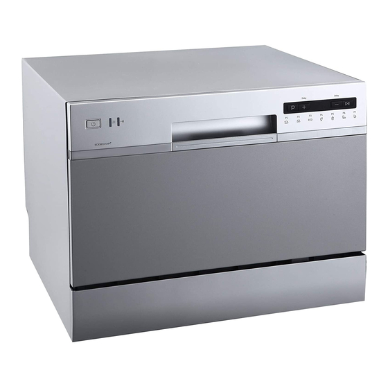
EdgeStar Countertop Dishwasher
MODEL(s):
DWP62BL
DWP62SV
DWP62WH
CAUTION: READ ALL SAFETY PRECAUTIONS IN
THIS MANUAL BEFORE SERVICING THE UNIT
EdgeStar, 8606 Wall St, Suite 1600, Austin, TX 78754
support.edgestar.com • service@edgestar.com • edgestar.com
*Warranty service should be performed by an authorized service representative only
.
Advertisement
Table of Contents

Related Manuals for EdgeStar DWP62BL


Summary of Contents for EdgeStar DWP62BL
- Page 1 DWP62BL DWP62SV DWP62WH CAUTION: READ ALL SAFETY PRECAUTIONS IN THIS MANUAL BEFORE SERVICING THE UNIT EdgeStar, 8606 Wall St, Suite 1600, Austin, TX 78754 support.edgestar.com • service@edgestar.com • edgestar.com *Warranty service should be performed by an authorized service representative only...
-
Page 2: Table Of Contents
CONTENTS CONTENTS ..............................1 SAFETY PRECAUTIONS ..........................1 ELECTRICAL SAFETY ..........................2 GENERAL SAFETY ..........................3 SPECIFICATIONS ............................4 EXPLODED VIEWS AND PARTS LISTS ..................... 5 WIRING DIAGRAM ............................. 10 CONTROL PANEL ............................11 DETERGENT AND RINSE AID ........................12 DISASSEMBLY AND PARTS REPLACEMENT .................. -
Page 3: Electrical Safety
Electrical Safety Do not exceed the power outlet ratings. It is recommended that the unit be connected to its own circuit. A standard electrical supply (120V, 60Hz), that is properly grounded in accordance with the National Electrical Code and all state and local codes and ordinances is required. ... -
Page 4: General Safety
General Safety Always unplug an appliance from the power supply before attempting any service. Disconnect the power cord by grasping the plug, not the cord. Do not allow children or pets to play on or in the appliance. ... -
Page 5: Specifications
Specifications Description of product Dishwasher (Portable / Countertop) Model DWP62BL / DWP62WH / DWP62SV Color Black / White / Silver Number of Place Settings Maximum Diameter of place Settings 10.5" Wash Cycles Quick Connect Adapter Faucet Adapter Accessories Drain Hose... -
Page 6: Exploded Views And Parts Lists
Exploded Views and Parts Lists **NOTE: Not all parts are stocked or considered serviceable / replaceable by manufacturer Description Description Handle Cover 106c Delay Decrease Button Control Panel Cover 106d Start Button Power Button Outer Door Light Cover Baseboard Button Cover Power and Display PCB 106a Program Button... - Page 7 Description Description Upper Door Gasket 205-c Friction Strip Door Latch 205-d Spring Inner Door Hinge Assembly(Right) Lower Door Gasket Soap Dispenser Hinge Assembly(Left) Dispenser Bracket 205-a Guide Vane Hinge Join Panel 205-b Friction Bar Hanger...
- Page 8 Description Description Upper Back Cover Air Breaker Assembly Outer Shell Door Caps Air Breaker Washer Upper Corner Cover Plate Air Breaker Nut Door Switch...
- Page 9 Description Description Base Plate Outlet Hose Clamp Left Base Plate Bracket Outlet Hose Door Spring Bracket Lower Flat Filter Friction Strip Guide Spray Arm Check Valve Right Base Plate Bracket Float Microswitch Connector Bracket Float Switch Holder Crimp Connector Float Main PCB box Upper Cylinder Filter Base Tray Cover...
- Page 10 Description Description Inlet Valve Wash Pump Motor Case Hose Clamp Wash Pump Motor Sealing Gasket Air Intake Inlet Hose Wash Pump Motor Sealing Ring Power Cord Wash Pump Motor Impeller Power Cord Clasp Impeller Screw Drain Pump Dish Rack Assembly Drain Hose Water Connection Components Hose Clamp...
-
Page 11: Wiring Diagram
Wiring Diagram... -
Page 12: Control Panel
Control Panel Power Button: Press to turn the dishwasher ON/OFF. Rinse Aid Warning Light: Indicates when the rinse aid dispenser needs to be refilled. Wash Cycle Complete Light: Indicates when the current wash cycle has ended. Program Selector: Press to select your wash cycle. The wash cycles will display in sequence. Delay Button Increase: Press to increase the time of the delay by one (1) hour increments up to 24 hours. -
Page 13: Detergent And Rinse Aid
Detergent and Rinse Aid USE PROPER DETERGENT ONLY Use only detergent specifically made for use in dishwashers. Keep your detergent fresh and dry. Do not put powder detergent into the dispenser until you are ready to wash dishes. The amount of detergent to use depends on whether your water is hard or soft. With hard water, you need extra detergent to alleviate the deposits that are left by the excessive minerals. -
Page 14: Disassembly And Parts Replacement
Disassembly And Parts Replacement Basic Precautions Always turn off the electric power supply before servicing or replacing any electrical component. If grounding wires, screws, straps, clips, nuts, or washers used to complete a path to ground are removed for service, they must be returned to their original position and properly fastened. ... - Page 15 Use a flat head screwdriver to release the nine (9) latches that secure the panel to the unit. While gripping the panel, lift upward as the latches are detached to more easily remove the panel. When latches are all released, remove the Base Tray Cover gently and be careful not to pull the overflow switch wiring.
- Page 16 Step 2: Remove the Drain Pump Locate the drain pump circled in the below image. Detach the electrical connectors from the pump.
- Page 17 Press the grey snap latch FIRST and then turn the drain pump counter clockwise to remove. Slide the pump out of the housing. Step 3: Install the new drain pump Slide the pump into the housing. Turn the pump clockwise until the locking latch clicks and the pump is locked in place.
- Page 18 Step 4: Reinstall the Base Tray Cover Locate the float switch on the Base Tray Cover and reattach the electrical connector. Push the Base Tray Cover into place securely latching the nine (9) snap latches. Reinstall the screw to secure the Base Tray Cover into place.
-
Page 19: Power Cord Removal And Replacement Instructions
Power Cord Removal and Replacement Instructions The air breaker functions to supply water for wash and rinse while preventing siphoning or back-flow of wash water into the water supply. It also functions to supply air venting to aid in dish drying. Tools and Parts Needed: - Phillips Screwdriver - Flat Tip Screwdriver... -
Page 20: Air Breaker Removal And Replacement Instructions
Air Breaker Removal and Replacement Instructions The air breaker functions to supply water for wash and rinse while preventing siphoning or back-flow of wash water into the water supply. It also functions to supply air venting to aid in dish drying. Tools and Parts Needed: - Phillips Screwdriver - Flat Tip Screwdriver... - Page 21 Step 3: Remove Clamps From the bottom of the unit, locate the four hoses that go to the air breaker as indicated with the arrows in the below image. Use a flat tip screwdriver to pry the clips securing the ends of the clamp together. ...
- Page 22 Step 5: Remove Air Breaker Nut Locate the Air Breaker Nut located on the interior wall of the unit. Remove the Air Breaker Nut by turning counter-clockwise. Step 6: Remove / Replace Air Breaker Assembly Remove the Air Breaker Assembly by pulling the air breaker outward away from the dishwasher cabinet ...
- Page 23 Step 7: Screw the Air Breaker Nut back into place Screw the Air Breaker Nut back into place by turning the nut clockwise. This nut should be firmly tightened by hand. Step 8: Reconnect electrical connection Reattach the electrical connector back to the Air Breaker Assembly Step 9: Attach the gear drive hose clamps ...
- Page 24 Step 10: Reattach the Outer Shell Reattach the outer shell and the base tray cover Line up the latches of the outer shell and the upper back cover to reinstall Reinstall the 8 screws attaching the outer shell to the rest of the unit Step 11: Reinstall the Base Tray Cover ...
-
Page 25: Baseboard Removal And Replacement
Baseboard Removal and Replacement The baseboard is decorative cover plate located on the lower front of the unit, underneath the door. If damaged, the baseboard is easily replaceable. Tools Needed: - Phillips Screwdriver - Flat Tip Screwdriver Step 1: Remove the Baseboard ... - Page 26 Step 2: Install the new Baseboard Line the 4 guides up into the slots making sure the wiring harness fits between the two guides in the center Slide the baseboard into the slots and slide the baseboard down into the snap latches. ...
-
Page 27: Check Valve Removal And Replacement
Check Valve Removal and Replacement The check valve is a one way valve that prevents wastewater in the drain system from flowing back into the pump. Tools and Parts Needed: - Phillips Screwdriver - Flat Tip Screwdriver - Needle nose pliers - Gear drive hose clamp (1) Step 1: Remove Base Tray Cover ... - Page 28 Remove the end of the hose from the drain pump. Step 3: Remove and replace the check valve Use needle nose pliers and gently pull the valve assembly out of the hose...
- Page 29 Slide the new check valve assembly into place NOTE: The drain pump is keyed so the valve can only go in one way. It is easiest to start pushing it in and slowly spin it until it slides over the keyway. ...
- Page 30 Circuit Board Removal and Replacement There are three (3) circuit boards found within the dishwasher. Two of these boards are for display and control panel functions and are referred to as ‘Control Circuit Boards’ or ‘Display Circuit Boards’. Additionally, there is a ‘Power Circuit Board’ that manages the power distribution within the unit. Note: OEM Replacement board kits will include all 3 boards.
- Page 31 Remove the electrical connection from the unit to the circuit board. Do not disconnect the connectors for the harness that goes between the two boards. Remove the four screws holding the boards to the door Remove the control circuit boards and install the new boards in the same configuration ...
- Page 32 Power Circuit Board: Step 1: Remove Base Tray Cover Refer to instructions to remove panel found in the “Drain Pump Removal and Replacement” section of this document Step 2: Remove and Replace Power Circuit Board Note: Make sure to take a picture of the wiring connections before unplugging them ...
- Page 33 Detach the electrical connectors from the circuit board Remove the circuit board and secure the new board into place in the same configuration Reattach the electrical connectors. Step 3: Reinstall the Base Tray Cover Refer to instructions to reinstall Base Tray Cover found in the “Drain Pump Removal and Replacement”...
-
Page 34: Float Assembly, Float Micro Switch And Float Removal And Replacement Instructions
Float Assembly, Float Micro Switch and Float Removal and Replacement Instructions Tools Needed: - Phillips Screwdriver - Flat Tip Screwdriver - Needle nose pliers Step 1: Remove Base Tray Cover Refer to instructions to remove panel found in the “Drain Pump Removal and Replacement” section of this document Step 2: Remove the float assembly cover ... - Page 35 Step 4: Reinstall the float assembly cover Slide the float assembly cover over the cylindrical latches making sure the micro switch is in the same orientation as it was prior to removal Step 5: Reinstall the Base Tray Cover ...
-
Page 36: Heating Element Removal And Replacement
Heating Element Removal and Replacement The heating element heats water as needed during wash and rinse cycle. Tools Needed: - Phillips Screwdriver - Flat Tip Screwdriver - Needle nose pliers - 8mm socket wrench Step 1: Remove Base Tray Cover ... - Page 37 Step 3: Disconnect the electrical connections for the heating element Take a picture of the 3 electrical connectors Using a flathead screwdriver, gently slide the 3 electrical connectors off of the heating element Step 4: Separate the Heating Element assembly from the Wash Motor ...
- Page 38 Step 5: Remove and replace the Heating Element Use an 8mm socket to remove the nut on the heating element Slide the heating element out of the housing NOTE: The replacement heating element will come with a new housing. If you have not damaged the original housing, it is easier to remove and replace just the element.
- Page 39 Step 7: Reconnect the Heating Element Assembly to the Wash Motor Ensure the O-ring gasket is in place Push the heating element housing against the wash motor and turn the housing clockwise until the snap latches lock into place.
- Page 40 Step 8: Reinstall the Wash Pump Assembly Seat the wash motor back into place. Using a flathead screwdriver, slide both of the rubber hold-downs over the latch assembly. NOTE: Be careful not to tear the rubber. Step 9: Reinstall the Base Tray Cover ...
-
Page 41: Inlet Valve Removal And Replacement
Inlet Valve Removal and Replacement The inlet valve controls the inflow of water into the dishwasher. The valve opens and closes to allow water into the unit based on signals from the control board. Tools Needed: - Phillips Screwdriver - Flat Tip Screwdriver - Needle nose pliers - Gear drive hose clamp (1) Step 1: Remove Base Tray Cover... - Page 42 Install the new inlet valve in the same orientation you removed it from Turn the valve to line up with the latches, and the snap latch will re-enage. Slide the gear drive clamp over the hose Slide the hose back over the inlet valve and tighten the clamp ...
-
Page 43: Door Component Replacement Removal And Replacement
Door Component Replacement Removal and Replacement Inner Door, Outer Door Panel, Control Panel Cover, and Soap Dispenser Tools Needed: - Phillips Screwdriver - Flat Tip Screwdriver - Needle nose pliers Step 1: Remove the Control Panel Cover Remove the 8 top Philips head screws on the inner door ... - Page 44 Step 2: Remove Outer Door Panel Remove the four lower Philips head screws from the inside of the door NOTE: Hold the outside panel so it does not fall when removing the final screws Slide the panel down off of the alignment pins and pull the panel away from the door...
- Page 45 Step 3: Remove the Soap Dispenser NOTE: This is a good time to take some pictures of the electrical connectors so you may refer back to them during reassembly Use needle nose pliers or a flat tip screwdriver to remove the electrical connectors from the soap dispenser NOTE: One of the locking electrical connectors may not be accessible with the dispenser installed.
- Page 46 Remove the soap dispenser by carefully pushing the part through the front of the door Step 4: Remove and replace the Inner Door Panel Remove the two Philips head screws on each side of the door With the door is in the almost closed position, lift up on the inner door detaching it from the frame of the unit ...
- Page 47 Step 5: Reinstall the soap dispenser Slide the soap dispenser into place in the same orientation you removed it from Tighten the six Philips head screws that secure the soap dispenser to the door NOTE: It is easiest to start the top three screws to hold the soap drawer then line up the lower bracket and install those screws.
- Page 48 Step 6: Reinstall the Outer Door Panel Line up the alignment pins with the holes on the door and slide the door up into place Start all four Philips head screws a few threads Once all four screws are started, tighten them with a Philips screwdriver...
- Page 49 Step 7: Reinstall the Control Panel Cover Reposition the door latch through the inner door Line the control panel cover up with the alignment pins Reattach the electrical connector to the control circuit boards Start the 8 Philips head screws a few threads each ...
-
Page 50: Door Gasket Removal And Replacement Instructions
Door Gasket Removal and Replacement Instructions The door gasket provides a water tight seal between the dishwasher door and cabinet. Inspect the door gasket periodically and replace when gasket appears excessively worn or damaged. Step 1: Remove Door Gasket Pinch the door gasket with your fingers and gently pull it away from the unit to remove. -
Page 51: Door Switch Removal And Replacement Instructions
Door Switch Removal and Replacement Instructions The door switch signals to the circuit board that the door is closed properly and the unit can begin a cycle. A failing switch may lead to an error code, failure to turn on, or it may even allow the unit to run without the door closed properly. - Page 52 Step 2: Remove and replace the door switch assembly Disconnect the two wires from the switch Release the snap latch for the switch Slide the switch assembly away from the snap latch Place the new switch assembly in place and slide towards the snap latch until it clicks ...
- Page 53 Step 3: Reattach the Outer Shell Reattach the outer shell and the base tray cover Line up the latches of the outer shell and the upper back cover to reinstall Reinstall the 8 screws attaching the outer shell to the rest of the unit...
-
Page 54: Troubleshooting
Troubleshooting SYMPTOM CHECK FOR THE FOLLOWING REMEDY The water supply is turned off Turn the water supply on Defective water inlet valve Replace the inlet valve E1 Error Code Low water pressure Minimum water pressure of 20 PSI Disassemble and clean the water inlet valve Obstructed water inlet valve or hose Dishwasher will not and hose... - Page 55 SYMPTOM CHECK FOR THE FOLLOWING REMEDY Obstructed drain hose Clean out drain hose This is necessary to keep the pump primed Water remains in A small amount of water (in sump area) is normal and is drained automatically at the beginning bottom of each cycle Defective drain pump...
- Page 56 DATE REVISION NOTES 03/22/2018 INITIAL DOCUMENT EdgeStar, 8606 Wall St, Suite 1600, Austin, TX 78754 support.edgestar.com • service@edgestar.com • edgestar.com *Warranty service should be performed by an authorized service representative only.