SMC Networks SMC TigerStack III SMC6826MPE Installation Manual
Tigerstack iii 10/100 24-port fast ethernet switch
Hide thumbs
Also See for SMC TigerStack III SMC6826MPE:
- Management manual (608 pages) ,
- Technical specifications (2 pages)
Table of Contents
Advertisement
Quick Links
TigerStack III 10/100
24-Port Fast Ethernet Switch
◆ 24 auto-MDI/MDI-X 10BASE-T/100BASE-TX ports
◆ 10BASE-T/100BASE-TX ports support PoE capabilities
◆ 2 Gigabit combo ports (RJ-45/SFP)
◆ 8.8 Gbps of aggregate bandwidth
◆ Stacks up to 8 units
◆ Non-blocking switching architecture
◆ Spanning Tree Protocol, RSTP, and MSTP
◆ Up to six LACP or static 4-port trunks
◆ RADIUS and TACACS+ authentication
◆ Rate limiting for bandwidth management
◆ CoS support for four-level priority
◆ Full support for VLANs with GVRP
◆ IP Multicasting with IGMP Snooping
◆ Manageable via console, Web, SNMP/RMON
Installation Guide
SMC6826MPE
Advertisement
Table of Contents
Troubleshooting

Related Manuals for SMC Networks SMC TigerStack III SMC6826MPE


Summary of Contents for SMC Networks SMC TigerStack III SMC6826MPE
-
Page 1: Installation Guide
TigerStack III 10/100 24-Port Fast Ethernet Switch ◆ 24 auto-MDI/MDI-X 10BASE-T/100BASE-TX ports ◆ 10BASE-T/100BASE-TX ports support PoE capabilities ◆ 2 Gigabit combo ports (RJ-45/SFP) ◆ 8.8 Gbps of aggregate bandwidth ◆ Stacks up to 8 units ◆ Non-blocking switching architecture ◆... - Page 3 TigerStack III 10/100 Installation Guide From SMC’s Tiger line of feature-rich workgroup LAN solutions 38 Tesla Irvine, CA 92618 Phone: (949) 679-8000 June 2005 Pub. # 150200037700A...
- Page 4 38 Tesla Irvine, CA 92618 All rights reserved. Trademarks: SMC is a registered trademark; and EZ Switch, TigerStack and TigerSwitch are trademarks of SMC Networks, Inc. Other product and company names are trademarks or registered trademarks of their respective holders.
- Page 5 IMITED ARRANTY Limited Warranty Statement: SMC Networks, Inc. (“SMC”) warrants its products to be free from defects in workmanship and materials, under normal use and service, for the applicable warranty term. All SMC products carry a standard 90-day limited warranty from the date of purchase from SMC or its Authorized Reseller.
- Page 6 * SMC will provide warranty service for one year following discontinuance from the active SMC price list. Under the limited lifetime warranty, internal and external power supplies, fans, and cables are covered by a standard one-year warranty from date of purchase. SMC Networks, Inc. 38 Tesla Irvine, CA 92618...
-
Page 7: Japan Vcci Class A
Warnings: 1. Wear an anti-static wrist strap or take other suitable measures to prevent electro- static discharge when handling this equipment. 2. When connecting this switch to a power outlet, connect the field ground lead on the tri-pole power plug to a valid earth ground line to prevent electrical hazards. - Page 8 OMPLIANCES CE Mark Declaration of Conformance for EMI and Safety (EEC) This information technology equipment complies with the requirements of the Council Directive 89/336/EEC on the Approximation of the laws of the Member States relating to Electromagnetic Compatibility and 73/23/EEC for electrical equipment used within certain voltage limits and the Amendment Directive 93/68/EEC.
- Page 9 Faserkabelenden schauen, während diese eingeschaltet sind. Power Cord Safety Please read the following safety information carefully before installing the switch: Warning: Installation and removal of the unit must be carried out by qualified personnel only. • The unit must be connected to an earthed (grounded) outlet to comply with international safety standards.
- Page 10 HO3VVF3GO.75 (minimum). IEC-320 receptacle. Veuillez lire à fond l'information de la sécurité suivante avant d'installer le Switch: AVERTISSEMENT: L’installation et la dépose de ce groupe doivent être confiés à un personnel qualifié. • Ne branchez pas votre appareil sur une prise secteur (alimentation électrique) lorsqu'il n'y a pas de connexion de mise à...
- Page 11 • Le coupleur d’appareil (le connecteur du groupe et non pas la prise murale) doit respecter une configuration qui permet un branchement sur une entrée d’appareil EN 60320/IEC 320. • La prise secteur doit se trouver à proximité de l’appareil et son accès doit être facile. Vous ne pouvez mettre l’appareil hors circuit qu’en débranchant son cordon électrique au niveau de cette prise.
-
Page 12: Warnings And Cautionary Messages
Warning: This switch uses lasers to transmit signals over fiber optic cable. The lasers are compliant with the requirements of a Class 1 Laser Product and are inherently eye safe in normal operation. -
Page 13: End Of Product Life Span
All printed documentation for this product uses biodegradable paper that originates from sustained and managed forests. The inks used in the printing process are non-toxic. Purpose This guide details the hardware features of the switch, including Its physical and perfor- mance-related characteristics, and how to install the switch. OMPLIANCES... -
Page 14: Related Publications
The following publication gives specific information on how to operate and use the manage- ment functions of the switch: The 24-Port Fast Ethernet PoE Switch Management Guide Also, as part of the switch’s firmware, there is an online web-based help that describes all management related features. viii... -
Page 15: Table Of Contents
Switch Architecture ........1-2... - Page 16 ABLE OF ONTENTS Mounting ........... 3-4 Rack Mounting .
- Page 17 Troubleshooting ....... A-1 Diagnosing Switch Indicators ........A-1 Diagnosing Power Problems with the LED Indicators .
- Page 18 ABLES Table 1-1 Port Status LED Indicators ......1-5 Table 1-2 System Status LED Indicators ......1-7 Table 3-1 Serial Cable Wiring .
- Page 19 Attaching the Brackets ......3-5 Figure 3-3 Installing the Switch in a Rack ..... 3-5 Figure 3-4 Attaching the Adhesive Feet .
- Page 20 IGURES...
-
Page 21: About The Tigerstack Iii 10/100
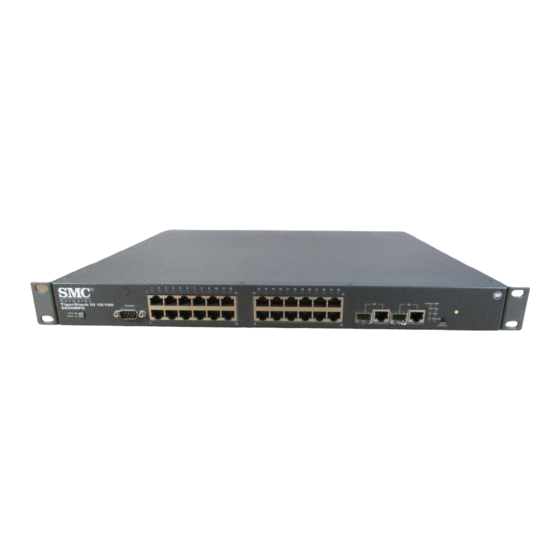
TACK Overview SMC’s TigerStack III 10/100 SMC6826MPE is a 24-Port Fast Ethernet PoE Switch with 24 10BASE-T/100BASE-TX RJ-45 ports and two combination ports — 10/100/1000BASE-T ports that operate in combination with Small Form Factor Pluggable (SFP) transceiver slots An optional SFP stacking transceiver is available for connecting up to eight units to a 2 Gbps stack backplane. -
Page 22: Switch Architecture
SFP slots. The optional SFP stacking transceiver enables up to eight units to be connected together through a 1 Gbps stack backplane. The switch stack can be managed from a master unit using a single IP address. -
Page 23: Network Management Options
VERVIEW from the switch over the Ethernet cable without requiring its own separate power source. This capability gives network administrators centralized power control for devices such as IP phones and wireless access points, which translates into greater network availability. For each attached 802.3af-compliant device, the switch automatically senses the load and dynamically supplies the required power. -
Page 24: Description Of Hardware
TACK Description of Hardware 10/100BASE-T Ports The PoE switch base unit contains 24 10BASE-T/100BASE-TX RJ-45 ports. All ports support automatic MDI/MDI-X operation, so you can use straight-through cables for all network connections to PCs or servers, or to other switches or hubs. (See “10/100BASE-TX Pin Assignments” on page B-2.) -
Page 25: Port And System Status Led Indicators
Port and System Status LED Indicators The switch base unit also includes a display panel for key system and port indications that simplify installation and network troubleshooting. The LED indicators, which are located on the front panel for easy viewing, are shown below and described in the following tables. - Page 26 Powered device is receiving power. Port has detected a power overload or short circuit and shut down the port’s power. The power budget for the switch has been exceeded and the port's power shut down. Port power has been turned off by the administrator.
-
Page 27: Table 1-2 System Status Led Indicators
Table 1-2 System Status LED Indicators Condition On Green Diag On Green Flashing Green On Amber Flashing Amber Alternate Green/ Amber On Green On Amber System Status LEDs Link/Act Diag Stacking Figure 1-3 System LED Indicators Status Unit’s internal power supply is operating normally. -
Page 28: Stack Master Button
Stack Master Button The unit also includes a Stack Master button shown in the following diagram. Stack Master Button The Stack Master button enables one switch in the stack to be selected as the master. III 10/100 Status This switch is acting as the master unit in the stack. -
Page 29: Mode Poe/Link Button
Mode PoE/Link Button The Mode PoE/Link button is located on the front panel. The Mode PoE/Link button is used to toggle between the two port status LED display modes (see “Port Status LED Indicators” on page 1-5). Pressing this button changes from one display mode to the other. The default display mode is Link/Act mode. -
Page 30: Power Supply Sockets
(one stacking cable is included with each optional stacking transceiver). The push button on the switch’s front panel enables one switch in the stack to be selected as the master. (See “Stack Master Button” on page 1-8.) Power Supply Sockets There are two power sockets on the rear panel of the switch. -
Page 31: Expandability
• Unshielded (UTP) cable supported on all RJ-45 ports: Category 3 or better for 10 Mbps connections, Category 5 or better for 100 Mbps connections, and Category 5, 5e or 6 for 1000 Mbps connections • IEEE 802.3-2002 Ethernet, Fast Ethernet, Gigabit Ethernet, and flow control compliance ensures compatibility with standards-based hubs, network cards and switches from any vendor •... -
Page 32: Management
BOUT THE IGER TACK Management • “At-a-glance” LED indicators for easy troubleshooting • Network management agent: Manages switch (or entire stack) in-band or out-of-band Supports console, Telnet, SSH, SNMP v1/v2c/v3, 4 RMON groups and web-based interface 1-12 III 10/100... -
Page 33: Network Planning
When networks are based on repeater (hub) technology, the distance between end stations is limited by a maximum hop count. However, a switch turns the hop count back to zero. So subdividing the network into smaller and more manageable segments, and linking them to the larger network by means of a switch, removes this limitation. -
Page 34: Application Examples
PoE device to the network and build on this basic configuration, to allow power to be delivered over the connection to the PoE device. Each of the 24 ports on the switch can provide power to a connected device. -
Page 35: Collapsed Backbone
Fast Ethernet or Gigabit Ethernet ports. In the figure below, the switch is operating as a collapsed backbone for a small LAN. It is providing dedicated 10 Mbps full-duplex connections to workstations and 100 Mbps full-duplex connections to power users and servers. -
Page 36: Network Aggregation Plan
When up to eight switch units are stacked together, they form a single “virtual” switch containing up to 200 ports. The whole stack can be managed through the Master unit using a single IP address. -
Page 37: Remote Connections With Fiber Cable
550 m, a 1000BASE-LX single-mode fiber (SMF) link can run up to 5 km, and a 1000BASE-LH single-mode fiber (SMF) link can run up to 70 km. This allows the switch to serve as a collapsed backbone, providing direct connectivity for a widespread LAN. -
Page 38: Making Vlan Connections
ETWORK LANNING Making VLAN Connections This switch supports VLANs which can be used to organize any group of network nodes into separate broadcast domains. VLANs confine broadcast traffic to the originating group, and can eliminate broadcast storms in large networks. This provides a more secure and cleaner network environment. -
Page 39: Application Notes
1. Full-duplex operation only applies to point-to-point access (such as when a switch is attached to a workstation, server or another switch). When the switch is connected to a hub, both devices must operate in half-duplex mode. 2. Avoid using flow control on a port connected to a hub unless it is actually required to solve a problem. - Page 40 ETWORK LANNING...
-
Page 41: Installing The Switch
NSTALLING THE Selecting a Site Switch units can be mounted in a standard 19-inch equipment rack or on a flat surface. Be sure to follow the guidelines below when choosing a location. • The site should: - be at the center of all the devices you want to link and near a power outlet. -
Page 42: Ethernet Cabling
As with any equipment, using a filter or surge suppressor is recommended. Ethernet Cabling To ensure proper operation when installing the switch into a network, make sure that the current cables are suitable for 10BASE-T or 100BASE-TX operation. Check the following criteria against the current installation of your network: •... -
Page 43: Equipment Checklist
Equipment Checklist After unpacking this switch, check the contents to be that sure you have received all the components. Then, before beginning the installation, be sure that you have all other necessary installation equipment. Package Contents • 24-Port Fast Ethernet PoE Switch •... -
Page 44: Mounting
NSTALLING THE WITCH Mounting This switch can be mounted in a standard 19-inch equipment rack or on a desktop or shelf. Mounting instructions for each type of site follow. Rack Mounting Before rack mounting the switch, pay particular attention to the following factors: •... -
Page 45: Figure 3-2 Attaching The Brackets
Figure 3-3 Installing the Switch in a Rack 3. If installing a single switch only, turn to “Connecting to a Power Source” at the end of this chapter. 4. If installing multiple switches, mount them in the rack, one below the other, in any order. - Page 46 Schrauben an dem Gerät. Befestigen Sie das Gerät mit vier Rackmontageschrauben (nicht beigelegt) an dem Rack. Wenn Sie nur einen Switch installieren, dann springen Sie bitte über zu "Verbinden mit einer Stromquelle" auf Seite 3-12 am Ende dieses Kapitels. Wenn Sie mehrere Switches installieren möchten, dann montieren Sie sie untereinander...
-
Page 47: Desktop Or Shelf Mounting
2. Set the device on a flat surface near an AC power source, making sure there are at least two inches of space on all sides for proper air flow. 3. If installing a single switch only, go to “Connecting to a Power Source” at the end of this chapter. -
Page 48: Installing An Sfp Transceiver
3. Slide the SFP transceiver into the slot until it clicks into place. Note: SFP transceivers are hot-swappable. The switch does not need to be powered off before installing or removing a transceiver. -
Page 49: Stacking Switches
Stacking Switches The switch supports stacking up to eight units through an optional SFP stacking transceiver. Each stacking connection provides a 2 Gbps high-speed link using USB stacking cables. The stacking transceiver must be installed in the port 25 SFP slot. Each stacking transceiver has two connectors, Tx and Rx, for attaching stacking cables. -
Page 50: Connecting Switches In A Stack
To connect up to eight switches in a stack, perform the following steps: 1. Install SFP stacking transceivers into the port 25 slot for each switch in the stack. 2. Plug one end of a stack cable into the Tx (top) port of the top unit 3. - Page 51 6. Select the Master unit in the stack by pressing the push button in on only one of the switches. Only one switch in the stack can operate as the Master, all other units operate in slave mode. If more than one switch in the stack is selected as Master, or if no switches are selected, the stack will not function.
-
Page 52: Connecting To A Power Source
NSTALLING THE WITCH Connecting to a Power Source To connect a switch to a power source: 1. Insert the power cable plug directly into the AC socket located at the back of the switch. 2. Plug the other end of the cable into a grounded, 3-pin socket, AC power source. -
Page 53: Connecting To The Console Port
Connecting to the Console Port The DB-9 serial port on the switch’s front panel is used to connect to the switch for out-of-band console configuration. The command-line configuration program can be accessed from a terminal or a PC running a terminal emulation program. - Page 54 NSTALLING THE WITCH • Stop bit—One • Data bits—8 • Flow control—none 3-14...
-
Page 55: Making Network Connections
Connecting Network Devices The switch is designed to be connected to 10 or 100 Mbps network cards in PCs and servers, as well as to other switches and hubs. It may also be connected to remote devices using the optional 1000BASE-X, or 100BASE-FX SFP transceivers. -
Page 56: Power-Over-Ethernet Connections
The switch delivers power to a device using the two signal wire pairs in UTP or STP cable (RJ-45 pins 1, 2, 3, and 6). The switch can provide up to 15.4 W of power continuously on each 10/100 Mbps port. However, taking into account some power loss over the cable run, the amount of power that can be delivered to a terminal device is 12.95 W. -
Page 57: Cabling Guidelines
Cabling Guidelines The RJ-45 ports on the switch support automatic MDI/MDI-X pinout configuration, so you can use standard straight-through twisted-pair cables to connect to any other network device (PCs, servers, switches, routers, or hubs). See Appendix B for further information on cabling. -
Page 58: Network Wiring Connections
AKING ETWORK 3. If the device is a network card and the switch is in the wiring closet, attach the other end of the cable segment to a modular wall outlet that is connected to the wiring closet. (See the section “Network Wiring Connections”... -
Page 59: Figure 4-2 Network Wiring Connections
Switch Link/Act Console Diag Stack Mode PoE /Link Patch Panel Figure 4-2 Network Wiring Connections WISTED Equipment Rack (side view) Punch-Down Block Wall EVICES... -
Page 60: Fiber Optic Devices
50/125 or 62.5/125 micron multimode fiber optic cabling with an LC connector at both ends. Warning: This switch uses lasers to transmit signals over fiber optic cable. The lasers are compliant with the requirements of a Class 1 Laser Product and are inherently eye safe in normal operation. -
Page 61: Connectivity Rules
3. Connect one end of the cable to the LC port on the switch and the other end to the port on the other device. Since LC connectors are keyed, the cable can be attached in only one orientation. LC fiber... -
Page 62: 1000Base-T Cable Requirements
AKING ETWORK 1000BASE-T Cable Requirements All Category 5 UTP cables that are used for 100BASE-TX connections should also work for 1000BASE-T, providing that all four wire pairs are connected. However, it is recommended that for all critical connections, or any new cable installations, Category 5e (enhanced Category 5) or Category 6 cable should be used. -
Page 63: 100 Mbps Fast Ethernet Collision Domain
Table 4-4 Maximum 1000BASE-LH Gigabit Ethernet Cable Length Fiber Size 9/125 micron single-mode fiber 100 Mbps Fast Ethernet Collision Domain Table 4-5 Maximum Fast Ethernet Cable Lengths Type Cable Type 100BASE-TX Category 5 or better 100-ohm UTP or STP 100BASE-FX 50/125 or 62.5/125 micron core Multimode multimode fiber (MMF) - Page 64 • Note the length of each cable and the maximum cable length supported by the switch ports. • For ease of understanding, use a location-based key when assigning prefixes to your cable labeling.
-
Page 65: Troubleshooting
• Internal power supply may be disconnected. Check connections between the switch, the power cord and the wall outlet. • The system has detected a fault. Power cycle the switch to try and clear the condition. • If the condition does not clear, contact your dealer for assistance. -
Page 66: Diagnosing Power Problems With The Led Indicators
ROUBLESHOOTING Diagnosing Power Problems with the LED Indicators The Power and RPU LED indicators work in combination to indicate power status as follows. Table A-2 Power/RPU LED Indicators Power LED RPU LED Status Green Green Green Amber Green Amber Green Power and Cooling Problems If the power indicator does not turn on when the power cord is plugged in, you may have a problem with the power outlet, power cord, or internal... -
Page 67: Installation
Then verify that you entered the correct IP address. Also, be sure the port through which you are connecting to the switch has not been disabled. If it has not been disabled, then check the network cabling that runs between your remote location and the switch. -
Page 68: Stack Troubleshooting
ROUBLESHOOTING Stack Troubleshooting If a stack fails to initialize or function, first check the following items: • Check that all stacking cables are properly connected. • Check if any stacking cables appear damaged. • Check that only one Master Select button is pressed in. •... -
Page 69: Cables
Twisted-Pair Cable and Pin Assignments For 10/100BASE-TX connections, the twisted-pair cable must have two pairs of wires. For 1000BASE-T connections the twisted-pair cable must have four pairs of wires. Each wire pair is identified by two different colors. For example, one wire might be green and the other, green with white stripes. -
Page 70: Table B-1 10/100Base-Tx Mdi-X And Mdi Port Pinouts
100 meters (328 feet). Data and PoE power are delivered on the standard two wire pairs (pins 1, 2, 3, and 6). Since the RJ-45 ports on the switch base unit support automatic MDI/MDI-X operation, you can use straight-through cables for all network connections to PCs or servers, or to other switches or hubs. -
Page 71: Twisted-Pair Cable And Pin Assignments
(MDI-X), the two pairs of wires must be straight-through. (When auto-negotiation is enabled for any RJ-45 port on this switch, you can use either straight-through or crossover cable to connect to any device type.) You must connecting all four wire pairs as shown in the following diagram to support Gigabit Ethernet connections. -
Page 72: Crossover Wiring
“X” (MDI-X) or neither port is labeled with an “X” (MDI), a crossover must be implemented in the wiring. (When auto-negotiation is enabled for any RJ-45 port on this switch, you can use either straight-through or crossover cable to connect to any device type.) You must connect all four wire pairs as shown in the following diagram to support Gigabit Ethernet connections. -
Page 73: 1000Base-T Pin Assignments
WISTED ABLE AND SSIGNMENTS 1000BASE-T Pin Assignments All 1000BASE-T ports support automatic MDI/MDI-X operation, so you can use straight-through cables for all network connections to PCs or servers, or to other switches or hubs. The table below shows the 1000BASE-T MDI-X and MDI port pinouts. These ports require that all four pairs of wires be connected. -
Page 74: Table B-2 1000Base-T Mdi-X And Mdi Port Pinouts
ABLES Table B-2 1000BASE-T MDI-X and MDI Port Pinouts 1000BASE-T MDI-X and MDI Port Pinouts MDI-X Signal Name Bi-directional Data Two Plus (BI_D2+) Bi-directional Data Two Minus (BI_D2-) Bi-directional Data One Plus (BI_D1+) Bi-directional Data Four Plus (BI_D4+) Bi-directional Data Four Minus (BI_D4-) Bi-directional Data One Minus (BI_D1-) -
Page 75: Fiber Standards
IBER TANDARDS Adjusting Existing Category 5 Cabling to Run 1000BASE-T If your existing Category 5 installation does not meet one of the test parameters for 1000BASE-T, there are basically three measures that can be applied to try to correct the problem: 1. - Page 76 ABLES...
-
Page 77: Specifications
Physical Characteristics Ports 24 10/100BASE-TX, with auto-negotiation 2 1000BASE-T/SFP combination ports Network Interface Ports 1-24: RJ-45 connector, auto MDI/X 10BASE-T: RJ-45 (100-ohm, UTP cable; Categories 3 or better) 100BASE-TX: RJ-45 (100-ohm, UTP cable; Category 5 or better) Ports 25, 26: RJ-45 connector, auto MDI/X 1000BASE-T: RJ-45 (100-ohm, UTP cable;... -
Page 78: Switch Features
44.0 x 41.0 x 4.3 cm (17.32 x 16.14 x 1.69 in.) Temperature Operating: 0°C to 50°C (32°F to 122°F) Storage: -40°C to 70°C (-40°F to 158°F) Humidity Operating: 5% to 95% (non-condensing) Switch Features Forwarding Mode Store-and-forward Throughput Wire speed Flow Control Full Duplex: IEEE 802.3x... -
Page 79: Management Features
Management Features In-Band Management Web, Telnet, SSH, or SNMP manager Out-of-Band Management RS-232 DB-9 console port Software Loading TFTP in-band, or XModem out-of-band Standards IEEE 802.3-2002 Ethernet, Fast Ethernet, Gigabit Ethernet, Full-duplex flow control IEEE 802.3af Power-over-Ethernet IEEE 802.3p priority tags IEEE 802.3ac VLAN tagging IEEE 802.1D Spanning Tree Protocol IEEE 802.1w Rapid Spanning Tree Protocol... -
Page 80: Compliances
PECIFICATIONS Compliances CE Mark Emissions Industry Canada Class A EN55022 (CISPR 22) Class A FCC Class A Industry Canada Class A EN55022 (CISPR 22) Class A EN 61000-3-2/3 VCCI Class A C-Tick - AS/NZS 3548 (1995) Class A Immunity EN 61000-4-2/3/4/5/6/8/11 Safety CSA/CUS (CSA60950-1 &... -
Page 81: Table D-1 Tigerstack Iii 10/100 Products And Accessories
RDERING Table D-1 TigerStack III 10/100 Products and Accessories Product Number Description SMC6826MPE 24-port 10/100 stackable PoE switch with 2 Gigabit combination 1000BASE-T/SFP ports SMC6824S-P TigerStack III 10/100 Stacking Kit (includes 1 m stacking cable) SMCBGSLCX1 1-port 1000BASE-SX Small Form Pluggable (SFP) -
Page 82: Ordering Information
RDERING NFORMATION... -
Page 83: Glossary
10BASE-T IEEE 802.3 specification for 10 Mbps Ethernet over two pairs of Category 3, 4, or 5 UTP cable. 100BASE-FX IEEE 802.3u specification for Fast Ethernet over two strands of 50/125, 62.5/125 or 9/125 micron core fiber cable. 100BASE-TX IEEE 802.3u specification for 100 Mbps Ethernet over two pairs of Category 5 UTP cable. - Page 84 LOSSARY Auto-Negotiation Signalling method allowing each node to select its optimum operational mode (e.g., speed and duplex mode) based on the capabilities of the node to which it is connected. Bandwidth The difference between the highest and lowest frequencies available for network signals.
- Page 85 Fast Ethernet A 100 Mbps network communication system based on Ethernet and the CSMA/CD access method. Gigabit Ethernet A 1000 Mbps network communication system based on Ethernet and the CSMA/CD access method. Full Duplex Transmission method that allows two network devices to transmit and receive concurrently, effectively doubling the bandwidth of that link.
- Page 86 LOSSARY IEEE 802.3x Defines Ethernet frame start/stop requests and timers used for flow control on full-duplex links. (Now incorporated in IEEE 802.3-2002.) IEEE 802.3z Defines CSMA/CD access method and physical layer specifications for 1000BASE Gigabit Ethernet over fiber cabling. (Now incorporated in IEEE 802.3-2002.) LAN Segment Separate LAN or collision domain.
- Page 87 Network Diameter Wire distance between two end stations in the same collision domain. Redundant Power Supply (RPS) A backup power supply unit that automatically takes over in case the primary power supply should fail. RJ-45 Connector A connector for twisted-pair wiring. Switched Ports Ports that are on separate collision domains or LAN segments.
- Page 88 LOSSARY Glossary-6...
-
Page 89: Index
Fast Ethernet connectivity rules 4-6 features C-2 management 1-8 switch 1-7 fiber cables 4-4 flow control, IEEE 802.3x 1-3 front panel of switch 1-1 full duplex connectivity 2-1 Gigabit Ethernet cable lengths 4-5 grounding for racks 3-3 hot-swap, SFP 3-7 Index-1... - Page 90 NDEX IEEE 802.3x flow control 1-3 indicators, LED 1-3 installation connecting devices to the switch 4-2 network wiring connections 4-3 port connections 4-1 power requirements 3-1 problems A-2 rack mounting 3-3 SFP transceivers 3-7 site requirements 3-1 laser safety 4-4...
- Page 91 C-2 IEEE C-3 status LEDs 1-3 surge suppressor, using 3-1 switch architecture 1-2 switching introduction to 2-1 method 1-2 Telnet A-3 temperature within a rack 3-3 troubleshooting in-band access A-3 power and cooling problems A-2 switch indicators A-1...
- Page 92 NDEX Index-4...
- Page 94 FOR TECHNICAL SUPPORT, CALL: From U.S.A. and Canada (24 hours a day, 7 days a week) (800) SMC-4-YOU; (949) 679-8000; Fax: (949) 679-1481 From Europe (8:00 AM - 5:30 PM UK Time) 44 (0) 118 974 8700; Fax: 44 (0) 118 974 8701 INTERNET E-mail addresses: techsupport@smc.com...